1
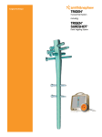
Surgical Technique
Table of contents
Introduction...................................................................................2
TRIGEN™ META-NAIL™ Retrograde Femoral Nail Specifications......3
Surgical technique.........................................................................4
Establish the incision and entry point.................................................5
Entry portal acquisition........................................................................6
Entry portal........................................................................................... 7
Alternative technique: Entry portal...................................................... 7
Reduce the fracture..............................................................................8
Determine the implant length..............................................................9
Reamed technique..............................................................................10
Nail assembly...................................................................................... 11
Nail insertion.......................................................................................12
Check nail depth.................................................................................12
Lock the screw....................................................................................13
Distal locking.......................................................................................14
Proximal locking..................................................................................15
TRIGEN Nail Cap and Nail Cap Set screw insertion: optional............16
Nail extraction: optional...................................................................... 17
An alternative method for extraction..................................................18
Catalog information..................................................................... 19
Appendix A................................................................................. 23
Blocking screw technique..................................................................23
Establish the entry portal...................................................................23
AP blocking screw insertion..............................................................23
ML blocking screw insertion..............................................................24
Blocking screw insertion with a reducer...........................................25
Final view: AP and ML blocking screw insertion...............................25
Stability blocking screw insertion......................................................25
Final view: Stability blocking screws..................................................26
Appendix B...................................................................................27
TRIGEN STABLE-LOK™ Nut and Washer.............................................. 27
Nota Bene
The technique description herein is made available to the healthcare professional
to illustrate the authors’ suggested treatment for the uncomplicated procedure.
In the final analysis, the preferred treatment is that which addresses the needs of
the patient.
1
Introduction
The following technique is for informational and
educational purposes only. It is not intended to
serve as medical advice. It is the responsibility
of treating physicians to determine and utilize
the appropriate products and techniques,
according to their own clinical judgment, for
each of their patients. For more information on
the TRIGEN™ META-NAIL™ Retrograde Femoral
Nail System, including its indications for
use, contraindications, and product safety
information, please refer to the product’s
label, the Instructions for Use (REF 81068703)
packaged with the product, and, if using the
TRIGEN SURESHOT™ Distal Targeting System, the
TRIGEN SURESHOT Distal Targeting System User
Manual (REF 7118-1540).
The TRIGEN META-NAIL Retrograde Femoral
Nail is indicated for fractures of the femur
including stable and unstable distal
metaphyseal fractures, diaphyseal fractures,
intraarticular fractures, periprosthetic fractures,
nonunions, malunions and for the prophylactic
nailing of impending pathological fractures.
The META-NAIL System can be used with
or without the SURESHOT Distal Targeting
System. If using the SURESHOT Distal
Targeting System, be sure to read and
understand the TRIGEN SURESHOT Distal
Targeting System User Manual (REF 7118-1540).
Only trained operators are allowed to use the
TRIGEN SURESHOT Distal Targeting System.
2
TRIGEN™ META-NAIL™ Retrograde Femoral
Nail Specifications
15mm
Specifications
TRIGEN META-NAIL Retrograde Femoral
Material
TI6Al4V
Diameter
10, 11.5 and 13mm
Lengths
18–50cm*
Nail color
Gold
Cross section
Round
Distal diameter
(driving end)
12mm (10, 11.5 diameter)
13mm (13 diameter)
Proximal diameter
(non-driving end)
10, 11.5 and 13mm
35mm
Non-driving end of nail
Smallest through diameter 5.0mm
25º
R 2M
25º
Top view of nail
100mm
Wall thickness
2.3mm (10 diameter)
3.0mm (11.5 diameter)
2.3mm (13 diameter)
Guide bolt thread
5/16–24 UNF
Screw diameter
5.0mm
Screw color
Gold
Major diameter
5.0mm
Minor diameter (core)
4.3mm
Screw lengths
25–110mm
Hex size
4.7mm
Alternative hexdrivers
RT Femoral and Recon
7.0mm Cannulated Screw
PERI-LOC™ 4.7mm Hexdriver, PROFIX™ 4.7mm Hexdriver
Alternative modes
No
Distal Locking (driving end)
30mm
40mm
15mm
Driving end of nail
ML view
Note: These views are not to scale and should
be used as a pictorial representation only.
Static lock
locations/orientations
15mm/ML – Threaded, can be locked with
META-NAIL cap set screw
30mm/25° – Threaded w/bushing
40mm/25° – Threaded w/bushing
Static locking hole
dimensions
Threaded 4.5mm minor diameter
Threaded 5.3mm major diameter
Proximal Locking
(non-driving end)
Static lock locations/
orientations
15mm/AP
35mm/AP
Static locking hole
dimensions
5.3mm
Proximal screw hole
diameter
5.3mm
AP bow radius
2m
AP bow location
Starts 100mm from driving end
* Set does not include all sizes; Additional sizes may be special order only.
3
Surgical technique
Patient positioning
1. Position
the patient supine on a radiolucent
table. Flex the affected limb approximately
45° over a posterior support to assist with
fracture reduction (Figure 1). Check for
length and rotation by comparison to the
unaffected limb.
2.Rotate
the C-Arm to ensure optimal AP
(anteroposterior) and lateral visualization of
the entire femur. The C-Arm should be able
to freely access the femur up to and including
the intertrochanteric area. A distraction
device may also be applied to obtain and/or
maintain traction.
Figure 1
3.Address
intra-articular fracture components
with interfragmentary screw fixation prior to
nail insertion. Be sure to place the screws in
the anterior and posterior aspect of the
distal femur and safely out of the nail’s
intended path.
Note: Cannulated screw Guide Pins allow
confirmation of definitive screw placement
prior to fracture fixation and nail insertion.
4.Use
a bolster or radiolucent triangle to
maintain limb position. Rotate the C-Arm to
ensure optimal AP and lateral visualization
of the entire femur. A distraction device may
also be applied to obtain and/or maintain
traction (Figure 2).
Caution: If using the TRIGEN™ SURESHOT™
Distal Targeting System, verify that there are
no metal objects in the immediate targeting
area. Metal interference will cause the
SURESHOT System to be inaccurate.
4
Figure 2
Establish the incision and
entry portal
1. Inspect
the Entry Portal Tube (7167-4060)
to ensure that it is not damaged, bent or
chipped. Any flaws in the tube can lead
to damage of the surrounding tendons
and tissues.
the Honeycomb (7167-4075), Entry
Portal Handle (7167-4092), and Entry Tube
(Figure 3) by pulling back the black trigger of
the Entry Portal Handle and inserting the Entry
Tube into the handle ring.
Entry Portal Tube
Honeycomb
2.Assemble
Entry Portal Handle
Figure 3
Turn the tube until it clicks into the
locked position.
Optional: Suction can be applied to the Entry
Portal Handle.
3.Make
a 3–4cm midline skin incision, followed
by a medial parapatellar capsular incision
to expose the intercondylar notch (Figure 4).
Gently retract the patellar
tendon laterally.
Figure 4
5
Entry portal acquisition
Locate the entry point within the intercondylar
notch just anterior and lateral to the femoral
attachment of the posterior cruciate ligament
(Figure 5).
1. Attach
a 3.2mm Brad Point Guide Pin
(7167-4130 or 7163-1436) to the drill via the
Mini Connector (7163-1186).
Figure 5
2.Insert
the Guide Pin into the distal femoral
metaphysis to a depth of 6–8cm (Figure 6).
Note: The entry portal instrumentation serves
as a soft-tissue protector.
3.The
Guide Pin should be in line with the
femoral axis in the AP view and anterior to
Blumensaat’s Line in the lateral view (Figure 7).
Note: If suboptimal Guide Pin insertion
occurs, rotate the Honeycomb within the
Entry Portal Tube to the desired location and
insert another 3.2mm Brad Point Guide Pin
(Figure 8).
Figure 6
Note: Do not over-insert the Guide Pin as
this can establish a false trajectory and cause
fracture malalignment.
Blumensaat’s Line
Figure 7
Figure 8
6
Entry portal
1. After
Guide Pin placement, remove the
Honeycomb (7167-4075) from the Entry Tube
along with any additionally inserted
Guide Pins.
2.Attach
the 12.5mm Entry Reamer (7163-1116)
to a power drill. Advance the reamer over the
Guide Pin and through the Entry Tube to a
depth of 6–8cm (Figure 8).
3.Check
the position of the Entry Reamer via
radiographic imaging and then remove the
Entry Reamer and Guide Pin.
Figure 9
Alternative technique:
Entry portal
1. With
the Entry Tube and Entry Portal Handle
still in the joint space, attach the T-handle
(7167-4076 or 7167-4576) to the Cannulated
Awl (Figure 9).
Figure 10
Note: Introduce the 3.2mm T-handle Trocar
(7167-4074) (Figure 10) into the back of the
assembly prior to insertion in order to prevent
awl slippage and the accumulation of cortical
bone within the cannulation.
Figure 11
2.Insert
the awl into the distal femur to a depth
of 6–8cm.
7
Reduce the fracture
1.
Open the Gripper (7167-4080).
2.
Insert the smooth end of the 3.0mm Ball Tip
Guide Rod (7163-1626) into the front of the
Gripper (Figure 12) and gently close the
trigger grip.
3.
4.
Connect the 8.5mm Reducer and the Reducer
Connector (7167-4077) so that the words “Slot
Orientation” on the connector are in line with
the opening at the Reducer’s tip (Figure 13).
Trigger grip
Figure 12
Reducer
Connect the Reducer and connector to
the T-handle (7167-4076 or 7167-4576) to
complete the assembly.
Note: If blocking screws are desired at this
point in the procedure, refer to Appendix A,
the “Blocking Screw Technique,” at the back
of this document.
5.
Advance the Reducer through the Entry Tube
into the intramedullary canal (Figure 14).
6.
Use the curved tip of the Reducer to direct the
3.0mm Ball Tip Guide Rod past the fracture
into the region of the distal epiphyseal scar.
Reducer Connector
Figure 13
Note: The guide rod should be center-center
in the AP and lateral views (Figure 15).
7.
Once the guide rod is at the desired depth,
detach the Gripper and prepare to remove
the Reducer from the femoral canal.
8.
Remove the Reducer from the femoral canal.
Figure 14
Note: During extraction, slide the Obturator
(7167-4078) into the T-handle in order to
maintain guide rod position within the canal
(Figure 16).
Figure 15
Figure 16
8
Determine the implant length
1. Confirm
that the Ruler (7167-4079) opens
easily. If it does not, adjust the thumb wheel
connection at the end to ensure
free movement.
2.After
the Reducer has been removed,
reconfirm the guide rod placement within the
proximal femur.
3.Slide
the Ruler over the guide rod until its
metal tip contacts the distal femur (Figure 17).
guide rod position in the window
at the opposite end of the Ruler in order to
ensure accurate implant measurement
(Figure 18).
Figure 17
4.Confirm
Window
5.Push
down on the top of Ruler until it contacts
the 3.0mm Ball Tip Guide Rod.
6.Read
the implant length from the exposed
calibrations at the end of the Ruler.
7. Confirm
fracture reduction to ensure that the
implant length is not underestimated.
Note: When selecting the implant length,
consider that the nail must be countersunk
below the articular surface of the distal femur.
Thumb wheel
Figure 18
9
Reamed technique
1.Use
the 9.0mm End Cutting Reamer Head
(7111-8231) and Flexible Reamer Shaft
(7111-8200) to ream the intramedullary canal
sequentially in half-millimeter increments
to a size 1.0–1.5mm larger than the
selected nail size (Figure 19).
3.Insert
the Obturator (7167-4078) into the back
of the reamer unit during retraction to ensure
proper Guide Rod placement during reaming.
4.Continue
to confirm correct Guide Rod
placement in the proximal femur
throughout reaming.
Note: Periodically move the reamer backward
and forward in the canal to clear debris from
the cutting flutes.
10
Figure 19
Nail assembly
Guide Bolt
1. Use
the Guide Bolt (7165-4506) to attach the
META-NAIL™ Drill Guide (7165-4502) to the nail.
2.Tighten
with the Guide Bolt Wrench (7163-1140)
and T-handle. The nail is correctly aligned when:
−The vertical black line on the posterior side
of the insertion barrel aligns with the line on
the posterior side of the nail.
−The “A” on the anterior side of the nail aligns
with the “A” on the anterior side of the
insertion barrel (Figure 20).
−The apex of the nail’s AP Bow faces
posteriorly and the drill guide is oriented
anteriorly (Figure 21).
META-NAIL
Drill Guide
TRIGEN™ META-NAIL
Figure 20
Note: The bevel on the front of the nail
marks the connection to the drill guide and
can be seen in the lateral view as a means
to determine proximal insertion depth.
Note: Do not use the META-NAIL Extension
Drill Guide, as the insertion barrel of the
META-NAIL Extension Drill Guide is too short
to adequately countersink the nail.
Figure 21
3.Attach
the Anterior Drop (7165-4501) to the
Drill Guide (Figure 22).
4.To
verify the accuracy, insert a gold 9.0mm Drill
Sleeve (7163-1152) and silver 4.0mm Drill Sleeve
(7167-4083) into the Drop. (Figure 22)
META-NAIL
Anterior Drop
5.Pass
a 4.0mm Long Pilot Drill (7163-1110)*
through the drill sleeves.
Note: An incorrectly attached nail will
not target.
9.0 Drill Sleeve
Figure 22
*The 4.0mm Long Pilot Drill (7163-1110) is interchangeable with the 4.0mm AO Long Drill (7163-1121).
11
Nail insertion
1. Detach
and remove the Anterior Drop.
2.Attach
the Cannulated Impactor-Medium
(7167-5081) to the drill guide (Figure 23).
3.Orient
the drill guide assembly in the AP
(anteroposterior) position.
4.Use
light blows on the Slotted Hammer
(7167-4082) to tap and advance the nail over
the guide rod to the desired depth.
Note: If excessive force is required to insert
the nail, additional reaming of the
intramedullary canal may be required.
Figure 23
5.Verify
fracture reduction as the nail crosses
the fracture site. Pay close attention to rotation,
length, alignment, distraction and/or shortening.
6.Check
the final nail position in both the AP and
lateral views for correct alignment.
Check nail depth
Distal
In the AP and lateral views, confirm nail position
within the distal femur. The notch at the nail/
drill guide junction will be visible in the lateral
view. Each circular groove on the drill guide’s
insertion barrel represents a 10mm depth
interval (Figure 24).
Figure 24
Proximal
1.In
the AP view, confirm that the nail has been
inserted to the desired depth (Figure 25).
Note: Femoral fractures should be treated with
the longest nail possible in order to reduce the
likelihood of stress risers.
2.Remove
the guide rod once the nail has been
fully seated.
3.Attach
the Anterior Drop.
4.Following
nail insertion, confirm that the nail
and drill guide are securely connected as
hammering can loosen the Guide Bolt.
Note: If using the SURESHOT™ Distal Targeting
System, refer to the TRIGEN™ SURESHOT Distal
Targeting System’s User Manual (REF 7118-1540)
for the field accuracy check instructions.
12
Figure 25
Lock the screw
Locking screw options
Distal locking options include three statically
locked threaded holes that are targeted
through the orange and green color-coded
holes on the Anterior Drop (Figure 26).
Proximal locking options include two statically
locked, non-threaded AP holes (Figure 27).
Gold 5.0mm locking screws are compatible
with 10, 11.5 and 13mm diameter nails.
Note: For information regarding Drill Depth
Measurement Software (DDM) using the
TRIGEN™ SURESHOT™ Targeting System, refer to
the TRIGEN SURESHOT Targeting System User
Manual (7118-1540). The DDM software can be
used for distal locking only.
Figure 26
Figure 27
Note: The 4.0mm Short Step Drill (7164-1123)
may be used to drill a gold 5.0mm locking
screw in the instance of hard cortical bone.
The 4.0mm Short Step Drill diameter transitions
from 4.7mm to 4.0mm to facilitate screw
insertion without compromising purchase.
*The 4.0mm Long Pilot Drill (7163-1110) is interchangeable with the 4.0mm AO Long Drill (7163-1121).
13
Distal locking
1. Make
a small incision at the site of screw entry.
2.Insert
the gold 9.0mm Drill Sleeve (7163-1152),
4.0mm Drill Sleeve (7167-4083), and Screw
Depth Gauge (7163-1189) through the desired
slot on the Anterior Drop (Figure 28) down to
the bone.
3.Drill
both cortices with the 4.0mm Long
Pilot Drill*.
4.Measure
for screw length using either the
calibrations on the 4.0mm Long Pilot Drill* or
by removing the 4.0mm Drill Sleeve and using
the Screw Depth Gauge.
Figure 28
5.Attach
the appropriate-length screw to the end
of the Medium Hexdriver (7163-1066).
6.Use
power to insert the screw through the
gold 9.0mm Drill Sleeve until the laser-etched
ring on the Hexdriver reaches the back of the
Drill Sleeve.
7. Attach
the T-handle to the Hexdriver.
8.Manually
tighten the screw.
If additional fixation is required, the TRIGEN™
STABLE-LOK™ Nut and Washer (Part #7163-2001)
offers increased purchase in low density or
osteoporotic bone. For information about how
to use the STABLE-LOK Nut and Washer, refer
to Appendix B, “TRIGEN STABLE-LOK Nut and
Washer,” at the back of this document.
*The 4.0mm Long Pilot Drill (7163-1110) is interchangeable with the 4.0mm AO Long Drill (7163-1121).
14
Proximal locking
Proximal locking is performed in the AP
plane using a free-hand technique.
1. Confirm
fracture reduction and align the
C-Arm over the desired locking hole.
2.Obtain
a “perfect circle” image of the
locking hole.
Note: If using the SURESHOT™ Distal Targeting
System, refer to the TRIGEN™ SURESHOT
Distal Targeting System’s User Manual (REF
7118-1540).
3.Use
a blunt object to dimple the skin at the
approximate location of the locking hole.
Figure 29
4.Make
a small stab incision at the site of
screw entry.
5.Insert
the 4.0mm Long Pilot Drill* and drill
both cortices.
6.Measure
for screw length using the Screw
Depth Gauge.
or
Leave the drill in place, insert the Long Screw
Length Sleeve down to bone, and read the
exposed calibrations from the drill (Figure 29).
7. Use
the Medium Hexdriver/T-handle assembly
to insert the appropriate-length screw.
*The 4.0mm Long Pilot Drill (7163-1110) is interchangeable with the 4.0mm AO Long Drill (7163-1121)
15
TRIGEN™ Nail Cap and Nail Cap
Set screw insertion: optional
1. Remove
the drill guide/Anterior Drop assembly.
2.Attach
the selected Nail Cap (Figure 30) or
Nail Cap Set Screw to the Medium Hexdriver/
T-handle assembly.
Figure 30
3.Insert
the Nail Cap into the end of the nail until it is tight.
Note: The TRIGEN Nail Cap Set screw engages the most distal locking screw to create a fixed construct.
Note: If cross-threading occurs, rotate the Nail
Cap or Nail Cap Set Screw counter-clockwise
until its threads line up with those of the nail.
Proceed with Nail Cap insertion until it is tight.
16
Figure 31
Nail extraction: optional
Standard technique
1. Use
the Medium Hexdriver/T-handle
assembly to remove the Nail Cap or Nail Cap
Set Screw (if implanted), all of the proximal
locking screws, and all but one of the distal
locking screws.
2.Thread
the Cannulated Impactor-Medium
(7167-5081) or Cannulated Impactor-Long
(7163-1185)* into the back of the Disposable
Nail Extractor (7163-1320)**.
3.Thread
the assembly into the end of the nail.
4.Remove
Figure 32
the remaining distal locking screw.
5.Use
the Slotted Hammer with a back-slapping
motion to extract the nail (Figure 32).
Percutaneous technique
In the absence of a Nail Cap or Nail Cap
Set Screw:
1. Use
the Medium Hexdriver/T-handle assembly
to remove all proximal locking screws and all
but one of the distal locking screws.
2.Under
fluoroscopy, insert a 3.2mm Brad Point
Guide Pin into the end of the nail either using
power or by hand (Figure 33).
Figure 33
3.Make
a incision large enough to accept the
12.5mm Entry Reamer at the pin-skin site.
4.Advance
the 12.5mm Entry Reamer over the
pin and into the end of the nail to remove any
bony ingrowth (Figure 34).
Note: It is the flared portion of the Entry
Reamer that enters the top of the nail.
5.Thread
the Cannulated Impactor-Medium or
Cannulated Impactor-Long (7163-1185) into
the back of the Disposable Nail Extractor**
(7163-1320).
6.Thread
the assembly into the end of the nail.
7. Remove
8.Extract
Figure 34
the remaining distal locking screw.
the nail with a back-slapping motion
* The Cannulated Impactor-Long is located in the original TRIGEN™ Instrument Set (7163-1326).
** The Disposable Nail Extractor (7163-1320) is interchangeable with the Large Nail Extractor located in the original TRIGEN
Instrument Set (7163-1326) and the HFN™ Instrument Set (7170-0001).
17
An alternative method
for extraction
Guide rod jamming technique
Guide rods
1. Advance
Cat. No.
Description
7175-1146
2.0mm x 600mm Ball Tip Guide Rod
7163-1626
3.0mm x 1000mm Ball Tip
the end of a 3.0mm Ball Tip Guide
Rod through the end of the nail.
2.Insert
the smooth end of a 2.0mm ball tip
guide rod (7175-1146) in the same manner.
3.With
both guide rods in place, attach the
Gripper to the end of the 3.0mm Ball Tip
Guide Rod.
4.Pull
the Gripper back so that it wedges the ball
tip against the 2.0mm Guide Rod.
5.Backslap
against the Gripper with the Slotted
Hammer to extract the nail.
*Available sterile packed. For nail removal only: do not use for nail insertion.
18
Additional removal items
Cat. No.
Description
115074
Large Extractor Hook*
115073
Small Extractor Hook*
Catalog information
TRIGEN™ Base Instrument Set
Set No. 7167-4012
Cat. Item
Description
Qty
Cat. Item
Description
Qty
7112-9401
Small Outer Case
1
7167-4078
Obturator
1
7112-9402
Lid for Outer Case
1
7167-4079
Ruler
1
7167-4021
TRIGEN Base Tray
1
7167-4080
Gripper
1
Impactor
1
7163-1066
Medium Hexdriver
1
7167-4081
7163-1068
Short Hexdriver
1
7167-4082
Slotted Hammer
1
7163-1116
12.5mm Entry Reamer
1
7167-4083
4.0mm Drill Sleeve
2
Screwdriver Release Handle
1
7163-1140
Guide Bolt Wrench
1
7167-4084
7163-1152
9.0mm Drill Sleeve
2
7167-4085
Screw Length Sleeve
1
Entry Portal Handle
1
7163-1161
Multipurpose Driver
1
7167-4092
7163-1186
Mini Connector
1
7167-1212
TRIGEN Reamer Set, Optional
1
7111-8200
SCULPTOR™ Flexible Reamer,
Optional
1
7163-1130
Flexible Reamer Extender, Optional
1
7164-1123
TRIGEN 4.0 Diaphyseal Drill
1
7163-1189
Screw Depth Gauge
1
7167-4000
Cannulated Awl
1
7167-4060
Entry Portal Tube
1
7167-4074
3.2mm T-handle Trocar
1
7167-4075
Honeycomb
1
7163-1121
2
7167-4076
or
7175-4576
4.0mm Long AO Pilot Drill, 333mm,
Disposable
T-handle
1
7167-1123
4.0mm Short AO Pilot Drill, 161mm,
Disposable
1
7167-4077
Reducer
1
7167-4130
3
7167-4077
Reducer Connector
1
3.2mm x 343mm Brad Point Tip
Guide Pin, Disposable
7163-1070
Long Hexdriver, Optional
1
7175-1153
AO Mini Connector, Optional
1
7163-1187
Trinkle to Mini Connector, Optional
1
19
TRIGEN™ META-NAIL™
Instrument Set
Blocking Screw
Instrument Set (Optional)
Set No. 7165-4002
Set No. 7165-4001
Cat. Item
Description
Qty
Cat. Item
Description
Qty
7165-4501
META-NAIL Anterior Drop
1
7165-4515
Blocking Screw Device
1
7165-4502
META-NAIL Drill Guide
1
7165-4509
Tibial Blocking Screw Attachment
1
7165-4503
META-NAIL Extension Drill Guide
1
7165-4522
11.0mm T-handle Awl
1
7165-4505
Extension Guide Bolt (23mm)
2
7165-4506
Guide Bolt Long (51mm)
2
7165-4511
8.5mm/10mm Blocking Screw
Cartridge
1
7165-4520
Long Screw Length Sleeve
1
7165-4513
1
7165-4554
Cannulated Impactor-Short
1
11.5mm/13mm Blocking Screw
Cartridge
7163-1025
Large Nail Extractor
1
7165-4514
Offset Blocking Screw Cartridge
1
7165-4523
Blocking Screw Alignment Pin
2
7163-4508
Retrograde Femoral Blocking Screw
Attachment
1
META-NAIL Disposables
Set No. 7165-4003
Cat. Item
Description
7163-1110
4.0mm Long Pilot Drill*
7163-1117
4.0mm Short Drill**
7163-1626
3.0mm x 1000mm Ball Tip Guide Rod
7167-4130
or
7163-1436
3.2mm Brad Point Guide Pin
7165-4528
Universal Compression Driver
7163-1320
Disposable Nail Extractor***
*The 4.0mm Long Pilot Drill (7163-1110) is interchangeable with 4.0mm AO Long Drill (7163-1121)
**The 4.0mm Short Drill (7163-1117) is interchangeable with 4.0mm AO Short Drill (7163-1123)
***The Disposable Nail Extractor (7163-1320) is interchangeable with the Large Nail Extractor (7163-1278) located in the original TRIGEN Instrument Set (7163-1326) and the HFN™ Instrument Set (7170-0001)
20
Implants
5.0mm Internal Captured Screws (Gold)
Cat. Item
7164-5020
7164-5022
7164-5025
7164-5027
7164-5030
7164-5032
7164-5035
7164-5037
7164-5040
7164-5042
7164-5045
7164-5047
7164-5050
7164-5052
7164-5055
7164-5057
7164-5060
7164-5062
7164-5065
7164-5067
7164-5070
7164-5072
7164-5075
7164-5077
7164-5080
7164-5085
7164-5090
7164-5095
7164-5100
7164-5105
7164-5110
Length
5.0mm x 20mm
5.0mm x 22.5mm
5.0mm x 25mm
5.0mm x 27.5mm
5.0mm x 30mm
5.0mm x 32.5mm
5.0mm x 35mm
5.0mm x 37.5mm
5.0mm x 40mm
5.0mm x 42.5mm
5.0mm x 45mm
5.0mm x 47.5mm
5.0mm x 50mm
5.0mm x 52.5mm
5.0mm x 55mm
5.0mm x 57.5mm
5.0mm x 60mm
5.0mm x 62.5mm
5.0mm x 65mm
5.0mm x 67.5mm
5.0mm x 70mm
5.0mm x 72.5mm
5.0mm x 75mm
5.0mm x 77.5mm
5.0mm x 80mm
5.0mm x 85mm
5.0mm x 90mm
5.0mm x 95mm
5.0mm x 100mm
5.0mm x 105mm
5.0mm x 110mm
* Contained in the standard implant set
5.0mm
TRIGEN™ META-NAIL™ 10mm Retrograde Femoral
Set No. 7165-1000
Cat. Item
Length
7165-3018
18cm
7165-3020
20cm
7165-3022
22cm
7165-3024
24cm
7165-3026
26cm
7165-3028
28cm
7165-3030*
30cm
7165-3032*
32cm
7165-3034*
34cm
Cat. Item
Length
7165-3036*
36cm
7165-3038*
38cm
7165-3040*
40cm
7165-3042*
42cm
7165-3044
44cm
7165-3046
46cm
7165-3048
48cm
7165-3050
50cm
21
TRIGEN™ META-NAIL™ 11.5mm Retrograde Femoral
Set No. 7165-1001
Cat. Item
Length
Cat. Item
Length
7165-3218
18cm
7165-3236*
36cm
7165-3220
20cm
7165-3238*
38cm
7165-3222
22cm
7165-3240*
40cm
7165-3224
24cm
7165-3242*
42cm
7165-3226
26cm
7165-3244
44cm
7165-3228
28cm
7165-3246
46cm
7165-3230*
30cm
7165-3248
48cm
7165-3232*
32cm
7165-3250
50cm
7165-3234*
34cm
TRIGEN META-NAIL 13mm Retrograde Femoral
Set No. 7165-1002
Cat. Item
Length
Cat. Item
Length
7165-3418
18cm
7165-3436
36cm
7165-3420
20cm
7165-3438*
38cm
7165-3422
22cm
7165-3440*
40cm
7165-3424
24cm
7165-3442*
42cm
7165-3426
26cm
7165-3444
44cm
7165-3428
28cm
7165-3446
46cm
7165-3430*
30cm
7165-3448
48cm
7165-3432*
32cm
7165-3450
50cm
7165-3434*
34cm
Nail Cap Set Screw
Cat. No. 7165-6000
TRIGEN Nail Caps
Cat. Item
Length
7163-4000
0mm
7163-4005
5mm
7163-4010
10mm
7163-4015
15mm
7163-4020
20mm
STABLE-LOK™ Nut
(Used with 5.0mm internal captured screws)
Cat. No. 7163-2001
CAUTION: U.S. Federal law restricts these devices to sale by or on the order of a physician.
* Contained in the standard implant set
22
Appendix A
Blocking screw technique
Incision and entry point
1. Make
a 3–4cm midline incision, followed by
a medial parapatellar capsular incision to
expose the intercondylar notch.
2.Gently
retract the patellar tendon laterally.
Note: Locate the entry point within the
intercondylar notch just anterior and lateral
to the femoral attachment of the posterior
cruciate ligament (Figure 1).
Figure 1
Establish the entry portal
Insert the 11.0mm T-handle Awl (7165-4522)
manually to a depth just distal to the fracture
(Figure 2).
Note: When creating the initial entry point,
pay close attention to the trajectory of the
awl and the relationship to the anatomic axis
of the femur. Correct awl trajectory in the
distal fragment must be established prior
to alignment with the anatomic axis of the
proximal fragment to ensure accurate fracture
reduction when the nail is inserted.
Figure 2
AP blocking screw insertion
In order to prevent varus or valgus
malalignment of the distal fragment, blocking
screws can be placed in the AP plane.
1. Attach
the Blocking Screw Device (7165-4515)
to the 11.0mm T-handle Awl and move it into
the desired position in the AP plane (Figure 3).
T-handle Awl
Metal handle
Note: The Blocking Screw Alignment Pins
(7165-4523) can be screwed into the three
threaded holes on the metal handle of the
Blocking Screw Device to serve as external
points of reference during fracture alignment.
2.Tighten
the device to the awl and insert
the appropriate Blocking Screw Cartridge
(7165-4511, 7165-4513, or 7165-4514).
Cartridge
Figure 3
23
3.
Adjust the cartridge proximally or distally
within the Blocking Screw Device to determine
blocking screw position.
4.
Insert the gold 9.0mm Drill Sleeve and silver
4.0mm Drill Sleeve into the desired cartridge
hole and down to the bone (Figure 4).
5.
Drill both cortices with the 4.0 mm Long
Pilot Drill*.
Note: Use caution during drilling and insertion
of blocking screws in the AP plane. Do not
drill past the posterior cortex or insert a screw
that is too long. Damage to the neurovascular
structures located posterior and distal femur
may result.
6.
Read the exposed drill bit calibrations to
determine the screw length or remove the
4.0mm Drill Sleeve and measure with the
Screw Depth Gauge.
7.
Use the Medium Hexdriver/T-handle assembly
to insert the screw until the screw engages the
far cortex.
8.
Implant the distal blocking screw and reduce
the fracture.
9.
Pass the 11.0mm T-handle Awl into the
proximal fragment (Figure 5).
Figure 4
Figure 5
10.Reposition
either the Blocking Screw Cartridge
or the awl as necessary and repeat this
blocking screw technique for additional nails.
ML blocking screw insertion
To prevent anterior or posterior malalignment of
the distal fragment, blocking screws may also be
placed in the ML (mediolateral) plane.
Figure 6
1. Attach
the Blocking Screw Device to the 11.0mm
T-handle Awl.
2.Rotate
the Blocking Screw Device into the desired
position in the ML plane (Figure 6).
3.Tighten
the device to the awl and insert the
appropriate Blocking Screw Cartridge (Figure 7).
4.Adjust
the Cartridge proximally or distally within
the Blocking Screw Device to determine the
blocking screw position.
5.Insert
the blocking screw as previously described.
Figure 7
* The 4.0mm Long Pilot Drill (7163-1110) is interchangeable with the 4.0mm AO Long Drill (7163-1121).
24
Blocking screw insertion with
a reducer
Blocking screws can also be inserted by
attaching the Blocking Screw Device to the
Reducer instead of the 11.0mm T-handle Awl
(Figure 8). Follow the previously described
blocking screw insertion technique.
Final view: AP and ML blocking
screw insertion
Figure 8
1. Once
blocking screw insertion is complete,
remove the Blocking Screw Device from the
11.0mm T-handle Awl or Reducer.
2.Obtain
both AP and lateral radiographic
images to confirm accurate placement.
Note: The Awl or Reducer provides a reliable
indication of the nail’s insertion trajectory based
upon the location of the blocking screws.
3.Confirm
proper screw placement (Figure 9).
4.Proceed
with nail insertion.
Figure 9
Stability blocking screw insertion
Following nail insertion and confirmation
of fracture reduction, blocking screws may
be placed on either side of the nail in the
metaphyseal region for additional stability.
Screws may be inserted in both the AP and
ML planes.
1. With
the nail inserted, attach the Retrograde
Femoral Blocking Screw Attachment
(7165-4508) (Figure 10) to the Anterior Drop
(triangle to triangle for AP screws and square
to square for ML screws).
Figure 10
2.Follow
the previously described techniques
for cartridge positioning and blocking screw
insertion (Figure 11).
Note: The AP blocking screws targeted
through the two holes built into the Anterior
Drop cannot be used if the most superior
oblique distal locking screw has been inserted.
Figure 11
25
Final view: Stability
blocking screws
1. Once
stability blocking screw insertion is
complete, remove the Blocking Screw
Attachment and Anterior Drop from the
drill guide.
2.Obtain
both AP and lateral radiographic
images to confirm accurate placement
(Figures 12 and 13).
Figure 12
Figure 13
26
Appendix B
TRIGEN™ STABLE-LOK™ Nut
and Washer
The TRIGEN STABLE-LOK Nut and Washer
(7163-2001) offers increased purchase in low
density or osteoporotic bone. Used with a
corresponding 5.0mm TRIGEN Internal Hex
Head Screw (Figure 1), the STABLE-LOK Nut
and Washer resists screw back-out while
improving fixation.
Figure 1
To implant the cortical screw, use the
TRIGEN 4.0mm Long Pilot Drill (7163-1121),
the TRIGEN Screw Depth Gauge (7163-1189)
and a second TRIGEN T-Handle (7167-4076
or 7167-4576). Alternatively, use the optional
Straight Ratcheting Driver (7175-1141) attached
to a short or medium TRIGEN Hexdriver
(7163-1068; 7163-1066).
1. Use
powered instrumentation to advance the
TRIGEN 4.0mm Long Pilot Drill into the bone.
2.Continue
to advance the drill until full
penetration of the opposite cortex and soft
tissue is complete.
3.Make
a small incision over the drill bit and
down to the cortex to allow a path for the
STABLE-LOK Nut.
Note: Ensure sufficient soft tissue release to
properly seat the nut.
4.Remove
the retaining rod from the
Multipurpose Driver (7163-1161).
5.Assemble
the STABLE-LOK Nut (Figure 2) onto
the driver, guide it over the Long Pilot Drill,
and thread the nut securely into the bone.
6.Remove
Figure 2. STABLE-LOK Nut
the drill.
7.Insert
the TRIGEN Screw Depth Gauge
(7163-1189) into the 4.0mm hole and
hook it onto the far side of the nut.
Note: The length of the Internal Hex Head
Screw should correspond exactly with the
reading on the Screw Depth Gauge.
Note: If a lag technique will be used, consider
the appropriate amount of compression when
choosing the correct screw length.
27
8.
Attach the Multipurpose Driver (Part #7163-1161)
to a second T-handle or Straight Ratcheting
Driver (7175-1141).
9.
Insert the Multipurpose Driver through the
STABLE-LOK™ incision portal to hold the nut in
place while inserting the screw.
10. Place
the Washer on the Internal Hex Head
Screw, and advance the screw through the
pre-drilled hole until it engages the
STABLE-LOK Nut on the far cortex (Figure 3).
Figure 3
28
Notes:
___________________________________________________________
_______________________________________________________________________
_______________________________________________________________________
_______________________________________________________________________
_______________________________________________________________________
_______________________________________________________________________
_______________________________________________________________________
_______________________________________________________________________
_______________________________________________________________________
_______________________________________________________________________
_______________________________________________________________________
_______________________________________________________________________
_______________________________________________________________________
_______________________________________________________________________
_______________________________________________________________________
_______________________________________________________________________
_______________________________________________________________________
_______________________________________________________________________
_______________________________________________________________________
_______________________________________________________________________
_______________________________________________________________________
_______________________________________________________________________
_______________________________________________________________________
_______________________________________________________________________
_______________________________________________________________________
_______________________________________________________________________
_______________________________________________________________________
_______________________________________________________________________
_______________________________________________________________________
_______________________________________________________________________
_______________________________________________________________________
_______________________________________________________________________
_______________________________________________________________________
_______________________________________________________________________
29
Smith & Nephew, Inc.
1450 Brooks Road
Memphis, TN 38116
USA
www.smith-nephew.com
Telephone: 1-901-396-2121
Information: 1-800-821-5700
Orders/Inquiries: 1-800-238-7538
™Trademark of Smith & Nephew. Certain marks Reg. US Pat. & TM Off.
©2015 Smith & Nephew.
01362 V2 71181613 REVC 05/15