1
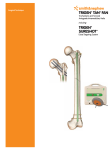
Surgical Technique
Including
1
Surgical Technique for the TRIGEN™ Humeral Nail System
using the TRIGEN SURESHOT™ Distal Targeting System
Table of contents
Introduction....................................................................................... 3
TRIGEN Humeral Nail indications........................................................ 4
TRIGEN SURESHOT indications........................................................... 5
TRIGEN Humeral Nail design rationale............................................... 6
TRIGEN Humeral Nail specifications................................................... 7
Warnings and cautions for TRIGEN SURESHOT ................................ 8
Surgical Technique
Devices for system set up.................................................................. 10
OR preparation.................................................................................... 11
Patient positioning.............................................................................. 13
Instruments for opening the humerus................................................ 14
Incision................................................................................................ 15
Entry Tool and Guide Pin placement.................................................. 16
Instruments fracture reduction and reaming...................................... 17
Prepare proximal section.................................................................... 18
Fracture reduction............................................................................... 19
Measuring implant length................................................................... 20
Additional limited reaming.................................................................. 20
Instruments for nail assembly and insertion...................................... 21
Nail Drill Guide assembly................................................................... 22
TRIGEN SURESHOT system set up..................................................... 23
TRIGEN SURESHOT field accuracy check: optional............................ 24
Nail insertion....................................................................................... 26
Final version adjustment..................................................................... 27
TRIGEN SURESHOT system set up (continued).................................. 28
Devices to lock distally........................................................................ 30
Skin incision with TRIGEN SURESHOT................................................ 31
Targeting the locking hole.................................................................. 32
Drilling the distal hole......................................................................... 33
Screw insertion................................................................................... 34
Instruments for proximal locking, distal locking and freehand
distal locking of Proximal 16cm Humeral Nails................................... 35
Distal locking screws for TRIGEN Proximal 16cm Humeral Nails....... 36
Proximal locking screws..................................................................... 37
Distal locking screws without the use of TRIGEN SURESHOT............ 40
Closure................................................................................................ 41
Removal of the nail............................................................................. 41
TRIGEN SURESHOT Trauma Interface.............................................. 42
TRIGEN SURESHOT Troubleshooting............................................... 46
Catalog information.......................................................................... 48
Nota Bene
The technique description herein is made available to the healthcare professional to illustrate the
authors’ suggested treatment for the uncomplicated procedure. In the final analysis, the preferred
treatment is that which addresses the needs of the patient.
2
Introduction
Uncover an easier and more advanced nailing system
The TRIGEN™ Humeral Nail provides new possibilities for the treatment of proximal
humeral fractures and humeral shaft fractures. With multiplanar screws that are
threaded into the nail to inhibit proximal screw back-out, and effective, simple
instrumentation that helps protect soft tissues, the TRIGEN system now offers an
effective intramedullary nail for humeral fracture management.
3
Introduction
TRIGEN™ Humeral Nail indications
Two-part fractures of the humerus
Three-part fractures of the humerus
Midshaft Diaphyseal Fracture(s)
Segmental Humerus Fracture(s)
4
Introduction
TRIGEN™ SURESHOT™ indications
Legend
Important warnings appear in orange
Tips, tricks and important information appear in blue
Indications, contraindications, intended use and training
The Smith & Nephew TRIGEN SURESHOT Distal Targeting System is intended to be an
intraoperative image-guided localization system. It is a computer-assisted orthopaedic surgery
tool to aid the surgeon with drill positioning for screws during intramedullary nail implantation.
It provides information to the surgeon that is used to place surgical instruments during surgery
utilizing intraoperatively obtained electromagnetic tracking data. The Smith & Nephew TRIGEN
SURESHOT Targeting System V2.1 is indicated for long bone fractures treated with intramedullary
nails in which the use of stereotactic surgery may be appropriate.
An example of a surgical procedure includes but is not limited to locating and drilling the distal
holes in an intramedullary nail.
Contraindications
The screw targeting software application for this system is contraindicated for all IM nails other
than Smith & Nephew TRIGEN META-NAIL™, TAN™, FAN, Humeral, Pediatric and Adolescent nails.
Do not operate the TRIGEN SURESHOT Targeter within 200mm of an installed pacemaker. The
magnetic field produced by the Targeter may interfere with the operation of the pacemaker.
Intended use
The TRIGEN SURESHOT Distal Targeting System is only designed for use with the indicated
implants and instruments. Implants and instruments must be used in accordance with the
instructions, as described in this manual and/or in the non-navigated surgical procedure.
Training
Only trained operators are allowed to use the TRIGEN SURESHOT Distal Targeting System. The
various operating instructions must be fully read and understood as part of the training. If any part
of the instructions is unclear, please contact your local representative.
Plausibility check
As with all technical equipment, malfunctions may occur due to improper use or, more rarely,
technical failure. To reduce the risks involved with such technical malfunction the operation
can be completed using manually controlled instruments, providing the malfunction is detected
without delay.
It is, therefore, important to check the plausibility of the steps, as indicated by the system, and
to carry out verification of the software targeting, particularly when using the system for the first
time. Should there be any doubt regarding correct functioning, the targeting should be verified or a
switch made to a traditional X-Ray technique.
5
Introduction
TRIGEN™ Humeral Nail design rationale
The TRIGEN Humeral Nailing System product
offering includes a 16cm Proximal Straight Nail,
a 16cm Proximal Bent Nail, and a full line of
Long Bent Nails. Nails with a proximal bend are
best suited for simple two-part fractures of the
proximal humerus involving the surgical neck
of the humerus and proximal third humeral
fractures without comminution. In these
scenarios, the proximal bend facilitates
an easier entry portal attainment and nail
insertion with an incision just medial to the
rotator cuff insertion.
The Long Bent Humeral Nail is primarily
indicated for humeral shaft fractures which are
inherently not prone to varus malposition. The
lateral portal design allows insertion just medial
to the rotator cuff insertion and facilitates easier
portal attainment and nail insertion.
TRIGEN 8/7mm X 16cm
Proximal Straight Humeral
Nail offers an alternate
choice in treating different
fracture patterns.
Four multiplanar
proximal locks improve
fracture stability.
4 degree proximal bend
Straight Humeral Nail
The 16cm Proximal Straight Humeral Nail offers
the option of a medialized entry site. If the
greater tuberosity is fractured or compromised,
a straight centralized starting point avoids
fracture extension from the tuberosity fracture
into the entry portal and resultant loss of nail
stability. The entry portal for the straight nail is
slightly more difficult to attain than the curved
nail entry portal.
Long Bent Humeral Nail
Locking holes
5.0mm Cancellous Proximal Locking
Screws; 24mm – 64mm lengths,
2mm increments
4.0mm Cortical Distal Locking Screws;
20mm – 40mm lengths,
2mm increments
Proximal locking holes have
innovative threaded design. Screws
thread into the nail to help prevent
screw back-out.
25°
6
25°
Introduction
TRIGEN™ Humeral Nail specifications
TRIGEN
TRIGEN
TRIGEN
Humeral Nail 8/7mm x 16cm
Proximal Bent Humeral Nail
Humeral Nail 8/7mm x 16cm
Proximal Straight Humeral Nail
Long Bent Humeral Nail 8/7mm, 9/7.5mm,
10/8.5mm Diameter; 18cm – 28cm lengths, by
2cm increments
35mm
Trapezoidal
12mm x 10.5mm
cross section
Trapezoidal
12mm x 10.5mm
cross section
80mm
30mm
Proximal taper
Proximal Taper
20mm
First diameter
measurement: 8mm
First diameter
measurement:
8mm,9mm,
or 10mm
Proximal Taper
Second diameter
Measurement: 7mm
20mm
10mm
Second diameter
measurement:
7mm, 7.5mm,
or 8.5mm
7
Warnings and cautions for TRIGEN™ SURESHOT™
Accessibility of documentation
Please ensure that all instructions are kept in an easily accessible place for operating personnel.
The operator checks and decides
All the information provided by the TRIGEN SURESHOT Distal Targeting System is to help the
operator make decisions during the operation. The operator must check all the suggestions made
by the system and is responsible for all decisions taken.
Responsibility of Smith & Nephew Orthopaedics
In the event of improper use, Smith & Nephew accepts no responsibility or liability whatsoever
for the functioning or utility of the TRIGEN SURESHOT Distal Targeting System when used in the
operating theatre.
Cleaning and sterilization
All instruments must be sterilized before use. Detailed information on the cleaning and sterilization
of components is contained in the separate Cleaning and Sterilization Instructions (Smith & Nephew
document 7138-1339).
Repair or modifications to the system
The user is not permitted to modify or service the equipment. There are no serviceable parts inside
the unit. Refer all service to authorized personnel.
Modifications/additions to the software
The user is not permitted to install or uninstall software. Any new software must be installed by the
manufacturer or by authorized personnel.
It is only allowed to connect equipment to the interface and power supply
connections of the TRIGEN SURESHOT Distal Targeting System which are IEC60601-1 approved
and which are approved by Smith & Nephew Orthopaedics. Do not modify this equipment without
authorization of the manufacturer.
Electrical safety warning
To avoid risk of electric shock, this equipment must only be connected to a supply mains with
protective earth (=ground).
Avoid spilling water or other liquids on electronic/electrical equipment.
Use only Smith & Nephew disposables and accessories with the Smith & Nephew TRIGEN
SURESHOT Distal Targeting System.
Maintenance
To verify accurate functionality, the device should be checked per the Maintenance Instructions
contained in a separate Smith & Nephew document 7118-1927. This accuracy check must be
performed at least once every 12 months.
If this accuracy check is not performed as defined in the previous paragraph, all warranty claims
expire and the device is operated at the user’s own risk.
Recycling
Old electrical and electronic equipment must be disposed separately and may not be included
in the regular domestic waste. Alternatively, the unit can be handed over to Smith & Nephew
Orthopaedics for correct recycling.
8
Warnings and cautions for TRIGEN™ SURESHOT™
Note Do not unplug the power while the
system is running!
Note Danger of damage and tipping over!
Tip Place the unit on a firm, level surface capable
of holding at least 10kg (22 lbs).
Note To avoid the risk of electric shock, this
equipment must only be connected to a supply
mains with protective earth.
9
Devices for TRIGEN™ SURESHOT™ system set up
TRIGEN SURESHOT Targeter
Cat. No. 7169-2801
Trauma Interface
Cat. No. 7169-2802
Power Cord
Cat. No. 6680-0193
Note The Targeter will be operated within the
sterile field and may have contact with the
skin of the patient. The drill sleeve inserts will
be used in the incision and have direct bone
contact.
Note Verify that the Targeter housing is not
damaged (holes, tears, cracks). If the housing
or the connector is damaged, the Targeter is no
longer safe to use.
Note If the Targeter is not recognized after
connection to the system, the Targeter is
defective and must be exchanged. (See also
instrument connection).
Note Broken or damaged instruments must
be exchanged immediately and sent back to
Smith & Nephew, Inc.
Note This device is provided non-sterile and
must be cleaned and sterilized per Cleaning
and Sterilization (Smith & Nephew document
7138-1339) prior to use.
10
Surgical Technique – OR preparation
TRIGEN™ SURESHOT™ system set up
Note This procedure will cover only the specific steps of freehand targeting of intramedullary
locking holes using the TRIGEN SURESHOT Distal Targeting System. For the full surgical procedure,
please refer to the specific surgical technique for the TRIGEN IM Nail System being implanted.
Trauma Interface setup
After the sterile areas have been established,
place the Trauma Interface (7169-2802) in the
desired non-sterile location and turn on the
power switch.
Tip If the Trauma Interface does not power on,
make sure the switch is in the “on” position.
Note No other electrical devices should be
placed near the Trauma Interface. See the
“Guidance and Manufacturer’s Declaration –
Separation Distances” table contained in
Smith & Nephew document 7118-1927.
Pressing the power button will bring up the
start-up screen.
When start-up screen disappears before the
display prompts for tool connections, a warning
screen will appear: Do not operate the TRIGEN
SURESHOT Targeter within 200mm of an
installed pacemaker.
Note The magnetic field produced by the
Targeter may interfere with the operation of
the pacemaker.
11
Surgical Technique – OR preparation
TRIGEN™ SURESHOT™ System set up
TRIGEN SURESHOT Targeter connection
When the display prompts for tool connections,
connect the TRIGEN SURESHOT Targeter
(7169-2801) to the Targeter port on the Trauma
Interface (7169-2802).
Note The Targeter body may have contact with
the patient and must remain in the sterile field
at all times. Only the cable and connector may
be removed from the sterile field.
Note This step needs to be performed at least
ten minutes prior to targeting in order to ensure
proper accuracy.
Tip When oriented as shown, the connector
should assemble easily. Do not force the
connector into the port.
Note If the Targeter is properly connected to
the system and the application remains in this
screen for more than 30 seconds, the Targeter
may have been damaged during cleaning/
sterilization. In this case another Targeter has to
Targeter and probe have not been connected be used.
Tip It is possible at any time to disconnect and
reconnect tools when the application is running.
The display will show a screen reporting the
missing instrument.
Confirmation that the Targeter tool has
been connected when the center of the
Targeter lights up orange.
12
Surgical Technique
Patient positioning
Supine position
Position the patient supine with three liter bags
of saline between scapulas. Tilt the patient on
the fluoroimage table so that the humerus may
be extended posteriorly.
The C-arm may be positioned either superior
to the shoulder or opposite the shoulder if the
C-arm modus is large enough.
Alternative position
Position the patient in a slight “beach-chair”
position. The arm of the semi-recumbent
patient is left to hang near the trunk thus its
weight helps reposition the humeral head
anterior to the acromion. The C-arm is placed
above the head of the table at 30° extending
distally over the shoulder. This will allow an
anteroposterior view of the humerus. The arm
should be placed in reverse pushing position
to clear the entry point, anatomically located at
the superior margin of the articular surface just
medial to the greater tuberosity.
Once the correct positioning and imaging
are assured, the shoulder and arm are
prepped and draped.
13
Surgical Technique
Instruments for opening the humerus
Entry Cuff Guard
Cat. No. 7175-1100
Disposable Cuff Guard
(Optional – may be used in place of
7175-1100 Entry Cuff Guard)
Cat. No. 7175-1101
3.2mm Tip Threaded Guide Pin
Cat. No. 7175-1147
Trocar
Cat. No. 7175-1136
Mini Connector with Handle
Cat. No. 7175-1137
Straight Entry Reamer
Cat. No. 7175-1103
Cannulated Awl
Cat. No. 7175-1102
Straight Ratcheting Driver
Cat. No. 7175-1141
14
Surgical Technique
Incision
The incision approach that is recommended
and most often used for antegrade humeral
nailing is the lateral deltoid splitting incision. For
complete fractures or nonunions, a traditional
deltopectoral approach may be used.
A 2-3cm incision is made from the edge of the
acromion to the edge of the head of humerus,
anterolateral to the tip of the acromion. The
deltoid is divided down to the sub-deltoid bursa.
The deltoid muscle is then retracted. Visualize
the rotator cuff insertion into the greater
tuberosity. The biceps tendon is palpated
anteriorly. The rotator cuff supraspinatus tendon
is incised 15-20mm in line with its fibers,
exposing the humeral head. Insert suture into
the rotator cuff interval to retract the rotator cuff
and facilitate its repair after insertion of the nail.
Lateral portal
Entry portal is made just medial to the tendon
insertion and centered midway between the
biceps groove anteriorly and the posterior
humeral head.
Central portal (straight proximal nail)
Entry portal is made at the apex of the
humeral head and centered midway between
the biceps groove anteriorly and the posterior
humeral head.
Central Portal
Lateral Portal
15
Surgical Technique
Entry Tool and Guide Pin placement
The rotator cuff is divided to expose the
superior portion of the humeral head. The Entry
Cuff Guard (7175-1100) protective device should
be used to retract the soft tissue of the rotator
cuff for visualization of the bone. The Cuff
Guard provides a visual working channel, while
protecting the rotator cuff and soft tissue during
the procedure.
Attach the 3.2mm Tip Threaded Guide Pin (71751147) or Trocar (7175-1136) to the Mini Connector
with Handle (7175-1133). Place through the Cuff
Guard into the superior margin of the humeral
head just medial to the greater tuberosity,
avoiding the rotator cuff insertion.
Verify position on the C-arm to confirm guide
pin placement is aligned in the medullary canal
by oblique pictures at 45° with internal and
external rotation of the shoulder.
Note The Disposable Cuff Guard (7175-1101) may
be used to protect the rotator cuff while preparing
the humerus for the nail. The Nail can be inserted
through the Disposable Cuff Guard. A Drill Guide
comes packaged with the Disposable Cuff Guard
to facilitate the placement of the guide pin in the
precise position.
16
Surgical Technique
Instruments fracture reduction and reaming
Straight Reducer
Cat. No. 7175-1105
Straight Ratcheting Driver
Cat. No. 7175-1141
2.0mm Graduated Ball Tip Guide Rod
Cat. No. 7175-1146
Obturator
Cat. No. 7175-1145
Ruler
Cat. No. 7175-1126
Fixed Endcutting Reamers (image not shown)
Cat. No. 7111-8220 to 7111-8230
Straight entry reamer
Cat. No. 7175-1103
Cannulated Awl
Cat. No. 7175-1102
17
Surgical Technique
Prepare proximal section
Insert the Straight Entry Reamer (7175-1103) over
the 3.2mm Tip Threaded Guide Pin (7175-1147)
or the Trocar (7175-1136) through the Entry Cuff
Guard (7175-1100) and/or the Disposable Cuff
Guard (7175-1101) to prepare the humerus for
the proximal section of the nail. Ream until the
cutting teeth are just below the articular surface
of the humeral head. The depth indicator on
the reamer should be level with the top of the
Cuff Guard.
Alternatively, the Cannulated Awl (7175-1102)
can be used with the Straight Ratcheting Driver
(7175-1141).
18
Surgical Technique
Fracture reduction
After removing the Straight Entry Reamer
(7175-1103) and 3.2mm Tip Threaded Guide
Pin (7175-1147) or Trocar (7175-1136), insert the
Straight Reducer (7175-1105) attached to the
Straight Ratcheting Driver (7175-1141) with the
slot oriented toward the lateral cortex and
reduce the fracture. Place the tip of the finger off
the medial cortex to help reduce the fracture.
To maintain reduction, introduce the 2.0mm
Graduated Ball Tip Guide Rod (7175-1146)
through the Straight Reducer. Center the Guide
Rod 1-2cm proximal to the olecranon fossa in
the distal end of the humerus. Once the Guide
Rod is in place, carefully remove the Straight
Reducer, using the Obturator (7175-1145) as
needed to ensure the Guide Rod stays in place.
19
Surgical Technique
Measuring implant length
To measure the length of the implant needed,
ensure that the distal tip of the 2.0mm
Graduated Ball Tip Guide Rod (7175-1146) is
located at the desired position of the distal tip
of the nail. Slide the Ruler (7175-1126) over the
proximal end of the 2.0mm Graduated Ball
Tip Guide Rod and advance the open end of
the Ruler to where the proximal portion of the
implant will be seated, just below the articular
surface of the proximal humerus. Read the nail
length from the calibrations exposed at the
other end of the Ruler.
The 2.0mm Graduated Ball Tip Guide Rod
has graduated markings and can be used to
determine required implant length. The Straight
Reducer (7175-1105) can also be used to
determine implant length, by using the markings
on the reducer shaft. Both options are used
to directly measure to the articular surface,
taking care to ensure the nail will be slightly
countersunk.
Additional limited reaming
(Necessary for Proximal Nails longer than
8mm X 16cm)
After the nail length has been determined,
additional limited reaming can be performed to
avoid nail incarceration and distraction at the
fracture site during insertion of the nail. Begin
with the 6.0mm Fixed Endcutting Reamer
(7111-8220 to 7111-8230) and insert it over
the 2.0mm Graduated Ball Tip Guide Rod.
Ream the intramedullary canal sequentially.
Be careful not to “push” the guide rod distally
during reaming. Never insert a nail that has a
larger diameter than the last reamer used.
It is recommended that templating is done for
all cases to estimate the size of the implant
needed. The diameter of the last reamer used
will help determine the diameter of the implant
needed. Keep in mind that all of the nail sizes
taper, and the canal should be reamed to 1mm
over the implant diameter.
20
Surgical Technique
Instruments for nail assembly and insertion
Humeral Nail Guide Bolt
Cat. No. 7175-1108
Nail Drill Guide
Cat. No. 7175-1129
Guide Bolt Wrench
Cat. No. 7175-1134
Impactor
Cat. No. 7175-1133
Proximal Drop
Cat. No. 7175-1131
Gold Outer Sleeve
Cat. No. 7175-1128
3.2mm Silver Inner Drill Sleeve
Cat. No. 7175-1116
3.2mm Long Graduated Two-Flute Drill
Cat. No. 7175-1149
Anterior Stylus
Cat. No. 7175-1130
Trocar
Cat. No. 7175-1136
Humeral Nail Drill Guide Probe
Cat. No. 7175-1151
21
Surgical Technique
Nail Drill Guide assembly
Once the implant selection is complete, use the
Humeral Nail Guide Bolt (7175-1108) to attach the
Nail Drill Guide (7175-1129) to the nail. The nail
and Nail Drill Guide are keyed to ensure proper
orientation of the nail on the Nail Drill Guide.
Note The metal threads on the proximal locking
holes should always be lateral. Tighten the
Humeral Nail Guide Bolt using the Guide Bolt
Wrench (7175-1134). The Impactor (7175-1133) is
then attached to the Humeral Nail Guide Bolt.
To complete the assembly, attach the Proximal
Drop (7175-1131) to the lateral arm of the Nail
Drill Guide. Tighten the Proximal Drop to the
Guide using the knurled knob. Verify targeting
accuracy by inserting a Gold Outer Sleeve (71751128) and 3.2mm Silver Inner Drill Sleeve (71751116) into the drop and passing a 3.2mm Long
Graduated Two-Flute Drill (7175-1149) through
the assembly. An incorrectly attached nail will
not target. The Proximal Drop should be used to
target the proximal screws on all Humeral Nails,
and the distal screws on the 16cm Proximal
Nails. Distal locking screws for the 18cm or
longer Humeral Nails should be targeted using
the TRIGEN™ SURESHOT™ Distal Targeting System
or a freehand technique.
Note See page 24 for the field accuracy.
Note Remove Targeter prior to Nail insertion.
Check with the TRIGEN SURESHOT Distal
Targeting System.
22
The Humeral Nail and Nail Drill
Guide are keyed to ensure
proper orientation of the nail on
the Nail Drill Guide.
Surgical Technique
TRIGEN™ SURESHOT™ system set up (continued)
Locking hole accuracy check in the
operative field
Insert the SURESHOT Humeral Drill Guide Probe
(7169-1152) with the assembled SURESHOT
Humeral Set Stop (7169-1151) through the Nail
Drill Guide (7175-1129) and cannulation of the
TRIGEN IM nail.
Picture shown with
TRIGEN META-NAIL™
Tip The back of a standard AO Mini Connector
(7175-1153) may be used as a lever to release
the set stop from the drill guide if overtightened.
Note Verify the set stop position and nail length
match, align the drill sleeve with one of the
distal holes of the nail. Verify on the display
that the representation of the nail/drill sleeve
is true. Remove the probe from inside the nail
and begin nail insertion. Take off set stop before
inserting the nail and place the impactor.
Note Verify the probe is oriented correctly in
the set stop (notches should face anteriorly). If
the probe is rotated 180°, it will not be accurate.
Note The probe is bent for easier insertion. Do
not straighten it as this may cause inaccuracy or
even missing the lock.
Note All tool cables should be uncoiled
completely and any excess cables should be
kept out of the targeter measurement volume.
Note To guarantee system accuracy, the
accuracy check has to be performed directly
in the operative field.
23
Surgical Technique
TRIGEN™ SURESHOT™ field accuracy check: optional
A field accuracy check procedure should be
performed at least once a year or whenever the
accuracy of a TRIGEN SURESHOT Humeral Drill
Guide Probe (7169-1152) or TRIGEN SURESHOT
Targeter (7169-2801) needs to be verified. This
procedure can also be performed during surgery
to verify all components are working correctly
prior to their use on a patient.
Field accuracy check steps
Attach TRIGEN SURESHOT Field Accuracy Gauge
(7169-2808) to TRIGEN SURESHOT Targeter. The
knob on the Field Accuracy Gauge should be
hand tightened only.
1
2 Attach the TRIGEN SURESHOT META Set Stop
(7169-2806) to the end of the Field Accuracy
Gauge, insert a TRIGEN SURESHOT probe into
the set stop and set the depth to the “REF” mark
on the probe body.
3 From the software “Menu” button, select “Field
Check” option.
24
Surgical Technique
TRIGEN™ SURESHOT™ field accuracy check: optional
4 A software window will appear informing
the user if the TRIGEN SURESHOT Targeter
(7169-2801) and SURESHOT Humeral Drill Guide
Probe (7169-1152) combination is within the
predefined accuracy parameters (“Pass” or
“Fail” message).
5 If the field accuracy check fails, check the
“Troubleshooting” section of this document for
possible solutions.
Note This step should be performed at least
once a year to ensure that the device is
working properly.
25
Surgical Technique
Nail insertion
At this point the nail is ready to be inserted.
Care should be taken to insert the nail with the
correct amount of retroversion and depth in
order to maximize locking screw fixation while
avoiding critical soft tissues such as the biceps
tendon, axillary and radial nerves.
Insert the nail attached to the Nail Drill Guide
Assembly over the 2.0mm Graduated Ball Tip
Guide Rod (7175-1146) and through the Entry
Cuff Guard (7175-1100) with the lateral arm of the
drill guide oriented with approximately 30-35° of
retroversion. Adjustments to this version can be
made so that the anterior arm of the drill guide
is in line with the lesser tuberosity, avoiding
alignment with the bicipital groove. Proper depth
is achieved when the lateral ledge on the drill
guide is above the lateral cortex and the nail is
seated just below the articular surface.
Remove the Guide Rod from the top of the Nail
Drill Guide (7175-1129). Confirm that the fracture
is compacted and not distracted.
26
Surgical Technique
Final version adjustment
Final and rigid version adjustment to the nail
can be performed prior to inserting the proximal
locking screws by attaching the Anterior Stylus
(7175-1130) to the anterior arm of the Nail Drill
Guide (7175-1129).
Insert the Trocar (7175-1136) through the Anterior
Stylus and position the nail so that the Trocar
can be inserted into the lesser tuberosity at the
location of the anterior locking hole. Leave the
Trocar in place to maintain fracture reduction
and rotational stability during the insertion of the
proximal lateral screws.
This step ensures that the proximal anterior and
proximal anterolateral locking screws will not
be inserted into the bicipital groove, potentially
injuring the biceps tendon (Figure 16b).
Note When using the TRIGEN™ SURESHOT™ Distal
Targeting System, move the Anterior Stylus (71751130) to the lateral side of the Proximal Drop
(7175-1131) after the final version is determined
and insert a 3.2mm Tip Threaded Guide Pin
(7175-1147) to provisionally secure the nail.
27
Surgical Technique
TRIGEN™ SURESHOT™ system set up (continued)
Connect probe to Trauma Interface (7169-2802)
unit. Make sure to use the SURESHOT Humeral
Drill Guide Probe [Dark Green] (7169-1152).
Connect the probe to either of the probe sensor
ports on the Trauma Interface.
Note For assembly, screw on SURESHOT
Humeral Set Stop (7169-1151) to Nail Drill Guide
(7175-1129), then insert probe.
Note The probe will be used as an
intramedullary tool inside the nail placed in the
patient’s bone.
Note If the probe is not recognized after
connection to the system, the probe is
defective and must be exchanged. (See also
instrument connection).
Note Broken or damaged instruments must
be exchanged immediately and sent back to
Smith & Nephew.
Note This device is provided sterile by ethylene
oxide gas and is single use.
There will be a confirmation in the screen of the
Trauma Interface that implies that the probe has
been connected.
Tip When oriented as shown, the connector
should assemble easily. Do not force the
connector into the port.
Note If the probe is properly connected to the
system and the application reports “Probe not
found” for more than 10 seconds, the probe
may be damaged or defective. In this case, the
probe has to be exchanged.
Tip It is possible at any time to disconnect and
reconnect tools when the application is running.
The display will show a screen reporting the
missing instrument.
28
Dark green probe
Use only with TRIGEN Humeral Nail
Proximal Drop (7175-1151)
Surgical Technique
TRIGEN™ SURESHOT™ system set up (continued)
After the TRIGEN SURESHOT Targeter (7169-2801)
and SURESHOT Humeral Drill Guide Probe
(7169-1152) have been connected, attach
SURESHOT Humeral 3.2mm Drill Sleeve
(7169-1154) to targeter.
Drill sleeve attachment
Tightly secure the selected drill sleeve to
the targeter.
Tip The drill sleeve (7169-1154) can be loosened
from the targeter using the slot in the Small
Hammer (7175-1135).
Select the TRIGEN Humeral nail size that will
be used.
Tip A different TRIGEN Humeral Nail size can be
selected at any time during the procedure by
choosing the implant option from the drop down
menu. The selected implant and diameter will
be noted on the Trauma Interface screen.
29
Surgical Technique
Devices to lock distally
TRIGEN™ SURESHOT™ Targeter
Cat. No. 7169-2801
Trauma Interface
Cat. No. 7169-2802
Power Cord
Cat. No. 6680-0193
SURESHOT Humeral 3.2mm AO Drill
Cat. No. 7169-1155
New image coming
TRIGEN SURESHOT Humeral Drill Sleeve
Cat. No. 7169-1154
SURESHOT Humeral Drill Guide Probe
Cat. No. 7169-1152
SURESHOT Humeral 3.5mm Hexdriver
Note When the targeter is out of the preferred
Cat. No. 7169-1153
range or there is metal or electrical interference,
the green and red targeter circles on the
Trauma Interface screen may become unstable
and/or a warning message will be displayed. If
the interference is excessive, the IM nail image
on the Trauma Interface screen will disappear.
If interference cannot be avoided, a standard
X-Ray technique must be used.
Note All tool cables should be uncoiled
completely and any excess cables should be
kept out of the targeter measurement volume.
Straight Ratcheting Driver
Cat. No. 7175-1141
SURESHOT Humeral Set Stop
Cat. No. 7169-1151
30
Surgical Technique
Skin incision with TRIGEN™ SURESHOT™
Detach the Impactor (7175-1133) from the Nail
Drill Guide (7175-1129). Reattach the SURESHOT
Humeral Set Stop (7169-1151) and insert the
SURESHOT Humeral Drill Guide Probe (71691152) in the nail. Adjust the probe to nail length.
Skin incision
Use the serrated tip of the SURESHOT Humeral
3.2mm Drill Sleeve (7169-1154) to identify where
to make the incision. The tip is at the right
position when the green circle is aligned with
the desired hole on screen.
Make the incision and place the tip of the drill
sleeve down to bone where the green circle is
aligned directly over the hole on the screen.
Note No X-Rays are necessary.
31
Surgical Technique
Targeting the locking hole
With the TRIGEN™ SURESHOT™ Humeral 3.2mm
AO Drill (7169-1155) inserted into the TRIGEN
SURESHOT Targeter (7169-2801), insert the tip
of the SURESHOT Humeral 3.2mm Drill Sleeve
(7169-1154) (represented by the green circle)
through the incision and down to bone.
Critical Verify there are no other metal objects
(including metal triangles) in the field. Metal
interference will cause the system to be
inaccurate.
Tibia shown
in image
Perfect circles
Align the tip of the drill sleeve over the desired
hole in the nail. This will be represented on
the screen when the green circle is centered in
the hole as shown. Push the serrated tip firmly
against bone to keep the green circle static on
the screen.
Adjust the trajectory (represented by red line
between two circles) of the red circle until both
circles are concentric and centered with the
desired hole on the screen. Then start drilling.
Note The green circle must be fully within the
hole of the IM nail displayed on the Trauma
Interface screen to ensure accurate drilling.
32
Surgical Technique
Drilling distal hole
Drill through near cortex and the nail using the
TRIGEN™ SURESHOT™ Humeral 3.2mm AO Drill
(7169-1155). Before drilling through far cortex,
obtain the screw measurement.
Picture shown with
TRIGEN META-NAIL™
Note Important: if standard 3.2mm Graduated
Two-Flute Drill is used, magnetic metal can
adversely affect accuracy causing the drill to
miss. Verify there is no other magnetic metal
object in area other than the items shown.
A note will appear on screen warning of
compromised targeting field, if magnetic metal
is close. If it is in the field, image disappears.
Screw measurement
With the tip of the drill against the far cortex,
measure for length, then drill through the far
cortex. Ensure the serrated tip of the SURESHOT
Humeral 3.2mm Drill Sleeve (7169-1154) is
pushed against the bone.
Example
Measure 35mm, add approximately 3mm, the
screw length would be 38mm.
Alternative screw measurement with Screw
Depth Gauge (7175-1139).
After successfully drilling through the screw
hole of the nail with the SURESHOT Humeral
3.2mm AO Drill, remove the drill bit being
careful not to move the arm.
33
Surgical Technique
Screw insertion
Detach the SURESHOT Humeral 3.2mm Drill
Sleeve (7169-1154) from the TRIGEN™ SURESHOT™
Targeter (7169-2801). Introduce the SURESHOT
Humeral 3.5mm Hexdriver (7169-1153) with the
screw attached through the Targeter.
TRIGEN SURESHOT Targeter is backed away
from bone by sleeve length, approximately
80mm for the sleeve.
Note Image disappears if too close.
Note The standard TRIGEN Hexdrivers are
made from magnetic stainless steel that will
cause interference with the system and cannot
be used.
Insert a 4.0mm Self-Tapping Cortical Screw
into the pre-drilled hole through the nail, and
through the far cortex.
Before fully inserting the screw, remove power
drill and Targeter. Final screw seating must
be done by hand by attaching the Straight
Ratcheting Driver (7175-1141) to the SURESHOT
Humeral 3.5mm Hexdriver (7169-1153).
The depth of the screw can be verified by
placing a Gold Outer Sleeve (7175-1128) down
to bone over the hexdriver. There is a profile of
the screw head and a groove on the hexdriver
that may be used as an indicator for the position
of the screw head relative to the near cortex.
Positioning of the screw can be verified with
the C-arm.
Repeat with other distal screws.
Note Remove SURESHOT Humeral Drill Guide
Probe (7169-1152) before proceeding to proximal
locking. Remove the probe from the SURESHOT
Humeral Set Stop (7169-1151). Detach set stop
from the Nail Drill Guide (7175-1129). Do not pull
the cable to remove probe.
34
Picture shown with
TRIGEN META-NAIL™
Surgical Technique
Instruments for proximal locking, distal locking of Proximal 16cm
Humeral Nails and freehand distal locking
Proximal Drop
Cat. No. 7175-1131
Nail Drill Guide
Cat. No. 7175-1129
3.2mm Silver Inner Drill Sleeve
Cat. No. 7175-1116
Gold Outer Sleeve
Cat. No. 7175-1128
Trocar
Cat. No. 7175-1136
3.2mm Long Graduated Two-Flute Drill
Cat. No. 7175-1149
Screw Depth Gauge
Cat. No. 7175-1139
3.5mm Hex Driver
Cat. No. 7175-1140
Straight Ratcheting Driver
Cat. No. 7175-1141
Screw Length Sleeve
Cat. No. 11-0238
35
Surgical Technique
Distal locking screws for TRIGEN™ Proximal 16cm Humeral Nails
Note The Proximal Drop (7175-1131) only targets
the distal holes for the 16cm nails. Nails longer
than 16cm will be targeted using the freehand
technique or TRIGEN SURESHOT™ Distal
Targeting System.
With the Proximal Drop connected to the lateral
arm of the Nail Drill Guide (7175-1129), place the
3.2mm Silver Inner Drill Sleeve (7175-1116) into
the Gold Outer Sleeve (7175-1128). Insert the
sleeve unit into the targeting hole in the Proximal
Drop which corresponds to the superior M/L
distal locking hole in the nail. While applying
compression at the condyles of the elbow to
reduce shaft fractures as needed, make a stab
incision and push the sleeve unit down to the
bone. The Trocar (7175-1136), in combination
with the drill sleeve unit, may be used to dimple
the cortex. Drill through both cortices using the
3.2mm Long Graduated Two-Flute Drill (7175-1149).
A length measurement can be taken from the
calibrations on the drill against the 3.2mm Silver
Inner Drill Sleeve, or the Screw Depth Gauge
(7175-1139) can be used through the Gold Outer
Sleeve to measure for distal locking screws.
Once the appropriate length 4.0mm SelfTapping Cortical Screw is selected, it is attached
to the 3.5mm Hex Driver. The screw is inserted
through the Gold Outer Sleeve using the 3.5mm
Hex Driver (7175-1140). The head of the screw
should be nearly seated when the laser-marked
ring on the Hex Driver is even with the Gold
Outer Sleeve. Final tightening of the screw
should always be performed manually using the
Straight Ratcheting Driver (7175-1141). Repeat
this process for the inferior distal screw.
36
Surgical Technique
Proximal locking screws
Caution Do not countersink the nail such that
proximal locking screws are below the level
of the humeral head to avoid damage to the
axillary nerve.
In order to avoid impingement of the biceps
tendon, it is a good idea to start with the
proximal anterolateral locking screw. Place the
3.2mm Silver Inner Drill Sleeve (7175-1116) into
the Gold Outer Sleeve (7175-1128). Insert the
sleeve unit into the Proximal Drop (7175-1131).
The Trocar (7175-1136) can be inserted into the
sleeve unit to determine the exact location for
the insertion of the locking screw. If the Trocar
tip indicates the proximal anterolateral screw is
in line with the bicipital groove, reorient the nail
to avoid impingement. Once proper alignment
has been achieved, make a stab incision and
push the sleeve unit down to the bone. Use the
Trocar to dimple the cortex. Remove the Trocar
from the sleeve unit and drill through the near
cortex, stopping at the articular surface of the
far cortex using the 3.2mm Graduated Two-Flute
Drill (7175-1149). Take the length measurement
from the calibrations on the drill or the Screw
Depth Gauge (7175-1139). The 3.2mm Silver
Inner Drill Sleeve must be removed from the
Gold Outer Sleeve in order to use the Screw
Depth Gauge.
37
Surgical Technique
Proximal locking screws
Remove the 3.2mm Silver Inner Drill Sleeve
(7175-1116) and insert the 3.5mm Hex Driver
(7175-1140) with the appropriate length 5.0mm
Cancellous Screw attached. The head of
the screw should be nearly seated when
the laser marked ring on the 3.5mm Hex
Driver is even with the Gold Outer Sleeve
(7175-1128). Final seating of the screw should
always be under manual control using the
Straight Ratcheting Driver (7175-1141) to avoid
over insertion of the screw in soft bone.
Insert the remaining two proximal locking
screws.
38
Surgical Technique
Proximal locking screws
To target the proximal anterior locking hole,
remove the Anterior Stylus (7175-1130) and
attach the Proximal Drop (7175-1131) on the
anterior arm of the Nail Drill Guide (7175-1129).
Caution Locate biceps tendon prior to
beginning placement of the anterior screw.
Insert the 3.2mm Silver Inner Drill Sleeve
(7175-1116) into the Gold Outer Sleeve
(7175-1128). Insert the sleeve unit into the
hole marked “Anterior” on the Proximal Drop.
Follow the same procedure described previously
to drill, measure and insert the Anterior and
Posterior Proximal Screws.
39
Surgical Technique
Distal locking screws without the use of TRIGEN™ SURESHOT™
Freehand locking
Distal locks on all nails 18cm and longer should
be done using the freehand technique. The
Screw Length Sleeve (11-0238) can be used
with the 3.2mm Graduated Two-Flute Drill
(7175-1149) to drill for the A/P distal locks.
Length measurements can be made by using
the graduations on the drill against the Screw
Length Sleeve. The Screw Depth Gauge (71751139) could also be used to determine the
appropriate screw length. Once the appropriate
length 4.0mm Self-Tapping Cortical Screw is
selected, it is attached to the 3.5mm Hex Driver
(7175-1140). The screw is inserted through
the Gold Outer Sleeve (7175-1128) using the
3.5mm Hex Driver. Final tightening of the screw
should always be performed manually using the
Straight Ratcheting Driver (7175-1141). Repeat
this process for the inferior distal screw.
40
Surgical Technique
Closure
Close the wound in layers, use nonresorbable
sutures in the rotator cuff repair. Close the
remainder of the incision in a standard fashion.
Removal of the nail
The Screw Head Trephine (7175-1144), the
Proximal Nail Trephine (7175-1143) and the
Extractor (7175-1142) are included in the
instrument set to facilitate nail removal.
41
TRIGEN™ SURESHOT™ Trauma Interface
Overview mode
When the Targeter is greater than 5cm from the
interlocking holes, the Trauma Interface screen
will display the IM nail in the overview mode.
This provides the user with a larger field of view
in order to help find the general location of the
interlocking holes.
The view in the upper right corner is the profile
view. It is collinear to the drill sleeve axis
and the position is aligned with the tip of the
drill sleeve.
Drilling mode
When the targeter is moved within 5cm of the
interlocking holes, the Trauma Interface screen
will display the IM nail in the drilling mode.
This provides the user with a smaller field
of view that automatically zooms in to the
interlocking holes.
Drilling mode manual rotation
Each IM nail has several predefined views
that are automatically selected depending
on the position of the Targeter to the IM nail.
Depending on the operating environment, these
predefined views might not be appropriate and
can be manually adjusted.
To rotate the view
Touch the screen near the outside and
“drag” the view in a clockwise or
counterclockwise direction.
To flip the view
Touch the “Menu” button and select “Toggle
Back View.”
All changes made for a view are temporarily
stored for that view until program exit.
To reset the view
The default view settings can be restored by
touching the “Menu” button and selecting
“Reset View” or double tapping the center of
the screen.
42
TRIGEN™ SURESHOT™ Trauma Interface
Menu
Tapping on the Menu button will open up
several Menu options.
Toggle back view
This view may be used in cases where the
Trauma Interface cannot be placed in front of
the surgeon. It is intended to be used similar
to the mirror option commonly available on
C-arm machines.
Implant
When choosing an implant, several options are
given. Tap on screen to select.
Drill sleeve
The 3.2mm Humeral Drill Sleeve appears on the
screen of the Interface.
43
TRIGEN™ SURESHOT™ Trauma Interface
Field check
Fail screen, meaning that something is not
targeting correctly. See “Troubleshooting”
section for further information.
Pass screen
When targeting correctly, a “pass screen”
will occur.
About
The “About screen” provides more information
about the software used.
Shutdown
Tap on screen to shut down the system before
flipping the power switch.
44
TRIGEN™ SURESHOT™ Trauma Interface
Error message
An error message will occur, if a probe-sensor
is invalid or broken.
45
TRIGEN™ SURESHOT™ Troubleshooting
Problem
Trauma Interface unit is
without power
Possible cause
Mains power plug is not
inserted (properly) or there is
no mains power
No power on the wall outlet
One or both mains power
fuses are blown
Buttons or items are difficult to Touchscreen is de-calibrated
select on the touchscreen
Suggested action
Insert mains power plug into
reliable power supply
Try other power outlet
Replace mains fuses
Damaged VGA cable
Access calibration software by
selecting “Maintenance” from
the “About” option under the
“Menu” options (password
required)
Connect VGA cable to both
Trauma Interface and video
monitor before powering on
Trauma Interface
Replace VGA cable
Video monitor not on correct
input
Select proper input on video
monitor
Probe not recognized
Error reading data from
Targeter
Damaged Targeter
Error reading data from probe
Probe will not insert to the
proper depth in the nail
Damaged probe
Obstruction within the nail
cannulation
Unplug Targeter wait
10 seconds, plug back in
Replace Targeter with new unit
Unplug probe, wait 10 seconds,
plug back in
Replace probe with new unit
Re-insert the ball tip guide rod
into the nail cannulation to
clear any obstruction
Remove any metal objects from
the targeting field
VGA video out not functioning
TRIGEN SURESHOT Targeter
not recognized
Nail not visible on the screen
46
VGA port not activated on
Trauma Interface
Metal interference
within the TRIGEN SURESHOT
electromagnetic field
TRIGEN SURESHOT Targeter
and probe not within range of
each other
Move the TRIGEN SURESHOT
Targeter closer to the sensor
end of the probe
TRIGEN™ SURESHOT™ Troubleshooting
Problem
Red and Green targeting
circles representing the drill
sleeve appear incorrect
Possible cause
Incorrect drill sleeve length
selected
Metal interference within
the TRIGEN SURESHOT
electromagnetic field
Probe not inserted correctly
within set stop
Damaged probe
Targeting missed the
intended hole
Metal interference
within the TRIGEN SURESHOT
electromagnetic field
Probe not inserted correctly
within set stop
Damaged probe
Drill sleeve cannot be
removed from TRIGEN
SURESHOT Targeter
Over-tightening of drill sleeve
The 4.7mm/4.0mm step
drill will not fit through the
drill sleeve
Not compatible with the
TRIGEN SURESHOT Distal
Targeting System
Suggested action
Verify the correct drill sleeve
length is selected from the
software menu
Remove any metal objects
from the targeting field
Verify probe is oriented
and seated correctly in the
notches of the set stop
Verify probe accuracy with
Field Accuracy Gauge
Remove any metal objects from
the targeting field
Verify probe is oriented and
seated correctly in the notches
of the set stop
Verify probe accuracy with
Field Accuracy Gauge
Use the Slotted Hammer from
the instrument tray as a wrench
to unscrew the drill sleeve
counter-clockwise from
the Targeter
Only use the long (7169-2811),
short (7169-2810) or 3.2mm
SURESHOT Humeral Drill (71691155) drills designated for use
with the TRIGEN SURESHOT
Distal Targeting System
47
Catalog information
TRIGEN™ Humeral Nail Implants
TRIGEN Humeral Nail Cap
(Not Shown)
Cat. No.
7176-0000
TRIGEN Proximal Straight Humeral Nail
Cat. No.
Size
7176-0816 8/7mm
Length
16cm
TRIGEN Proximal Bent Humeral Nail
Cat. No.
Size
7177-0816 8/7mm Length
16cm
TRIGEN Long Bent Humeral Nail
Cat. No.
7177-0818 7177-0820 7177-0822 7177-0824 7177-0826 7177-0828 7177-0918 7177-0920 7177-0922 Size
8/7mm 8/7mm 8/7mm 8/7mm 8/7mm 8/7mm 9/7.5mm 9/7.5mm 9/7.5mm Length
18cm 20cm 22cm 24cm 26cm 28cm 18cm 20cm 22cm Cat. No.
7177-0924 7177-0926 7177-0928 7177-1018 7177-1020 7177-1022 7177-1024 7177-1026 7177-1028 Size
Length
9/7.5mm 24cm 9/7.5mm 26cm 9/7.5mm 28cm
10/8.5mm 18cm 10/8.5mm 20cm 10/8.5mm 22cm
10/8.5mm 24cm 10/8.5mm 26cm 10/8.5mm 28cm 5.0mm Self-Tapping Cancellous Screw
Cat. No.
7175-5024
7175-5026
7175-5028
7175-5030
7175-5032
7175-5034
7175-5036
7175-5038
7175-5040
7175-5042
7175-5044
Length
24mm
26mm
28mm
30mm
32mm
34mm
36mm
38mm
40mm
42mm
44mm
Cat. No.
7175-5046
7175-5048
7175-5050
7175-5052
7175-5054
7175-5056
7175-5058
7175-5060
7175-5062
7175-5064
Length
46mm
48mm
50mm
52mm
54mm
56mm
58mm
60mm
62mm
64mm
4.0mm Self-Tapping Cortical Screw
Cat. No.
7175-4020
7175-4022
7175-4024
7175-4026
7175-4028
7175-4030
48
Length
20mm 22mm 24mm 26mm 28mm 30mm
Cat. No.
7175-4032
7175-4034
7175-4036
7175-4038
7175-4040
Length
32mm 34mm 36mm 38mm 40mm
Catalog information
TRIGEN™ Humeral Nail Instruments
TRIGEN Humeral Nail Instrument Set
Set No. 7175-1150
Entry Cuff Guard
Cat. No.
7175-1100
Disposable Cuff Guard
Cat. No.
7175-1101
3.2mm Tip Threaded Guide Pin
Cat. No.
Trocar
Cat. No.
7175-1147
7175-1136
Mini Connector with Handle
Cat. No.
7175-1137
Straight Entry Reamer
Cat. No.
7175-1103
Small Hammer
Cat. No.
7175-1135
Humeral Nail Guide Bolt
Cat. No.
7175-1108
Nail Drill Guide
Cat. No.
7175-1129
Guide Bolt Wrench
Cat. No.
7175-1134
49
Catalog information
TRIGEN™ Humeral Nail Instruments
Impactor
Cat. No.
7175-1133
Straight Reducer
Cat. No.
7175-1105
Straight Ratcheting Driver
Cat. No.
7175-1141
*2.0mm x 600mm Graduated 3.2mm Ball Tip
Guide Rod
Cat. No.
7175-1146
Obturator
Cat. No.
Ruler
Cat. No.
7175-1145
7175-1126
Fixed Endcutting Reamers
image not shown
Size
6.0mm
7.0mm
8.0mm
9.0mm
10.0mm
11.0mm
Cat. No.
7111-8220
7111-8222
7111-8224
7111-8226
7111-8228
7111-8230
Proximal Drop
Cat. No.
7175-1131
Anterior Stylus
Cat. No.
7175-1130
3.2mm Silver Inner Drill Sleeve
Cat. No.
7175-1116
*Dedicated to Humeral nail only, cannot be used with other TRIGEN systems (HFN) 50
Catalog information
TRIGEN™ Humeral Nail Instruments
Gold Outer Sleeve
Cat. No.
7175-1128
3.2mm Graduated Two-Flute Drill
Description Cat. No.
Short
7175-1148
Long
7175-1149
Screw Depth Gauge
Cat. No.
7175-1139
3.5mm Hex Driver
Cat. No.
7175-1140
AO Mini Connector
Cat. No.
7175-1153
Mini Connector
Cat. No.
7163-1186
Trinkle Connector
Cat. No.
7163-1187
Screw Head Trephine
Cat. No.
7175-1144
Proximal Nail Trephine
Cat. No.
Extractor
Cat. No.
7175-1143
7175-1142
Cannulated Awl
Cat. No.
7175-1102
51
Catalog information
TRIGEN™ Humeral Nail Instruments
Screw Length Sleeve
Cat. No.
11-0238
Top Instrument Tray
Cat. No.
7175-1151
Bottom Instrument Tray
Cat. No.
Case
Cat. No.
Case Lid
Cat. No.
7175-1152
7112-9400
7112-9402
Reamer Cassette
Cat. No.
52
7175-1154
Catalog information
TRIGEN™ SURESHOT™ Instruments
TRIGEN SURESHOT Targeting Interface
Cat. No. 7165-7000
Cat. No.
7169-2802
Device
Trauma Interface
Case Qty
1
TRIGEN SURESHOT Targeting Instrument Set
Set No. 7165-7001
Cat. No.
Description
Tray Qty
7169-2801
7169-2804
7169-2805
7169-2806
7169-2807
7169-2808
7169-2809
7169-2816
7169-2830
7169-2831
Targeter
Drill Sleeve - Long
Drill Sleeve - Short
META Set Stop
TAN™ Set Stop
Field Accuracy Gauge
Hexdriver
TAN Anteversion Locking Guide
Targeting Instrument Tray
Targeting Instrument Tray Lid
1
2
2
1
1
1
1
1
1
1
TRIGEN SURESHOT Humeral Instrument Set
Set No. 7165-1100
Cat. No.
7169-1151
7169-1153
7169-1154
7169-1156
Description
Qty
SURESHOT Humeral Set Stop 1
SURESHOT Humeral 3.5mm Hexdriver 1
SURESHOT Humeral 3.2mm Drill Sleeve 2
SURESHOT Humeral Instrument Caddy 1
TRIGEN SURESHOT Humeral Disposable Set
Set No. 7165-1101
Cat. No.
7169-1152
7169-1155
Description
Qty
SURESHOT Humeral Drill Guide Probe 2
SURESHOT Humeral 3.2mm AO Drill 2
53
Catalog information
TRIGEN™ SURESHOT™ Instruments
TRIGEN SURESHOT Country Kit – North America
Cat. No. 7165-7003
Cat. No.
6680-0193
7118-1927
Description
Qty
Power Cord, 125 Volt 10 Amp – North1
America (Hospital Grade)
User Manual, English
1
Additional Country Kits
TRIGEN SURESHOT Country Kit – Australia
Cat. No. 7165-7004
Cat. No.
6680-0303
7118-1927
Description
Power Cord, 250 Volt 10 Amp – Australia/NZ
User Manual, English
Qty
1
1
TRIGEN SURESHOT Country Kit – Continental
Europe
Cat. No. 7165-7005
Cat. No.
6680-0291
7118-1927
Description
Power Cord, 250 Volt 10 Amp – Continental Europe
User Manual, English
Qty
1
1
TRIGEN SURESHOT Country Kit – Germany
Cat. No. 7165-7006
Cat. No.
6680-0291
7118-1538
Description
Power Cord, 250 Volt 10 Amp – Continental Europe
User Manual, German
Qty
1
1
TRIGEN SURESHOT Country Kit – Spain
Cat. No. 7165-7007
Cat. No.
6680-0291
7118-1539
54
Description
Power Cord, 250 Volt 10 Amp – Continental Europe
User Manual, Spanish
Qty
1
1
Catalog information
TRIGEN™ SURESHOT™ Instruments
TRIGEN SURESHOT Country Kit – Italy
Cat. No. 7165-7009
Cat. No.
6680-0291
7118-1536
Description
Power Cord, 250 Volt 10 Amp – Continental Europe
User Manual, Italian
Qty
1
1
TRIGEN SURESHOT Country Kit – United Kingdom
Cat. No. 7165-7011
Cat. No.
6680-0213
7118-1927
Description
Power Cord, 250 Volt 10 Amp – UK
User Manual, English
Qty
1
1
TRIGEN SURESHOT Country Kit –
South Africa/India
Cat. No. 7165-7012
Cat. No.
6680-0302
7118-1927
Description
Power Cord, 250 Volt 10 Amp – So. Africa/India
User Manual, English
Qty
1
1
55
Orthopaedics
Smith & Nephew, Inc.
7135 Goodlett Farms Parkway
Cordova, TN 38016
USA
www.smith-nephew.com
Telephone: 1-901-396-2121
Information: 1-800-821-5700
Orders and Inquiries: 1-800-238-7538
™Trademark of Smith & Nephew. Certain marks Reg. US Pat. & TM Off.
The color Pantone 151 Orange for medical instruments is a U.S. registered trademark
of Smith & Nephew.
©2011 Smith & Nephew, Inc.
All rights reserved.
7118-1802 REV0.2 08/11