1
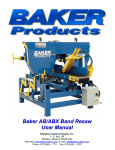
Baker AN-20 / AN-24 Planer
User Manual
Ellington Industrial Supply, Inc.
P. O. Box 128
Ellington, Missouri 63638 USA
Web site: www.baker-online.com E-mail: [email protected]
Phone: (573) 663 – 7711 Fax: (573) 663 – 2787
Baker AN-20 / AN-24 Planer - Rev 1, 06/07; WWW.BAKER-ONLINE.COM
1
Table of Contents
Warranty
Defective Parts
Service Policy
Rules for Safe Operation
Safety Expectations for Operating Power Equipment
Control of Hazardous Energy (Lockout / Tagout)
Planer Safety Instructions
Machine Specifications
Receiving
Installation
Dust and Chip Removal
Inspection
Before Operating
Lubrication
Planer Table
Table Rollers
Infeed Rollers
Out feed Roller
Chip Breaker
Pressure Bar
Test Cutting
Helical Cutter Head Knives
Parts List
Baker AN-20 / AN-24 Planer - Rev 1, 06/07; WWW.BAKER-ONLINE.COM
2
3
4
4
5
5
6
7-8
9
10
10
10
10
10
10
11
12
12
13
13
14
15
15
16-17
Warranty
Ellington Industrial Supply, Inc. machinery is warranted against defects in material or workmanship starting from the date
of shipment from the manufacturing plant.
This warranty is given solely to the “original purchaser” of the equipment and is in no way to be expressed or implied that
it is transferable to any other parties without the written consent and approval from the CEO or Sales Manager of Baker
Products.
Our one (1) year warranty period covers all items built at our manufacturing facilities including structural frame, cowlings,
doors, shafting, dust chutes and guards.
We honor six (6) months of warranty coverage for miscellaneous vendor-purchased-supplied items including bearings,
chain, sprockets, hydraulic components, etc.
Ninety (90) days of warranty coverage is provided on all electrical parts. All electrical components and wiring has been
installed in accordance with the National Electrical Code (NEC) of the United States of America.
Ellington Industrial Supply, Inc. does not warranty this machine to meet any other requirements or jurisdiction of any
electrical or safety codes of any other state, municipality, other country or jurisdiction The purchaser assumes all risk and
liability whatsoever resulting from the use thereof whether used singularly or in conjunction with other machinery or
apparatus, including, but not limited to, all matters resulting from sawdust generation.
Note: No warranty is provided on any electrical components or parts if equipment is powered or connected to a rotophase electrical converter in order to create a three phase power supply for operational current from a single phase
source.
Any change in materials, design, or performance intended to improve any product of Ellington Industrial Supply, Inc. shall
not obligate Ellington Industrial Supply, Inc. to modify any previously manufactured equipment.
This manual may contain details that if not properly followed can affect the performance of your equipment. You are
responsible for proper use and maintenance of your equipment and we reserve the right to deny warranty work if deemed
to be caused by a lack of proper maintenance or negligence by the owner or any of their employees.
Baker AN-20 / AN-24 Planer - Rev 1, 06/07; WWW.BAKER-ONLINE.COM
3
Defective Parts
Parts claimed defective must be returned freight prepaid, to our plant in Ellington, Missouri. Any part determined defective
due to faulty workmanship or materials will be replaced or repaired (at our option) free of charge, F.O.B. our plant. This
warranty does not cover expendable items (i.e. drive belts, band wheels, conveyor belting, blades, cutters, guides, etc.).
Except as expressly provided herein, this warranty is in lieu of all other warranties, expressed or implied, including a
warranty of merchantability or fitness for a particular purpose. This warranty is “void” if any part of the unit has been
tampered with, modified, altered, or operated with parts other than supplied or recommended by Ellington Industrial
Supply, Inc. In no event shall Ellington Industrial Supply, Inc. be liable for special, indirect, incidental or consequential
damages, however arising, including but not limited to, the loss of earnings or the cost of downtime.
Service Policy
In the event that you have any problems, call us at (573) 663-7711 any time between 8:00 AM and 5:00 PM (CST),
Monday through Friday. A member of our trained staff will answer any questions you may have. We charge nothing for
this service.
The only charge is for replacement parts not covered by warranty or after our inspection we deem that the problem is due
to operator error or lack of proper maintenance or neglect.
If it is necessary for a member of our service department to visit your plant at your request, there will be a charge for this
service. Call our service department for current prices.
Retain this Information for your Records
Model Number: ………………………………………...………………………….
Serial Number: …………………………………………………………………….
Date of Purchase: …………………………………………………………………
Power Source:…………..…………………….……………………………………
Dust Removal: ….……………………………………………………………….…
Baker AN-20 / AN-24 Planer - Rev 1, 06/07; WWW.BAKER-ONLINE.COM
4
Rules for Safe Operation
The purpose of safety symbols and signage is to draw your attention to real or possible hazardous conditions that may
exist when operating this equipment. Please remember that safety symbols and signage alone do not eliminate danger
and are not substitute for proper training and education regarding operational hazards.
This symbol and warning indicates a potentially hazardous
situation, which, if not avoided, will result in death or serious injury.
This symbol and warning indicates a potentially hazardous
situation, which, if not avoided, could result in death or serious
injury.
This symbol and warning indicates a potentially hazardous
situation, which, if not avoided, may result in minor or moderate
injury.
This warning provides notice and instruction regarding a potentially
hazardous situation, which, if not avoided will result in serious injury
or death.
SAFETY EXPECTATIONS FOR OPERATING POWER EQUIPMENT
ALWAYS…
•
•
•
•
•
•
•
•
•
•
•
•
ENSURE THAT TRAINED PERSONNEL OPERATE, MAINTAIN AND REPAIR THIS EQUIPMENT
TURN POWER OFF AND LOCKOUT / TAGOUT PRIOR TO PERFORMING MAINTENANCE
KEEP WORK AREA CLEAN AND WELL LIGHTED TO MINIMIZE OR ELIMINATE HAZARDS
KEEP CHILDREN AND VISITIORS AWAY FROM OPERATING EQUIPMENT
OPERATE THE EQUIPMENT AT THE RATE IT WAS DESIGNED FOR
KEEP GUARDS IN PLACE WHEN OPERATING EQUIPMENT
REMOVE TOOLS BEFORE RESUMING OPERATION
USE PROPER EXTENSION CORD
WEAR PROPER APPAREL AND AVOID LOOSE CLOTHING AND ACCESSORIES THAT COULD GET CAUGHT
IN MOVING PARTS
ALWAYS WEAR SAFETY GLASSES AND HEARING PROTECTION
AVOID “KICK-BACK” BY KNOWING WHAT CONDITIONS CAN CREATE IT
CHECK DAMAGED PARTS AND REPAIR OR REPLACE THEM IMMEDIATELY
NEVER…
•
•
•
LEAVE MACHINERY RUNNING OR UNATTENDED, ALWAYS TURN POWER OFF
OPERATE EQUIPMENT WHEN TIRED, FATIGUED OR UNDER THE INFLUENCE OF DRUGS OR ALCOHOL
ALLOW UNTRAINED PERSONNEL TO OPERATE, MAINTAIN OR REPAIR THIS EQUIPMENT
No list of safety expectations can ever be complete as every work environment is as different
as are the people operating the equipment.
Always keep safety as your highest priority and always use this machine with caution and
respect.
Baker AN-20 / AN-24 Planer - Rev 1, 06/07; WWW.BAKER-ONLINE.COM
5
Control of Hazardous Energy – (Lockout / Tagout)
Lockout / Tagout (LOTO) refers to specific practices and procedures to safeguard employees from the unexpected
energy, startup of machinery/equipment, or the release of hazardous energy during service or maintenance
activities.
This requires that a designated individual turn off and disconnect the machinery/equipment from its energy
source(s) before performing service or maintenance and that the authorized employee(s) lock and tag the energyisolating device(s) to prevent the release of hazardous energy and take steps to verify that the energy has been
isolated effectively.
List of Related Terms
Affected Employee
Authorized Employee
Energy Source
Lockout
Servicing and / or
Maintenance
Tagout
An employee whose job requires them to operate a machine or piece of equipment on
which service or maintenance is being performed.
A person who locks or implements a tagout system procedure on machines or
equipment to perform service or maintenance on that machine or equipment. An
authorized employee and an affected employee may be the same person when the
affected employee's duties also include performing service or maintenance.
Any source of electrical, mechanical, hydraulic, pneumatic, chemical, thermal, or other
energy.
The placement of a lockout device (such as a lock) on an energy-isolating device, in
accordance with an established procedure that ensures the device and the equipment
cannot be operated until the lockout device is removed.
Workplace activities such as constructing, installing, setting up, adjusting, inspecting,
modifying, maintaining or servicing machines or equipment. These activities include
lubrication, cleaning or un-jamming of machines or equipment, and making
adjustments or tool changes where the employee may be exposed to the unexpected
energy, start-up of equipment or release of hazardous energy.
The placement of a tagout device (such as a tag) on an energy-isolating device, in
accordance with an established procedure that ensures the device and the equipment
may not be operated until the tagout device is removed.
Example of lockout tags, lockout hasp
and keyed lock
1.
2.
3.
4.
5.
The Fatal Five Main Causes of
Lockout/Tagout Injuries
Failure to stop equipment
Failure to disconnect from a
power source
Failure to dissipate (bleed,
neutralize) residual energy
Accidental re-starting of
equipment
Failure to clear work areas before
re-starting
Baker AN-20 / AN-24 Planer - Rev 1, 02/07; WWW.BAKER-ONLINE.COM
6
Planer Safety Instructions
Read this instruction manual thoroughly before operating the machine. Be sure and understand the
limitation and dangers that may occur during the operation of the machine.
Only allow authorized persons who have been properly trained to operate the machine.
Insure that the machine is properly connected to the power supply.
NOTE: Only a licensed electrician should install this machine.
Before the power supply is connected, be sure that all switches are in the off position.
Disconnect the electrical power before installing knives, heads or performing routine maintenance on the
machine. Inspect the machine or change parts only when the machine is turned off.
Operate the machine only with all the safety guards and covers properly installed.
Be sure cutterhead rotates under power in a counterclockwise direction when viewed from the main drive
motor side.
Make all machine adjustments with power off, except for setting the feed speed rate.
Never leave the machine operating unattended. When shutting the machine down, remain near the machine
until all motion stops.
Keep the machine free from sawdust buildup - especially build up of sawdust around the motors.
Make certain that machine frame is electrically grounded and that a grounding lead is included in the
incoming electrical service. In cases where a cord and used, make certain that grounding lug connects to
a suitable ground.
Keep the floor around the machine clean and free of scrap material, sawdust, oil or grease to minimize
the danger of tripping or slipping. Ensure the table is free of all scrap, foreign material and tools before
starting a cut.
Before operating the machine, remove, tie, watch and other jewelry and roll up sleeves above the elbows.
Remove all loose clothing and confine long hair.
Always wear protective type footwear and hearing protection. Do not wear gloves.
Wear an approved safety shield, goggles, or glasses to protect eyes when operating the planer.
Keep hands outside the machine and never reach under the guards to try to clear stock that stops
feeding. Do not clear chips and sawdust with hand, use an air hose or hand brush.
Do not let on lookers come in contact with machine or incoming source power at any time.
Operator should stand to the side and out of line with the table during operation.
Baker AN-20 / AN-24 Planer - Rev 1, 02/07; WWW.BAKER-ONLINE.COM
7
Keep tools sharp and clean for safest and best performance. Dull tools increase noise level and can
cause kickbacks. A cutterhead that is not securely locked in place can be thrown out of the planer
causing severe or fatal injury as well as damage to the machine. Do not use knives that have been
reground to less 3/4”(19mm) height on standard cutterhead.
Do not make any cuts requiring more power than available on the machine.
Do not attempt to feed two boards side by side on any machine not equipped with a sectionalized infeed
roller and chip breaker.
Do not planer boards with loose knots or with nails or any foreign material on the surface. Knife impact on
these objects can cause the knives to be pulled out and cause them to shatter against the chip breaker or
pressure bar.
Do not feed stacked board through a planer as kickback can occur causing sever or fatal injury.
Do not attempt to plane boards shorter than 10” (250mm) in length without butting aboard of equal
thickness behind it to help it through the planer. Be sure the last board of a butted sequence is 10”
(250mm) long or longer.
If the board being planed stops feeding, disengage or turn the feed off and turn the power off. Wait until
the cutterhead comes to a complete stop before lowering the table to remove the board. Never lower the
table with the power on and the stock still in the machine. A kickback can occur which could cause a
severe or fatal injury.
Avoid accidental starting by ensuring switch is turned off when connecting power to the machine.
If the operator needs to leave the work area for any reason, the planer should be turned “off” and the
cutterhead should come to a complete stop prior to leaving.
Baker AN-20 / AN-24 Planer - Rev 1, 02/07; WWW.BAKER-ONLINE.COM
8
Machine Specifications
Subject
Model AN-20
Model AN-24
21” x 27.5” (54.6cm x 70cm)
25.4” x 28” (64.6cm x 71cm)
2.99” (76mm)
2.99” (76mm)
5200 rpm
5200 rpm
2.75” (70mm)
2.75” (70mm)
Outfeed roller diameter
52mm
52mm
Bed roller diameter
55mm
55mm
315” / min (8m / min)
315” / min (8m / mi)
3/8” (10mm)
3/8” (10mm)
1/8” – 6-3/4” (3 - 170mm)
1/8” – 6-3/4” (3 - 170mm)
Widest planeable butted stock
20” (508mm)
24” (610mm)
Shortest planeable stock not butted
6” (150mm)
6” (150mm)
5hp
7.5hp
728 lbs (330 kgs)
793 lbs (360 kgs)
Table area
Cutterhead diameter
Max. cutterhead R.P.M.
Infeed roller diameter
Feed speed
Max depth of cut single board
Stock range thickness
Motor
Approximate weight
NOTE: Do not equip your planer with a motor of higher horsepower than it is specified, nor
run the cutterhead in excess of the maximum rpm specified.
Scale
On / Off switch
Table
Hand wheel
Table roller height adjustment
Pictured is a Model AN-24
Baker AN-20 / AN-24 Planer - Rev 1, 02/07; WWW.BAKER-ONLINE.COM
9
Receiving
Uncrate machine and check for shipping damage. Report any damage to the carrier and your distributor
immediately. If accessories were ordered with the machine, these will be in a separate container and should be
checked for completeness and damage. Notify the carrier and your distributor immediately if any items are
missing or damaged. Clean protective coating from all areas and lubricate parts as indicated in this manual.
Installation
Mount machine on a solid foundation, preferably a concrete floor, and lag machine to the floor through the holes
provided in the base. The machine area should be clean, dry well ventilated, and well lighted. Since planer can
create noise problems, the site selection should be one, which minimizes reverberant sound from walls, ceilings
and other equipment. Electrical should be installed so that they are protected from damage and exposure. Be
sure to properly ground the machine frame.
Dust and Chip Removal
Utilize a dust collection system of sufficient size that is rated at a minimum of 1,500 cfm.
Inspection
Before putting power on the machine, check that all screws are tight, that all mechanical functions work freely and
that the cutter head turns freely without knife contact with the chip breaker or pressure bar. Periodic or regular
inspections are required to insure that the machine is in proper adjustment, that all screws are tight, that belts are
in good condition, that dust has not accumulated in the electrical enclosures and that there are no loose or worn
electrical connections.
Before Operating
Check the motor and switch-wiring diagram for proper voltage connection before applying power to the machine.
Turn the main drive motor on momentarily to check for proper direction of rotation. Correct as required. Cutter
head should rotate counterclockwise when viewed from the sheave or motor side. The infeed roller should turn
clockwise when from the motor side planer. Run the machine without cutting for a short period of time to check
that all power function are operating properly. Be sure to read and understand the operating instruction manual
using the planer.
Lubrication
The table roller, infeed roller and outfeed roller are mounted on sealed ball bearing and require no lubrication. The
following table indicates the lubrication points, frequency, and recommended lubricant.
Point
Cutter head housing
Table raise/lower slides
Table elevating ball screws
Forward drive gears
Frequency
Daily
Weekly
Weekly
Weekly
Lubricant
High speed grease
SAE 10
SAE 10
SAE 10
Baker AN-20 / AN-24 Planer - Rev 1, 02/07; WWW.BAKER-ONLINE.COM
10
Planer Table
The planer table is raised and lowered by three screws supported on thrust bearing and is guided by machine surface
on the side panels. The fit-up to prevent the table from rocking is controlled by two gibs in front. These gibs should be
adjusted individually using the gib bolts provided, so that there is light contact on all four surfaces. The gibs should be
tight enough to prevent rocking or movement of the table when planer is in operation.
To do accurate planning, the table must be parallel with the cutter head. Lack of parallelism results a taper over the
width of the board. Check with straddle-type knife gauge to insure knives have the same protrusion from the cutter
head arc end to end that each knife is the same. Maximum deviation allowed for good planning is 0.02mm.
Place a 5” x 5” (125mm x 125mm) gauge block to be used as a feeler gauge at the extreme right hand side of the table,
rotating the head so the knives clear the gauge surface.
Raise the table with the table raising hand wheel until the block just touches the cutter head. Move the block to the
extreme left side of the table. Using the block, find the low point of the cutter head without moving the table height.
Note whether the reading is less than or greater than left side, if greater on the left side, the left side of the table must
be lower; if less, the left side of table must be raised. With the gauge block under left side that must be raised or lower,
loosen the lock screw locking the threaded flange nut from rotation in the table on the side to be raised or lowered
lower.
Rotate the nut using a rod in the flange holes and adjust height of the left side. Relock the flange nut lock screw in the
table.
Table
Gib
Gib Screws
Gib
Gib Screws
Baker AN-20 / AN-24 Planer - Rev 1, 02/07; WWW.BAKER-ONLINE.COM
11
Table Rollers
Two table rollers are utilized to help reduce friction of the stock on the table as it feeds through the planer.
Zero the indicator to the table, then place a gauge over the extreme right side of table roller and find the high point of
the roller arc. The standard setting is 0.5mm. If the reading is greater or less than this reading, loosen the nut, and
adjust the hex head jackscrew to position the roller to the desired 0.5mm setting. Repeat the process on the left side
and then recheck the right side. Relock the nuts when finished adjusting.
Table Roller
Set Screws
(one per side)
Bottom-side
of Table Roller
Infeed Rollers
The function of the infeed roller is to feed the material into the machine. It is a corrugated roller and when sectionalized
is made up of one inch wide sections with 1/4” (6mm) movement in each section to accommodate multiple board
surfacing. In addition, the whole assembly is rubber loaded to accommodate the full 1/4” (6mm) depth of cut. To provide
proper drive, it should be set so that the bottom of its arc is 1.6mm below the arc of the cutter head knives.
Using a gauge block or a short piece of finished lumber notched to clear the table roller, place the gauge under the
cutter head and raise the table with the table raising hand wheel. Next, rock the cutter head back and forth until it just
touches the gauge/material being used. If it will not go in, the roller must be raised. If clearing, it must be lowered.
Unlock the setscrew and adjust as required so that the roller just touches. Move the gauge block to the extreme left
side and adjust that side as required until the roller just touches the gauge. Recheck the right side and then lock the
setscrew with the jam nuts provided.
Helical
Cutter head
Infeed Roller
Infeed Roller
adjustment bolt
(one per side)
Baker AN-20 / AN-24 Planer - Rev 1, 02/07; WWW.BAKER-ONLINE.COM
12
Outfeed Roller
The outfeed roller is smooth and of one-piece construction to help avoid marring the finished surface of the material
being cut. Its function is to continue to feed the material through the machine after it leaves the infeed roller. The correct
free position setting is .8mm below the arc of the cutter head knives. Adjust the outfeed roller using the same procedure
as used for the infeed roller.
Chip Breaker
The function of the chip breaker is to help avoid splintering out of the wood, to break chip into small pieces, to help
avoid board bounce on thinner boards, to direct the flow of chip out of the machine, and to permit multiple board
surfacing up to 6mm difference in thickness.
The chip breaker in its free position should be set the same height as the infeed roller. Using the same method as
indicated for the infeed roller, adjust the chip breaker free position using a gauge block or short piece of finished lumber
to check for proper thickness at each end. It is important that each end be close to the same height to help avoid
skewing of the material as it is fed through the machine. Since the chip breaker adjusting screws contact the bearing
house for the infeed roller, its adjustment should be made after the infeed roller and if the infeed roller setting is altered,
the chip breaker must be readjusted.
NOTE: A chip breaker set too low may prevent stock from feeding into the machine.
View of Chip
Breaker with
top cover open
Baker AN-20 / AN-24 Planer - Rev 1, 02/07; WWW.BAKER-ONLINE.COM
13
Pressure Bar
Most planing problems can be related to improper setting of the pressure bar. Its function is to hold the material down
after it passes under the cutter head and throughout the remainder of the cut. Its basic setting is to be in line with the
arc of the cutter head knives. If it is too high, a shallow clip will occur in from each end of the board. If it is too low, stock
will not feed through.
Using a gauge block, raise the table with its elevating hand wheel to determine the low point of the arc of the cutter
head. Move the gauge block under the low point of the extreme right hand side of the table and adjust that end of the
pressure bar with the jackscrews provided to be line with the low point of the knife arc. Recheck the right side and then
check the full width of the pressure bar. If the center is slightly low, adjust both sides the same amount to bring the low
point into line. Using the gauge block, set the full length of the pressure bar to be 0.02mm above the arc of the cutter
head. This initial setup is starting point and final adjustment may have to be made during a test cut.
Dust removal
cover open
Pressure bar sits
directly behind
cutter head
Pressure Bar
adjustment
screw
Cross section drawing of
Planer components
Baker AN-20 / AN-24 Planer - Rev 1, 02/07; WWW.BAKER-ONLINE.COM
14
Test Cutting
Using a piece of semi-finished stock, set up for a 1.5mm deep cut with the quick-set adjustment at zero. Start the
machine, stand to the left or right hand side and begin feeding the stock into the machine.
Note: Never stand directly behind the infeed to see how the stock is feeding. A kick-back could occur resulting
in serious or fatal injury.
The infeed roller should take the material and force it under the chip breaker and cutter head. If the material feeds
through effortlessly, examine the finished cut carefully for imperfection. Learning to read a board for imperfections will
save hours in adjusting your planer to operate properly.
Helical Cutter Head Knives
Both the AN-20 and AN-24 feature helical cutter heads that reduce maintenance down time and provide an extended
cutting life beyond the traditional straight knife cutters. The helical cutter heads have six (6) slots or rows of four-sided,
self-seating cutter knives that are simple to rotate and change.
Four-sided selfseating knifes have
mark for consistent
positioning and
rotation
Helical cutter has (6) slots or
rows of cutter knives
Baker AN-20 / AN-24 Planer - Rev 1, 02/07; WWW.BAKER-ONLINE.COM
15
Parts List
ITEM
DESCRIITION
QTY
30
Table roller
2
60
Nut ,infeed roller L.H.
1
1
1
L.H. Panel
1
31
Table roller bar
4
61
Infeed roller shaft
2
Hex hd. Cap.5/16”*1”
3
32
Hex hd. Cap 3/8”*1”1/2
4
62
Infeed roller
20/24
3
Washer lock 5/16”
3
33
Thrust bearing plate
4
63
Rubber grain
80/96
4
Plate, table rising shaft L.H.
1
34
Hex hd. Cap 5/16”*3/4”
2
64
Nut, infeed roller R.H.
1
5
Shaft Ring,
1
35
Thrust bearing 2904
2
65
Housing, infeed roller R.H.
1
6
Bevel gear (short)14t
2
36
Table raising screw L.H
2
66
Housing cover L.H.
2
7
Shaft counter 3/4”
1
37
Nut table raising L.H.
1
67
Gear ring,
2
8
Base planer
1
38
Hex hd cap. 3/8”*1”
4
68
Helical gear, 38T, infeed roller
1
9
Bevel gear 24t
3
39
Hex hd cap. 3/8”*1”1/4
1
69
Gear Key , 1/4”*1/4”*L22
2
10
Bracket, rising shaft
1
40
Lock set nut
1
70
Bearing nut ¢25
2
11
Hex hd. Cap.5/16”*1”1/2
3
41
Screw, able raising R.H.
1
71
Pulley, cutter head L.H.
1
12
Hex hd. Cap.5/16”*3/4
3
42
Washer 3/8”
1
72
Housing cover, ¢62
1
13
Bevel gear(long) 14t
1
43
Nut, Table raising R.H.
1
73
Bearing, 6206
2
14
Hand wheel shaft Ring, t
1
44
Gib, table
2
74
Housing, cutter head L.H.
1
15
Hand wheel Shaft, l 7/8”
1
45
Table
1
75
Pressure bar hanger
2
16
Hex hd cap 3/8”*1” & washer
lock
2
46
Hex hd cap. 5/16*1”1/2
6
76
Cutter head
1
17
Hanger, hand wheel shaft
1
47
Helical gear 26T out feed roller
1
77
Housing, cutter head R.H.
1
18
Hand wheel 9” dial
1
48
Hex hd cap. 7/16’*1”1/4
8
78
Hanger, feed drive gear
1
19
Handle nylon 3/8”
1
49
Panel scale depth 8”
1
79
Helical gear, feed drive 26t
1
20
Feed drive panel
1
50
Pointer table height
1
80
Bearing, 6007Z
1
21
Hex hd. Cap. 3/8”*2”1/2
4
51
Housing cover ¢52 R.H.
2
81
R-62
1
22
Panel side R.H.
1
52
Ring S-25
2
82
Bearing nut, ¢35
1
23
Side shaft 3/4”, rear
1
53
Bearing 6205
4
83
Pulley, cutter head R.H.
1
24
Side shaft 5/8” front
1
54
Hex hd cap. 3/8”*1”1/2
2
84
V-belt, A-56
1
25
Hex hd. Cap.5/16”*1”1/4
1
55
Housing, infeed roller LH.
1
85
Sq hd scr 5/16”*3/8”
26
Panel side L.H.
1
56
Nut 3/8”
4
86
Knife gib,
3
27
Bearing 6304Z
4
57
Spring, infeed roller
2
87
Knife 30*3*508/610
3
28
Table roller shaft
2
58
Washer 3/8”
4
88
Knife spring
6
29
Set screw, hand wheel shaft
1
59
Hex head screw 3/8” x 5”
2
89
Spring pressure bar R.H.
1
Baker AN-20 / AN-24 Planer - Rev 1, 02/07; WWW.BAKER-ONLINE.COM
16
36/30
90 Pressure bar
1
118
Spring, chip breaker
compression
20/24
91 Spring, pressure bar L.H.
1
119 Hand shaft, chip breaker
1
92 Housing, out feed roller L.H.
1
120 Upper roller
2
93 Spring, out feed roller
2
121 Bracket, chip breaker R.H.
1
94 Hex hd scr 3/8”*3”1/2
2
122 Hex hd scr 3/8”*1”
4
95 Hex hd scr 3/8”*1”1/2
2
123 Nut,, 1/2”
6
96 Out feed roller
1
124 Jaw, chip breaker R.H.
1
97 Housing, out feed roller R.H.
1
Hex hd scr 3/8”*1” & lock
125
washer
4
98 Feed drive base
1
126 Chip breaker shaft, front 3/4”
1
99 Bearing, 6202Z
2
127 Chip breaker shaft, rear 3/4”
1
100 Helical gear 13t
1
128 Hex hd scr 3/8”*2”
2
101 Gear, 80t
1
129 Front panel
1
102 Bearing, 6201Z
2
130 Hex hd scr 5/16”*1/2”
2
103 Nut, 1/2”
2
131 Motor bracket, J from
1
Hex hd scr 3/8”*1”& wash
104
lock
2
132 Motor bracket, L from
1
105 Pulley, B type
1
133 Motor support
1
106 V-belt, B-37
1
134 Set scr 5/16”*1/2”
1
107 Gear, 20t
1
135 Motor pulley
1
108 Nut, 5/8”
1
136 Motor key
1
109 Bearing, 6203Z
1
137 Motor
1
110 Nut, 3/4”
1
138 Motor V-belt, A-53/A-54/A-55
2
111 Washer, 3/4”
1
112 Pulley shaft
1
113 Bearing, 6204Z
1
114 Multi-pulley
1
115 Jaw, Chip breaker L.H.
1
116 Bracket, chip breaker L.H.
1
117 chip breaker
20/24
Baker AN-20 / AN-24 Planer - Rev 1, 02/07; WWW.BAKER-ONLINE.COM
17