1
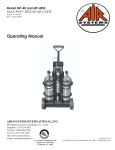
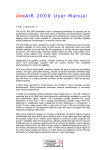
Frontier
Self Contained Breathing Apparatus
User
s Manual
Users
User's Manual
for the
FR
ONTIER
FRONTIER
Self Cont
ained Breathing Apparatus
Contained
MODELS
Frontier, 2216 psi, 30 minute
NIOSH approval TC-13F-491
Frontier, 4500 psi, 30 minute
NIOSH approval TC-13F-492
Frontier, 4500 psi, 45 minute
NIOSH approval TC-13F-493
Frontier, 4500 psi, 60 minute
NIOSH approval TC-13F-494
WARNING
Disassembly of the components beyond the procedures described herein shall
not be performed. Additional disassembly may cause component damage and
shall only be performed by authorized personnel or the factory.
INTEC Controls, Inc.
9730 Distribution Ave.
San Diego, CA 92121
ph: (858) 578-7887
fx: (858) 578-4633
www.inteccontrols.com
[email protected]
Part Number: 084062
Artwork Number: A49095
Issue B
Issue B
August 22, 2002
August 22, 2002
TABLE OF CONTENTS
PREFACE-IMPORTANT POINTS
Intent
Training
NIOSH Warnings
Cautions & Limitations
Special or Critical User Instructions
1.0
1
1
1
1
2
2
DESCRIPTION OF FRONTIER
2
1.1
1.2
1.3
1.4
1.5
1.6
1.7
2
3
3
3
3
3
4
6.0
7.0
8.0
2.0
3.0
4.0
5.0
Facemask or Hood
Compact Demand Valve
First Stage Pressure Reducer
End-of-service Alarms
Backframe and Harness
Cylinder and Valve Assembly
Frontier Cylinder Table
ROUTINE CHECKS
4
2.1
2.2
2.3
Unpacking
Inventory and Examination
Routine Checks and Inspections
4
4
4
DONNING PROCEDURES AND SAFETY
CHECKS
6
3.1
3.2
6
7
Donning Procedures
Safety Checks
DURING USE
8
4.1
4.2
8
9
Normal Use
Emergency Egress Indicators
AFTER USE PROCEDURES
9
5.1
9
Doffing
9.0
10.0
AFTER USE CLEANING
9
6.1
6.2
9
10
Clean Facemask
Cleaning SCBA
SCBA STORAGE
10
7.1
SCBA Storage
10
USER MAINTENANCE
10
8.1
8.2
8.3
8.4
10
11
12
13
Cylinder Filling Procedures
Facemask Disassembly & Reassembly
Facemask Harness Replacement
Backframe Harness
FRONTIER OPTIONS
13
9.1
9.2
13
14
Airline
Buddy Breather
TROUBLESHOOTING GUIDE
15
PREFACE
IMPORTANT POINTS - PLEASE READ CAREFULLY
FAILURE TO PROPERLY USE AND MAINTAIN THIS
PRODUCT COULD RESULT IN INJURY OR DEATH
INTENT
This manual is intended to acquaint owners and users with
operation for the FRONTIER Self-Contained Breathing Apparatus and to provide important safety information and limitations.
All information, illustrations and specifications in this manual are
based on the latest product information available at the time of
printing. The right is reserved to make changes at any time
without notice.
IMPORTANT
ALL PERSONNEL USING THIS APPARATUS SHALL BE
THOROUGHLY TRAINED BY A QUALIFIED INSTRUCTOR
IN DONNING, OPERATION, INSPECTION AND EMERGENCY OPERATION.
EQUIPMENT SHOULD BE THOROUGHLY CHECKED AND
CLEANED AFTER EXPOSURE TO INTENSE HEAT OR
HARSH CHEMICALS.
The FRONTIER pneumatics are designed to be simple to use
and easy to maintain and will operate for many years if properly
maintained and cleaned. The instructions for care and use
given in this manual must be read, understood and carefully
followed before the apparatus is used.
The procedures in this manual DO NOT render us liable for any
losses or injury arising from any actions based on use of same.
Spare parts and accessories are available through your local
authorized distributor. Suggested spare parts from other
sources will void NIOSH approvals. Service beyond the
scope of this manual is not recommended. If a problem persists, the apparatus should be removed from service, tagged
for repair and forwarded to an authorized distributor or to
the factory for evaluation and/or repair.
TRAINING
We strongly recommends that the training program be consistent with Occupational Safety and Health Programs. Training
and servicing programs are available upon request. Please
contact your local distributor for further details.
NIOSH/OSHA WARNINGS
The following warnings are given in accordance with accepted
safety conventions and/or NIOSH/OSHA requirements, and
apply to the use of breathing apparatus in general.
HEALTH LIMITATIONS: Wearers of SCBA should be certified
medically fit prior to use. In addition, there are both physiological
and psychological limitations which should be considered before using SCBA. They include, but are not limited to:
*
*
*
*
*
*
*
*
*
*
*
*
*
*
Emphysema
Chronic obstructive pulmonary disease
Bronchial asthma
X-ray evidence of pneumonia
Evidence of reduced pulmonary function
Coronary artery disease
Severe or progressive hypertension
Epilepsy (grand mal or petit mal)
Pernicious anemia
Diabetes (insipidous or mellitus)
Breathing difficulties when wearing an SCBA
Claustrophobia or anxiety when wearing an SCBA
Abnormal EKG results from resting or stress tests
Punctured or ruptured ear drum
WORKING TEMPERATURES: FRONTIER is approved for
respiratory protection during entry into or escape from oxygen
deficient atmospheres, gases, and vapors at temperatures
above -25°F. When used below freezing, care must be exercised to prevent moisture from entering the demand and exhalation valves. This includes when cylinders are being changed.
DURATION OF USE: Although the FRONTIER has been
approved as either a 30-minute, 45-minute, or 60-minute breathing apparatus, the wearer’s varying work rate, physical condition and other factors could substantially shorten the actual
usable duration of the unit.
SCBA LIMITATIONS: SCBA can only protect the wearer’s
respiratory system. Other protection may be necessary to avoid
contamination through skin absorption. If these types of materials are suspected, an effective full-body covering of impermeable material must be worn with the SCBA. A universal Class A
HazMat suit pass through is available for the FRONTIER from
us or HazMat suit manufacturers.
FACIAL HAIR: Facial hair or any items which may interfere with
the seal surface, or in the operation of the exhalation valve, must
not be allowed. These include beards, sideburns, mustaches,
bangs, head coverings, or anything that may interfere with the
correct seal of the facemask to the face. An optional hood is also
available for those with facial hair.
EYE WEAR: Eye glasses shall not be used when the temple
bars interfere with the proper seal of the facemask to the face.
If a user must wear corrective lenses while wearing the SCBA,
they can be mounted in the facemask using a special lens
mounting kit available from us or through your local distributor
An optional hood is also available that allows the user to wear
glasses with temple bars.
MANUAL BYPASS: The FRONTIER has a manually operated
bypass which provides a continuous flow of air to the facemask
when required, independent of normal operation of the regulator. The bypass is opened by turning the red knob on the
Compact Demand Valve 90 degrees.
1
CAUTIONS AND LIMITATIONS
SPECIAL OR CRITICAL USER’S INSTRUCTIONS
•
Airline respirators can be used only when the respirators are
supplied with respirable air meeting the requirements of CGA G7.1 Grade D or higher quality. Use only the pressure ranges and
hose lengths specified in the User’s Instructions.
•
Approved for respiratory protection during entry into or escape
from oxygen deficient atmospheres, gases and vapors at
temperatures above -25°F.
•
•
Failure to properly use and maintain this product could result in
injury or death.
•
All approved respirators shall be selected, fitted, used, and
maintained in accordance with OSHA and other applicable
regulations.
Approved only when compressed gas container is charged with
air meeting the requirements of CGA G-7.1 Grade D or higher
quality that has a dew point of -65°F or lower and a maximum
particulate level of 5 mg/m3 air.
•
The compressed gas container shall meet applicable DOT
specifications.
•
When used as a combination apparatus, only 20% of the service
pressure may be used on entry.
•
This approval applies only when the device is supplied with
respirable breathing air through 6 to 300 feet of hose at air
pressures between 80 to 120 pounds per square inch gauge or
from self contained air supply.
•
If the supplied air fails, open the cylinder valve and proceed to
fresh air immediately.
•
Use adequate skin protection when worn in gases and vapors
that poison by absorption (example: hydrocyanic-acid gas).
•
Never substitute, modify, add, or omit parts. Use only exact
replacement parts in the configuration as specified by the
manufacturer. Do not mark the unit with inks or paints which
might be flammable; vibratory etching may be used on all parts
except the visor and cylinder.
•
Refer to User’s Instructions and/or maintenance manuals for
information on use and maintenance of these respirators.
•
Special or critical User’s Instructions and/or specific use
limitations apply. Refer to User’s Instructions before donning.
1.0 DESCRIPTION OF FRONTIER SCBA
FACEMASK
1.1
HOOD
FACEMASK OR HOOD
The full facemask assembly has a four-point adjustable
head harness. The interior of the visor can be purchased with
an optional permanent anti-fog coating. The facemask standard seal has a blended shape to ensure a proper fit. A standard inner-mask nosecup reduces dead-air space and CO2
buildup.
The FRONTIER is a self-contained, open-circuit, compressed-air breathing apparatus that is approved by the National Institute of Occupational Safety and Health (NIOSH).
Positive pressure is maintained within the facemask during
use, thus providing the highest degree of respiratory protection in irrespirable atmospheres by preventing any inward
leakage.
The FRONTIER consists of several major components described in the following paragraphs:
2
The Hood is also available for users that prefer to wear
their own eyeglasses or may have facial hair that may interfere
with the sealing surface. The sealing surface of the hood is
around the neck. The sealing surface must not have any hair
interfering with the neck seal. The Hood is NIOSH
approved for entry into an IDLH atmosphere. The Hood has a
hard visor with a permanent anti-fog coating that offers
excellent vision, an inner nosecup to reduce CO2 build-up, and
adjustable side straps for a comfortable fit. The Hood is
available in two sizes to comfortably fit any person.
1.5
1.2
BACKFRAME AND HARNESS
COMPACT DEMAND VALVE (CDV)
The patented Compact Demand Valve regulator combines
high flow with a low profile to improve mobility. The CDV exhalation valve greatly reduces breathing resistance which allows for longer duration of cylinder use. The CDV is easily
docked into the facemask using a threaded handwheel.
The backframe and harness assembly utilize ergonomic design principles to produce a comfortable, low profile unit that
evenly distributes the SCBA weight between the wearer’s
hips and shoulders.
A quick-release cylinder band fits a wide range of cylinders
with an infinitely adjustable strap to ensure a tight fitting cylinder.
The harness material is a custom woven Nylon with easy
slide shoulder buckles allowing for quick donning of the Frontier SCBA. Also available are the optional Kevlar straps and
shoulder pads.
1.6
1.3
FIRST STAGE PRESSURE REDUCER
Air leaves the cylinder, passes through a sintered bronze filter
in the handwheel assembly, and then continues on to the
first-stage pressure reducer where it is reduced to approximately 125 psi. The reducer is a simple piston type that requires no adjustment and incorporates an automatic, selfseating pressure relief valve to protect the downstream lowpressure components. It is made of high quality aluminum,
and is securely mounted to the cylinder.
REMOTE CYLINDER PRESSURE AND ENDOF-SERVICE TIME INDICATORS
1.4
The remote pressure gauge and whistle assembly is chest
mounted on the right shoulder strap. The pressure gauge is
waterproof with a neoprene protective cover and features a
luminous dial and pointer markings. The gauge display
shows the fraction of cylinder pressure remaining.
CYLINDER AND VALVE ASSEMBLY
A range of cylinder types and capacities are accommodated
on the FRONTIER 2216 psi and 4500 psi models. (Please
see the table in Section 1.7 for specifics.)
The cylinder valve is of forged aluminum construction with a
permanent teflon coating. The valve outlet is a standard
CGA-346 fitting on 2216 psi cylinders, and a standard CGA347 fitting on 4500 psi cylinders. Each valve has a frangible
disc safety relief device, and a dual-reading pressure gauge.
Valve protection is provided by an elastomeric bumper.
HANDLING PRECAUTIONS:
NEVER LIFT OR CARRY UNIT BY THE FACEMASK HOSE
OR GAUGE ASSEMBLY. IF A HOSE BECOMES KINKED
OR OTHERWISE DAMAGED, IT SHOULD BE REPLACED.
CHECK FOR DAMAGE NEXT TO THE METAL ENDS OF
THE HOSE.
The primary End-of-Service-Time indicator is a whistle which
is set to sound at 23%-27% of rated cylinder pressure per
NIOSH requirements.
3
1.7
FRONTIER CYLINDER TABLE
Part
Number
Pressure
PSIG
Material
Free Air
Capacity
NIOSH
Rated
Duration
@ 40 lpm
Cylinder
& Valve
Charged
Weight
Cylinder
Diameter
Hydrostatic
Interval
024.037.00
2216
Aluminum
1287 liters
45 cu. ft.
30 min.
20.5 lbs.
6.9 in.
5 years
024.035.00
2216
Hoop-Wrapped
Aluminum
1301 liters
45.5 cu. ft.
30 min.
16.0 lbs.
6.9 in.
3 years
124001
2216
Full Wrapped
Carbon
1301 liters
45 cu. ft.
30 min.
10.4 lbs.
6.8 in.
5 years
024.098.00
4500
Hoop-Wrapped
Aluminum
1287 liters
45 cu. ft.
30 min.
15.9 lbs.
5.5 in.
3 years
124002
4500
Full Wrapped
Carbon
1287 liters
45 cu. ft.
30 min.
11.0 lbs.
5.4 in.
5 years
124003
4500
Full Wrapped
Carbon
1887 liters
66 cu. ft.
45 min.
14.8 lbs.
6.8 in.
5 years
124004
4500
Full Wrapped
Carbon
2516 liters
88 cu. ft.
60 min.
19.2 lbs.
7.1 in.
5 years
2.0 ROUTINE CHECKS
2.1
UNPACKING
Open the storage case or shipping container. Observe the
relative position and placement of the various components for
future re-packing. Remove SCBA from container and place
on clean dry surface. Remove facemask from protective bag.
2.2
INVENTORY AND EXAMINATION
Examine unit for physical condition and appearance of all
components. Be sure the following major components are included:
•
•
•
•
2.3
Facemask or Hood
Backframe and Harness Assembly
Cylinder and Valve Assembly
Options ordered with unit
ROUTINE CHECKS AND INSPECTIONS
The following procedure shall be used for incoming and daily
inspection of the apparatus. An SCBA not routinely used, but
kept for emergency use, shall be inspected at least monthly.
All other apparatus shall additionally be inspected after each
use.
4
WARNING
THE APPARATUS MUST NOT BE USED UNTIL THE FOLLOWING TESTS HAVE BEEN SUCCESSFULLY COMPLETED. ANY DISCREPANCY NOTED DURING THE PRE-USE
CHECK AND INSPECTION SHALL BE CORRECTED ONLY
BY AUTHORIZED PERSONNEL PRIOR TO USE OF THE
APPARATUS.
2.3.1
Visually inspect complete apparatus for worn or
aged parts and damaged components.
2.3.2
Basic cylinder inspection shall include:
A. Inspect gauge for damage.
B. Inspect cylinder for mechanical damage (cracks,
dents, gouges) or signs of heat or chemical
damage. (Refer to CGA C-6.2 "Guideline for Visual
Inspection and Requalification of Fiber Reinforced
High Pressure Cylinders" for all wrapped cylinders.)
C. Check that hydrostatic test date on cylinder is
current.
D. Check that cylinder valve threads are not damaged.
E. Check that the valve body is not bent.
F. Check that the burst disc outlet is clean and free of
debris.
G. If any item listed above is noted, depressurize
cylinder to a slight positive pressure, tag, and take
out of service.
2.3.3
Connect the CDV to the FRONTIER facemask or
hood by screwing the CDV handwheel into the hood
or facemask. Make sure the manual red bypass knob
is in the closed position, i.e., fully turned clockwise.
2.3.4
Open the cylinder valve slowly by turning the cylinder valve knob counter-clockwise to the fully open
position. Hold facemask tight to your face. The
whistle alarm should activate and then shut off.
There should be no air flow from the facemask. If air
is flowing, check that bypass is closed.
2.3.7
To test the Hood for positive pressure, Insert two
fingers between the seal and neck. Gently lift the seal
away from the neck while pulling the nosecup away
from the face. A good outward flow of air should be
felt. Reseal the hood and stop breathing for three
seconds. There should be no sound of air leaking
from the CDV. Open the bypass knob and check for a
constant flow. Close the bypass knob.
2.3.8
Low Pressure Alarm Test: Close cylinder valve and
gradually reduce the pneumatics by opening the bypass to slowly vent the air. Check to see that the
whistle "End-of-Service" alarm activates as the
needle enters the red section of the gauge (1/4
marking).
2.3.9
Unscrew the CDV from the facemask or hood from
the SCBA by turning counterclockwise and pulling
the CDV out of the facemask.
2.3.10
Leak Test of SCBA: With the CDV disconnected
from the facemask or hood, open the cylinder valve
and place the test cap over the CDV outlet port. Do
not seal with test cap until air flow has begun. Allow
the pneumatics to pressurize and then close cylinder
valve. Lightly place a finger over the hole in the test
cap to restrict air flow. The needle on the pressure
gauge should not fall more than 1/8 inch per minute.
Remove the test cap to drain pneumatics.
Note:
The CDV flows a very small amount of air past the
pilot jet. The test cap has a small hole to allow the
air to escape. It may be necessary to hold the test
cap in place while performing the leak test.
2.3.11
Connect CDV to the facemask or hood. Pull gently
outward on the CDV to ensure it is docked properly.
2.3.12
Return apparatus to storage, or proceed to donning
instructions.
WARNING
ENSURE THAT ONLY A 2216 PSI CYLINDER IS USED
WITH LOW PRESSURE PNEUMATICS AND A 4500 PSI
CYLINDER IS USED WITH HIGH PRESSURE PNEUMATICS.
2.3.5
2.3.6
CHECK CYLINDER PRESSURE Remote cylinder
pressure gauge should read above 7/8 of maximum
rated pressure. If cylinder pressure reads 7/8 or
less, refill or replace with a fully charged cylinder.
While holding the facemask tight to your face, insert
two fingers between the facemask and face. Gently
lift the seal away from the face and ensure a good
outward flow of air. Reseal the facemask and stop
breathing for three seconds. There should be no
sound of air flowing. Open the optional bypass knob
and check for a constant air flow. Close bypass
knob.
IMPORTANT
COMPLETE ALL ROUTINE CHECKS AND INSPECTION
PROCEDURES OUTLINED IN SECTION 2 BEFORE STARTING DONNING PROCEDURES, SECTION 3.
WARNING
IF ANY OF THE ABOVE TESTS FAIL, REMOVE APPARATUS FROM SERVICE, TAG, AND RETURN FOR REPAIR
BY AUTHORIZED PERSONNEL.
TECHNICIAN MAINTENANCE
5
3.0 DONNING PROCEDURES AND SAFETY CHECKS
AFTER EVERY 100 HOURS OF USE, OR AT LEAST ONCE
PER YEAR, THE ENTIRE SCBA SHOULD BE PLACED
OUT OF SERVICE AND TAGGED FOR COMPREHENSIVE
MAINTENANCE BY AUTHORIZED TRAINED TECHNICIAN.
3.1
DONNING PROCEDURES
3.1.1
Position the FRONTIER on the ground with the cylinder valve facing towards the wearer.
3.1.2
3.1.3
6
3.1.4
Pull directly down on the shoulder straps to adjust
position of unit on back.
3.1.5
Connect the waistbelt buckle and adjust waistbelt to
a comfortable snug fit. Tuck the excess waistbelt
and shoulder strap pull-downs inside the waistbelt.
3.1.6
Donn facemask. Adjust the spider by pulling back on
the lower straps first before adjusting the top straps.
Spread the shoulder straps apart. Ensure all strap
assemblies, side and waist, are fully extended and
waist belt buckle assembly is not connected.
Grasp the left shoulder strap with your left hand. Lift
the FRONTIER onto your left shoulder. Place your
right arm through the right shoulder strap.
3.1.7
Donn Hood. To donn hood, place your hands inside
the neckseal opening and spread apart. Do not use
your fingertips to spread neckseal apart as the fingernails may puncture the seal. Also note, sharp
rings can tear the neck seal. Place chin into the
opening and pull hood over the head. Adjust the
nosecup over the mouth and nose and tighten the
side straps by pulling forward. Ensure the neckseal
lays flush against the neck and that no hair or other
items pass between the skin and neckseal.
Open cylinder valve slowly by turning counter-clock-
wise to the full open position. The whistle should activate when opening the cylinder valve. Air should be
flowing out of the CDV.
FACEMASK
3.1.8
HOOD
Rotate and pull outward to ensure CDV is not cross
threaded into the facemask or hood.
3.1.10
With the CDV secure, the whistle should then shut
off.
3.1.11
If the CDV is already docked to the hood or
facemask prior to donning, open the cylinder valve
prior to donning. Once the hood or facemask is
donned, ensure that the CDV is properly docked by
rotating and pulling outward.
IMPORTANT
DO NOT OVER-TIGHTEN THE FACEMASK. DOING SO
MAY CAUSE DISCOMFORT OR FACEMASK DEFORMATION AND LEAKAGE.
SAFETY CHECKS
WARNING
THESE SAFETY CHECKS MUST BE PERFORMED BEFORE ENTERING A HAZARDOUS AREA. FAILURE TO
PERFORM THESE CHECKS MAY RESULT IN RESPIRATORY INJURY OR DEATH.
3.2.1
Note:
It is not necessary to perform a negative pressure
check because the CDV and facemask are designed
as a positive pressure facemask or hood.
3.2.2
ALARM CHECK: Close the cylinder valve and continue to breathe normally. Monitor pressure gauge
and listen for the whistle to activate as the gauge
needle enters into the red zone. Open cylinder valve
fully.
3.2.3
Take two to three deep breaths to ensure you are
getting adequate air into the facemask. The
facemask should not move towards your face.
3.2.4
OPTIONAL BYPASS CHECK The red bypass knob
is located on the right side of the CDV. Turn the bypass knob clockwise to open the bypass valve. A
constant flow of air should pass into the facemask.
Turn the knob in the opposite direction to turn the
bypass valve off.
3.2.5
RE-CHECK CYLINDER PRESSURE Check the
pressure gauge on the right shoulder harness. The
gauge should read above 7/8 FULL (more than halfway between 3/4 and FULL). Breathe normally and
proceed as planned.
Attach the CDV into the facemask or hood.
3.1.9
3.2
of air leaking from the AirSwitch regulator, and there
should be no airflow sensed in the eye region of the
mask.
POSITIVE PRESSURE FIT CHECK: With cylinder
valve open, breathe normally. Insert two fingers between the facemask and face. Gently lift the
facemask seal away from the face and ensure a
good outward flow of air, showing that the facemask
pressure is positive. Reseal facemask and stop
breathing for 3 seconds. There should be no sound
WARNINGS:
IF ANY OF THE ABOVE CHECKS FAIL, DO NOT PROCEED. REMOVE THE APPARATUS FROM SERVICE, TAG,
AND RETURN FOR REPAIR BY AUTHORIZED PERSONNEL.
USE OF THE OPTIONAL BYPASS IN NON-EMERGENCY
SITUATIONS WILL SUBSTANTIALLY REDUCE DURATION
OF THE APPARATUS.
THE BYPASS WILL NOT FUNCTION IF THE CYLINDER IS
OUT OF AIR.
IMPORTANT
THE USER SHOULD HAVE RECEIVED TRAINING ON HOW
TO HANDLE A POSSIBLE EMERGENCY BEFORE ENTERING A HAZARDOUS AREA.
7
4.0 DURING USE
4.1
NORMAL USE
4.1.1
Monitor cylinder pressure during use for remaining air
supply and allow sufficient time for egress.
4.1.2
The End-of-Service-Time indicator (whistle alarm)
activates when there is approximately 25% of the full
air supply remaining. Egress when alarm activates.
WARNING: 25% OF A FULL CYLINDER MAY BE
INSUFFICIENT IN SOME CIRCUMSTANCES TO
SAFELY EXIT FROM AN IDLH ATMOSPHERE.
One example would be a long-distance ingress
through a continuous IDLH (Immediately Dangerous
to Life or Health) atmosphere. In such situations,
begin egress prior to activation of the End-of-ServiceTime indicator.
4.1.3
4.1.3.4 Insert new full cylinder by sliding down through
cylinder band until cylinder rests against bottom
retainer.
INSTRUCTIONS FOR CHANGING CYLINDERS
4.1.3.1 Make sure cylinder valve is closed and all air is released from the pneumatic system.
4.1.3.5 Connect handwheel to cylinder valve and position
cylinder.
4.1.3.6 Close the locking latch.
4.1.4
CYLINDER BAND ADJUSTMENT
4.1.4.1 Make sure cylinder valve is closed and air is released from the pneumatic system.
4.1.3.2 Pull outward the center of the locking latch to relieve
cylinder band tension.
4.1.4.2 Pull outward on latch to relieve cylinder band tension.
4.1.3.3 Disconnect handwheel from cylinder valve and
remove cylinder by sliding cylinder upward through
cylinder band.
4.1.4.3 To loosen the cylinder band, slide the outer cylinder
band strap towards the locking latch and pull the
inner strap to enlarge strap opening.
8
To tighten the cylinder band, grab the outer cylinder
4.2
band strap and pull up/away from the adjustment
latch. Slide the slack across the inner strap. Slide the
slack away from the latch, across the cylinder. Do not
over tighten the strap.
4.1.4.4 Connect handwheel to cylinder valve and position
cylinder.
4.1.4.5 Close the locking latch.
EMERGENCY EGRESS INDICATORS
If any of the following situations occur, egress immediately:
A. Exposure to flashover
B. Exposure to high temperature
C. Harness failure
D. Chattering or unusual noises from SCBA
E. Submersion in water (Note: In this situation the FRONTIER
will continue to supply air on demand to a depth of at least 3
meters.)
F. SCBA subjected to high impact such as a fall
G. Air flow decreases such that the facemask moves inward
toward the face during inhalation (Note: In this situation,
open bypass to provide extra, constant flow.)
H. Air flows constantly at a high rate (Note: In this situation,
adjust the flow rate by slowly closing the cylinder valve until
a comfortable flow rate is established. The flow rate should
match the bypass flow rate during normal operation.)
I. Exposure to unknown gases or chemical that may require
the use of a Class "A" suit.
5.0 AFTER USE PROCEDURES
IMPORTANT
DO NOT REMOVE ANY EQUIPMENT UNTIL YOU ARE
CLEAR OF AN IDLH ATMOSPHERE.
5.1
DOFFING
5.1.1
Loosen head straps fully. Air should start to free flow
from the facemask. Take a deep breath.
5.1.2
Close the cylinder valve by turning it fully clockwise.
5.1.3
Remove facemask.
5.1.4
Remove hood by placing both hands under the neck
seal and lift hood over the front of your face.
5.1.5
Unfasten the waistbelt and loosen shoulder straps.
Extend shoulder straps and waistbelt fully.
5.1.6
Remove the apparatus.
5.1.7
Remove the cylinder and tag it for refilling. See Section 8 for instructions.
5.1.8
Do not store or place apparatus in ready position until after performing “After Use Cleaning” Section 6.
6.0 AFTER USE CLEANING
TO AVOID DAMAGE TO THE VISOR, DO NOT PLACE THE
FACEMASK DOWN ON ROUGH SURFACES.
6.1
6.1.1
CLEANING FACEMASK
Disconnect the CDV from the facemask or hood by
turning the handwheel on the CDV counterclockwise
and then remove the CDV. Wash the facemask or
hood in cool to warm soapy water for no more than
10 minutes. Use a mild, non-detergent, dishwashing
soap (e.g. Ivory).
NOTE
CDV CANNOT BE RUN UNDER WATER.
6.1.2
Rinse thoroughly in clean running water, allowing the
water to flow through the facemask.
6.1.3
After rinsing, shake to remove excess water. Wipe
dry with a soft, clean cloth.
NOTE
WHERE FURTHER CLEANING DUE TO HEAVY CONTAMINATION IS REQUIRED, CLEAN WITH RECOMMENDED
DISINFECTANT/CLEANER (P/N 013003) AFTER RINSING
THE FACEMASK OR HOOD. USE OF OTHER DISINFECTANTS MAY CAUSE DAMAGE TO SCBA COMPONENTS.
9
6.1.4
Ensure all head harness straps are fully extended,
ready for use.
WARNING
IF THE APPARATUS IS LIKELY TO BE STORED AT TEMPERATURES BELOW FREEZING (32°F), THE FACEMASK
OR HOOD MUST BE THOROUGHLY DRIED.
6.2
CLEANING THE SCBA
6.2.1
Fully extend shoulder straps and waistbelt to full
open position. Clean off any dirt with a medium
bristle brush or sponge and a mild, non-detergent
dishwashing soap. DO NOT USE BLEACH OR ANY
COMPOUND CONTAINING CHLORINE AS THIS
WILL TEND TO RAPIDLY DETERIORATE FABRIC.
CAUTION
IF IT IS NECESSARY TO CLEAN THE EXTERIOR OF THE
CDV, CARE SHOULD BE TAKEN TO ENSURE NO TRACE
AMOUNTS OF WATER ARE LEFT IN THE CDV OPENING.
CONNECT UNIT TO FULL CYLINDER AND BLOW WATER
OUT, PARTICULARLY IF THE APPARATUS IS TO BE USED
OR STORED AT TEMPERATURES BELOW FREEZING.
WARNING
DO NOT IMMERSE PNEUMATICS IN WATER.
PERFORM ALL TESTING AND MAINTENANCE WORK IN A
CLEAN ENVIRONMENT.
7.0 SCBA STORAGE
7.1
SCBA STORAGE
7.1.1
Complete routine checks and inspection procedures
outlined in Section 2.3 of this manual.
7.1.2
Ensure that complete apparatus is clean and dry.
7.1.3
Ensure that the bypass knob is in the CLOSED position.
7.1.4
Ensure that the head harness straps are fully extended on the facemask. Plug CDV into the
facemask or hood assembly and store in case, positioned to avoid distortion.
8.0
Ensure that shoulder and waistbelt straps are fully
extended.
7.1.6
Place the complete apparatus in the storage case or
suitable storage place so it can be easily reached for
emergency use.
7.1.7
MOUNTING SCBA: When storing SCBA using
mounting brackets, ensure that brackets are secure
and that no sharp objects will come in contact with
SCBA or cylinder.
USER MAINTENANCE
8.1
CYLINDER FILLING PROCEDURES
8.1.1
Basic cylinder inspection shall include:
A. Inspect gauge for damage.
B. Inspect cylinder for mechanical damage (cracks,
dents, gouges) or signs of heat or chemical
damage. (Refer to CGA C-6.2 "Guideline for Visual
Inspection and Requalification of Fiber Reinforced
High Pressure Cylinders" for all wrapped cylinders.)
C. Check that hydrostatic test date on cylinder is
current.
D. Check that cylinder valve threads are not
damaged.
E. Check that the valve body is not bent.
F. Check that the burst disc outlet is clean and free of
debris.
G. If any item listed above is noted, depressurize
cylinder to a slight positive pressure, tag, and take
out of service.
10
7.1.5
NOTE: Cylinders that are tagged for repair should always be
stored empty with the cylinder valve closed to prevent
contamination or condensation inside the cylinder.
8.1.2
Prior to filling cylinder, follow the basic inspection
procedures outlined in 8.1.1
8.1.3
Cylinder air shall meet or exceed the standards in
CGA G 7.1 Grade D or higher.
8.1.4
Fill cylinder to maximum rated pressure (FULL). Wait
at least 30 minutes to allow cylinder to cool, then add
extra air to return to full at room temperature. (Note:
pressure drops when cylinder temperature drops.)
8.2
FACEMASK DISASSEMBLY AND
REASSEMBLY
Tools required: #2 Phillips screwdriver, 2 pin spanner
8.2.5
8.2.1
Remove the two screws from the visor clamps. The
nuts may fall out of the lower clamp. Carefully pry
the clamps apart and remove from the visor.
Remove the CDV adapter using the two pin spanner
tool by place spanner tool on the retaining nut and
turning counterclockwise.
nut
seal
CDV adapter
Remove nut, CDV adapter and gently remove the seal
from the visor.
8.2.2
Remove visor from the facemask skirt.
8.2.6
8.2.3
To reassemble, gently install seal into visor, ensuring
the seal is flat against the visor on both sides. The
seal needs to be orientated so that one detent points
to the nosecup.
Remove inner nosecup. Lift up slightly and pull away
from the exhalation assembly.
Install outer CDV connector through the seal and
attach retainer nut from inside the mask.
8.2.4
Rotate the exhale valve assembly clockwise until the
slots align with the grove in the visor. Push the exhale
valve assembly outward.
11
8.2.7
8.2.8
Tighten retainer nut using spanner tool until making
contact with the seal. Turn ¼ to ½ turn more using the
spanner tool. Check the outside connector is tight by
trying to rotate connector. If loose, tighten retainer nut
slightly and recheck.
Install exhalation valve assembly. There are three
notches, one notch is rectangular and the other two
are curved. Place the rectangular notch in the upper
left-hand corner of the visor. (Do not rotate exhalation
valve assembly by the outside cover) Rotate the
exhalation assembly from the inside of the visor
counterclockwise until the assembly locks in-place.
8.2.10
Install visor into facemask skirt. Gently work the visor
into the skirt. Ensure the visor is positioned so the
facemask is not distorted. Place a small amount of
liquid soap around the attaching area of the visor
clamp. Install visor clamp and tighten screws.
8.3
FACEMASK HARNESS REPLACEMENT
Note:
It is helpful to have a second assembled facemask for
referernce during re-assembly.
8.3.1
The harness assembly is a four point harness.
Remove harness assembly by pushing forward at
each attachment point to align the button with the
groove and remove harness from facemask. Repeat
at each attachment point.
8.3.2
To remove the spider from the buckle, gently work the
spade through the roller.
first groove of the
exhalation valve
8.2.9
12
Install nosecup over the first groove of the exhalation
valve assembly. Start at the bottom and gently seat
the nosecup. There are two notches in the nosecup,
one at the top and one at the bottom. Rotate slightly
to align the notches to seat the nosecup properly.
Top
Bottom
Z pattern
8.3.3
Orientate the new spider so the large opening is
aligned near the chin opening of the facemask.
8.3.4
To reinstall, ensure the roller is placed on the inside
of the buckle and feed the spade end through the
buckle. The end of the spade should facing outward
and the ribs should engage the buckle. Repeat on the
other three sides. Reinstall spider assembly to
facemask ,locking the buttons into the grooves of the
buckle.
8.4
BACKFRAME HARNESS
8.4.2
The upper shoulder straps terminate in a “ Z “ pattern.
Pull one inch of slack through the backframe, fold the
end of the strap tight against the strap and pass the
end through the backframe. Repeat on other strap.
8.4.3
Remove waist belt strap in the same manner. Pull one
inch of slack and pass the strap through the pathway
of the strap. Observe the path prior to removal.
8.4.4
Reverse the steps to reinstall.
NOTE
IT IS HELPFUL TO HAVE A SECOND BACKFRAME
AVAILABLE FOR REFERENCE DURING REASSEMBLY.
8.4.1
Separate lower strap from upper shoulder strap.
9.0 FRONTIER OPTIONS
9.1
AIRLINE
Airline
Attachment
9.1.1
The Airline Attachment is located on the left waistbelt
strap. It is approved with Foster, Hansen HK, and
Schrader couplings. Foster, Hansen HK, and
Schrader couplings include locking devices.
9.1.2
When using supplied air, the user must ensure that
the cylinder valve is closed. Failure to do so may
result in reduced cylinder duration.
9.1.3
Airline respirators can be used only when the
respirators are supplied with respirable air meeting
the requirements of CGA G-7.1 Grade D or higher
quality.
9.1.4
When used as a combination apparatus, only 20% of
the service pressure may be used on entry.
9.1.5
This approval applies only when the device is
supplied with respirable breathing air through 6 to
300 feet of hose at air pressures between 80 to 120
pounds per square inch gauge or from self contained
air supply.
9.1.6
Follow Donning Procedures located in Section 3.0
and Safety Checks in Section 3.2.
13
9.1.7
Plug airline hose from Frontier into supplied airline
hose. Supplied air pressure shall be between 80 to
120 psi. Close cylinder valve and continue to breathe
normally. If supplied air is interrupted, open cylinder
valve fully, unplug airline hose and then egress to a
safe area.
Note:
Care must be taken to avoid pulling on the supplied
air hose. That may cause hose stress or failure.
9.1.8
Take necessary actions to monitor the supplied air
source pressure while operating with supplied air.
9.1.9
To transfer from supplied air to cylinder air, open
cylinder valve first. Disconnect supplied air hose by
retracting coupling sleeve.
9.2
BUDDY BREATHER
Buddy Breather
Attachment
9.2.2
To disconnect the facemask hose, hold the socket in
one hand and push in on the male plug. Then pull
back on the socket sleeve to release. Remove dust
cover from the other Frontier, and firmly push
facemask hose into socket. Air will start flowing into
the facemask.
9.2.3
After establishing airflow, immediately egress to a
safe area.
Note: It is essential that individuals practice this procedure in
a non-IDLH atmosphere prior to using the Buddy
Breather option. To simulate having an empty
cylinder, close the cylinder, take a deep breath to
deplete the pneumatic pressure, then unplug the
facemask hose and plug into another Frontier Buddy
Breather attached to the left waist strap.
9.2.4
9.2.1
14
The Frontier Buddy Breather can be ordered with
or without an airline attachment and is attached to the
left waist strap. The buddy breather socket will have a
dust cover that must be removed prior to use.
Although the Buddy Breather is a NIOSH approved
accessory, NIOSH does not approve the use of a
buddy breather device. Use of the buddy breather
voids NIOSH approval while being used.
10. TROUBLESHOOTING GUIDE
PROBLEM
POSSIBLE
CAUSE
CORRECTION
No air flow inside the
facemask
1. Cylinder valve not open
2. No air in cylinder
1. Open cylinder valve
2. Fill cylinder
Low air flow inside facemask
Cylinder valve only slightly open
Open cylinder valve several
turns
Free flows at all times
Bypass open
Close bypass
Air leakage heard when
exhaling
Bypass slightly open
Close bypass fully
IF USER CORRECTIONS DO NOT RESOLVE THE PROBLEM, TAG UNIT "OUT OF SERVICE" AND
GIVE TO QUALIFIED SERVICE TECH.
15