1
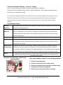
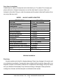
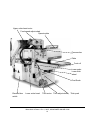
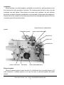
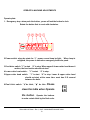
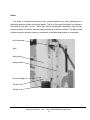
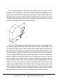
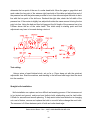
Baker AN-610 Planer
User Manual
Ellington Industrial Supply, Inc.
P. O. Box 128
Ellington, Missouri 63638 USA
Web site: www.baker-online.com
E-mail: [email protected]
Phone: (573) 663 – 7711 Fax: (573) 663 – 2787
Baker AN-610 Planer - Rev 1, 06/07; WWW.BAKER-ONLINE.COM
1
Table of contents
Warranty……..…………………………………………………………….3
Defective Parts………………………………………………………………………3
Service Policy……..…………………………………………………………….3
Rules for Safe Operation………………………………………………………………………4
Control of Hazardous Energy (Lockout / Tagout) ……..…………………………………………….5
Planer Safety Instructions……..…………………………………………………………….6-8
Specification………… ……………………………………………………………9
Machine Installation………………………………………………………………………….9-12
Operate and Machine Adjustments……………………………………………………….13-20
Te s t C u t t i n g … … … … … … … . … … … … … … … … . . … … … … … … … … … … … 2 0
Knif e Installat ion………… ………………………………………………….…………20- 21
Electrical Drawing……………………………………………………………………..22
P a r ts l i s t … … … … … … … … … … … … … … … … … … … … … … … … … … . . … … … … 2 3 - 2 5
Baker AN-610 Planer - Rev 1, 06/07; WWW.BAKER-ONLINE.COM
2
Warranty
Ellington Industrial Supply, Inc. machinery is warranted against defects in material or workmanship starting from the date of
shipment from the manufacturing plant.
This warranty is given solely to the “original purchaser” of the equipment and is in no way to be expressed or implied that it
is transferable to any other parties without the written consent and approval from the CEO or Sales Manager of Baker
Products.
Our one (1) year warranty period covers all items built at our manufacturing facilities including structural frame, cowlings,
doors, shafting, dust chutes and guards.
We honor six (6) months of warranty coverage for miscellaneous vendor-purchased-supplied items including bearings,
chain, sprockets, hydraulic components, etc.
Ninety (90) days of warranty coverage is provided on all electrical parts. All electrical components and wiring has been
installed in accordance with the National Electrical Code (NEC) of the United States of America.
Ellington Industrial Supply, Inc. does not warranty this machine to meet any other requirements or jurisdiction of any
electrical or safety codes of any other state, municipality, other country or jurisdiction The purchaser assumes all risk and
liability whatsoever resulting from the use thereof whether used singularly or in conjunction with other machinery or
apparatus, including, but not limited to, all matters resulting from sawdust generation.
Note: No warranty is provided on any electrical components or parts if equipment is powered or connected to a roto-phase
electrical converter in order to create a three phase power supply for operational current from a single phase source.
Any change in materials, design, or performance intended to improve any product of Ellington Industrial Supply, Inc. shall
not obligate Ellington Industrial Supply, Inc. to modify any previously manufactured equipment.
This manual may contain details that if not properly followed can affect the performance of your equipment. You are
responsible for proper use and maintenance of your equipment and we reserve the right to deny warranty work if deemed
to be caused by a lack of proper maintenance or negligence by the owner or any of their employees.
Defective Parts
Parts claimed defective must be returned freight prepaid, to our plant in Ellington, Missouri. Any part determined defective
due to faulty workmanship or materials will be replaced or repaired (at our option) free of charge, F.O.B. our plant. This
warranty does not cover expendable items (i.e. drive belts, band wheels, conveyor belting, blades, cutters, guides, etc.).
Except as expressly provided herein, this warranty is in lieu of all other warranties, expressed or implied, including a
warranty of merchantability or fitness for a particular purpose. This warranty is “void” if any part of the unit has been
tampered with, modified, altered, or operated with parts other than supplied or recommended by Ellington Industrial Supply,
Inc. In no event shall Ellington Industrial Supply, Inc. be liable for special, indirect, incidental or consequential damages,
however arising, including but not limited to, the loss of earnings or the cost of downtime.
Service Policy
In the event that you have any problems, call us at (573) 663-7711 any time between 8:00 AM and 5:00 PM (CST), Monday
through Friday. A member of our trained staff will answer any questions you may have. We charge nothing for this service.
The only charge is for replacement parts not covered by warranty or after our inspection we deem that the problem is due
to operator error or lack of proper maintenance or neglect.
If it is necessary for a member of our service department to visit your plant at your request, there will be a charge for this
service. Call our service department for current prices.
Retain this Information for your Records
Model Number: …………………… Serial Number: ……………………………………………………………..
Date of Purchase: ………………….Power Source:……………..Dust Removal: ….………………………….
Baker AN-610 Planer - Rev 1, 06/07; WWW.BAKER-ONLINE.COM
3
Rules for Safe Operation
The purpose of safety symbols and signage is to draw your attention to real or possible hazardous conditions that may
exist when operating this equipment. Please remember that safety symbols and signage alone do not eliminate danger and
are not substitute for proper training and education regarding operational hazards.
This symbol and warning indicates a potentially hazardous situation, which, if not
avoided, will result in death or serious injury.
This symbol and warning indicates a potentially hazardous situation, which, if not
avoided, could result in death or serious injury.
This symbol and warning indicates a potentially hazardous situation, which, if not
avoided, may result in minor or moderate injury.
This warning provides notice and instruction regarding a potentially hazardous
situation, which, if not avoided will result in serious injury or death.
SAFETY EXPECTATIONS FOR OPERATING POWER EQUIPMENT
ALWAYS…
•
•
•
•
•
•
•
•
•
•
•
•
ENSURE THAT TRAINED PERSONNEL OPERATE, MAINTAIN AND REPAIR THIS EQUIPMENT
TURN POWER OFF AND LOCKOUT / TAGOUT PRIOR TO PERFORMING MAINTENANCE
KEEP WORK AREA CLEAN AND WELL LIGHTED TO MINIMIZE OR ELIMINATE HAZARDS
KEEP CHILDREN AND VISITIORS AWAY FROM OPERATING EQUIPMENT
OPERATE THE EQUIPMENT AT THE RATE IT WAS DESIGNED FOR
KEEP GUARDS IN PLACE WHEN OPERATING EQUIPMENT
REMOVE TOOLS BEFORE RESUMING OPERATION
USE PROPER EXTENSION CORD
WEAR PROPER APPAREL AND AVOID LOOSE CLOTHING AND ACCESSORIES THAT COULD GET CAUGHT
IN MOVING PARTS
ALWAYS WEAR SAFETY GLASSES AND HEARING PROTECTION
AVOID “KICK-BACK” BY KNOWING WHAT CONDITIONS CAN CREATE IT
CHECK DAMAGED PARTS AND REPAIR OR REPLACE THEM IMMEDIATELY
NEVER…
•
•
•
LEAVE MACHINERY RUNNING OR UNATTENDED, ALWAYS TURN POWER OFF
OPERATE EQUIPMENT WHEN TIRED, FATIGUED OR UNDER THE INFLUENCE OF DRUGS OR ALCOHOL
ALLOW UNTRAINED PERSONNEL TO OPERATE, MAINTAIN OR REPAIR THIS EQUIPMENT
No list of safety expectations can ever be complete as every work environment is as different as
are the people operating the equipment.
Always keep safety as your highest priority and always use this machine with caution and
respect.
Baker AN-610 Planer - Rev 1, 06/07; WWW.BAKER-ONLINE.COM
4
Control of Hazardous Energy – (Lockout / Tagout)
Lockout / Tagout (LOTO) refers to specific practices and procedures to safeguard
employees from the unexpected energy, startup of machinery/equipment, or the release of hazardous energy
during service or maintenance activities.
This requires that a designated individual turn off and disconnect the machinery/equipment from its energy source(s)
before performing service or maintenance and that the authorized employee(s) lock and tag the energy-isolating
device(s) to prevent the release of hazardous energy and take steps to verify that the energy has been isolated
effectively.
List of Related Terms
Affected
An employee whose job requires them to operate a machine or piece of equipment on which service or
Employee
maintenance is being performed.
Authorized
A person who locks or implements a tagout system procedure on machines or equipment to perform
Employee
service or maintenance on that machine or equipment. An authorized employee and an affected
employee may be the same person when the affected employee's duties also include performing
service or maintenance.
Energy Source
Any source of electrical, mechanical, hydraulic, pneumatic, chemical, thermal, or other energy.
Lockout
The placement of a lockout device (such as a lock) on an energy-isolating device, in accordance with
an established procedure that ensures the device and the equipment cannot be operated until the
lockout device is removed.
Servicing and /
Workplace activities such as constructing, installing, setting up, adjusting, inspecting, modifying,
or Maintenance
maintaining or servicing machines or equipment. These activities include lubrication, cleaning or
un-jamming of machines or equipment, and making adjustments or tool changes where the employee
may be exposed to the unexpected energy, start-up of equipment or release of hazardous energy.
Tagout
The placement of a tagout device (such as a tag) on an energy-isolating device, in accordance with an
established procedure that ensures the device and the equipment may not be operated until the
tagout device is removed.
Example of lockout tags, lockout hasp
and keyed lock
The Fatal Five Main Causes of Lockout/Tagout Injuries
1. Failure to stop equipment
2. Failure to disconnect from a power source
3. Failure to dissipate (bleed, neutralize) residual energy
4. Accidental re-starting of equipment
5. Failure to clear work areas before re-starting
Baker AN-610 Planer - Rev 1, 06/07; WWW.BAKER-ONLINE.COM
5
SAFETY FIRST!
This manual has been prepared for operators of the planer. It’s purpose, aside from
machine operation, is to promote safety through the use of accepted operating practices.
Read the safety and operating instructions thoroughly before operating the machine.
PLANER SAFETY INSTRUCTIONS
Read, all these instructions before operating the planer. Know the limitation and
hazards associated with this planer. A safety rules decal is on each machine to serve as a
reminder of basic safety practice.
Grounding of the planer: make certain that the machine frame is electrically grounded and
that a grounding lead is included in the incoming electrical service, in cases where a cord
and used, make certain that the grounding lug connects to a suitable ground. Follow the
grounding procedure indicated by the national electric code.
Work area clean : keep the floor around the machine clean and free of scrap material,
sawdust, oil or grease to minimize the danger of tripping or slipping. Be sure table is free of
all scrap, foreign material and tools before starting a cut.
Dress properly: before operating the machine, remove, tie, watch and other jewelry and
roll up sleeves above the elbows. Remove all loose clothing and confine long hair.
Protective type footwear should wear and hearing protectors should be used where noise
exceeds the level of exposure allowed in section OSHA regulations. Do not wear gloves.
Wear safely goggles: wear a proved safety shield, goggles, or glasses to protect eyes
when operating the planer.
Hand safety: keep hands outside the machine. Never reach under the guards to try to clear
stock that stops feeding. Do not clear chips and sawdust with hand; use a brush. Notice
caution decal at rear of the machine. Do not have any part of the hands any part of the
hands under that part of the board that is over the table when starting a cut; the infeed roll
will engage the board and force it down against the table causing a pinching action.
Don’t overreach: keep proper footing and balance at all times.
Guards: keep the machine guards in place at all time when the machine is in use. If
Baker AN-610 Planer - Rev 1, 06/07; WWW.BAKER-ONLINE.COM
6
removed for maintenance purposes, use extreme caution and replace the guards on
completion of the maintenance task before using the planer. Do not operate the machine
with the guards off.
Keep children away: Do not let on lookers contact or power lead. All onlookers should be
kept away from work area.
Operator position: stand to the left side out of line with the table and make sure no one
else is standing in line with the table.
Maintain tool in top condition: keep tools sharp and clean for safe and best performance.
Dull tools increase noise levels and can cause kickbacks and glazed surfaces. Broken tool
or tools that are not securely locked in the cutter head can be thrown out of the planer
causing sever or fatal injury as well as severe damage to the machine. Do not use knives
that have been reground to less 3/4”(19mm) height on standard cutter head
Cutter head rotation: be sure cutter head rotates under power in a counterclockwise
direction when viewed from the main drive motor side.
Machine adjustments: make all machine adjustments with power off except feed rate
Use the right Machine for the job: Do not make any cuts requiring more power than
available on the machine. Each machine has a caution decal on the front panel indicating
the maximum depth of cut and the maximum difference in board thickness allowed when
multiple board surfacing when it is equipped to do that operation. Do not attempt to feed two
boards side by side on any machine not equipped with a sectionalized infeed roll and chip
breaker.
Material condition: Do not planer boards with loose knots or with nails or any foreign
material on this surface. Knife impact on these objects can cause the knives to be pulled out
and cause them to shatter against the chip breaker or pressure bar. Twisted, warped, or in
wind stock should first be jointed on one surface before attempting to plane a parallel
surface stock flaws cannot be removed by use of a planer alone.
Stacked boards: Do not feed stacked board through a planer; a kickback can occur
Baker AN-610 Planer - Rev 1, 06/07; WWW.BAKER-ONLINE.COM
7
causing sever or fatal injury.
Short stock: do not attempt to plane boards shorter than 10”(250mm) in length without
butting aboard of equal thickness behind it to help it through the planer. Be sure the last
board of a butted sequence is 250mm long or longer.
Stock stop feeding: if the board being planed stops feeding, disengage or turn the fee off
and turn the power off. Wait until the cutter head comes to a complete stop before lowering
the table to remove the board. Never lower the table with the power on and the stock still in
the machine. A kickback can occur which could cause a severe or fatal injury.
Avoid accidental starting: Be sure switch is turned off when connecting power to the
plane.
Stay alert: Watch what you doing. Use common sense. Do not operate planer when you are
tired.
Job completion: If the operator leaved the machine area for any reason, the planer should
be turned “off” and the cutter head should come to a complete stop before his departure. In
addition. If thee operation is complete, he should clean the planer and the work area. Never
clean the planer with power “on” and never use, the hand to clear sawdust and debris; use a
brush.
Disconnect machine: when not in use, before servicing and changing accessories such as
blades, knives.
Baker AN-610 Planer - Rev 1, 06/07; WWW.BAKER-ONLINE.COM
8
Save these instructions
Listed below is a table of horsepower and cutter head r.p.m. For planer. Do not equip your
planer with motor of higher horsepower nor run the cutter head in excess of the r.p.m.
Indicated in the table. Doing so voids the warranty and the planer holds itself harmless from
any injury that may result.
MODEL: AN-610 PLANER CAPACITIES
SPECIFICATION
Model 610
Table area
26”x102” (680*2600mm)
Cutter head diameter
5” (124mm)
Cutting circle
5” (126mm)
Max. cutter head R.P.M
4000 rpm
Knife size(4 pcs)
¼”x 1.5”x24” (6.0x38x610mm)
Infeed roll diameter
4” (100mm)
Out feed roll diameter
4” (100mm)
Bed roll diameter
4” (100mm)
Feed m.p.m.
23’-52’ ft/min (7-16m/min)
Max depth of cut single board
½” (12mm)
Stock range thickness
¼” – 7” (3-170mm)
Widest planeable butted stock
24” (610mm)
Shortest planeable stock not butted 8” (200mm)
Motors
15Hp/10Hp
Approximate weight
7,300 lbs (3300kgs)
Machine installation
Receiving:
Uncrate machine and check for shipping damage. Report any damage to the carrier and
your distributor immediately. If accessories were ordered with the machine, these will be in a
separate container and should be checked for completeness and damage. Notify the carrier
and your distributor immediately if any items are missing or damaged. Clean protective
coating from all areas and lubricate parts as indicated in this manual.
Baker AN-610 Planer - Rev 1, 06/07; WWW.BAKER-ONLINE.COM
0
9
Upper cutter head motor
Feed speed adjust wheel
Operate plate
Pressure bar
Table
Front roll
Lower scale
Lower thick
wheel
Final Scale
Electrical box
switch
Lower cutter head
Thick motor
Thick adjust wheel
Baker AN-610 Planer - Rev 1, 06/07; WWW.BAKER-ONLINE.COM
1
10
Thick push
Installation:
Mount machine on a solid foundation, preferably a concrete floor, and lag machine to the
floor through the holes provided in the base. The machine area should be clean, dry well
ventilated, and well lighted. Since planer can create noise problems, the site selection
should be one which minimizes reverberant sound from walls, ceilings and other equipment.
Electrical should be installed so that they are protected from damage and exposure. Be sure
to properly ground the machine frame.
torque limiter for transmission
system
Feed drive system
upper cutter head motor
Dust hood
infeed roll
outfeed roll
Table roll
Lower cutter head
dust hood
lower cutter head motor
Exhaust system:
When an exhaust system is used, be sure it is of sufficient size to provide volume of 36
cubic meter/min. If exhaust system is not user, the user is cautioned against the health
hazard.
Baker AN-610 Planer - Rev 1, 06/07; WWW.BAKER-ONLINE.COM
2
Inspection:
Before putting power on the machine, check that all screws are tight, that all mechanical
functions work freely and that the cutter head turns
11 freely without knife contact with the chip
breaker or pressure bar. Periodic or regular inspections are required to insure that the
machine is in proper adjustment, that all screws are tight, that belts are in good condition,
that dust has not accumulated in the electrical enclosures, and that there are no loose or
worn electrical connections.
Before operating:
Check the motor and switch wiring diagram for proper voltage connection before
applying power to the machine. Turn the main drive motor on momentarily to check
for proper direction of rotation. Correct as required. Cutter head should rotate
counterclockwise when viewed from the sheave or motor side. The infeed roll should
turn clockwise when from the motor side planer. Run the machine without cutting for a
short period of time to check that all power function are operating properly. Be sure to read
and understand the operating instruction manual using the planer.
Lubrication:
The table roll, infeed roll and outfeed roll are mounted on sealed ball bearing and require
no lubrication. The
Cutter head housing
Daily
High speed Grease following lubrication
chart indicates the
slider ways
Weekly
SAE32
lubrication
points,
feed chain
Weekly
SAE32
frequency,
and
Fd. Drive gears
Weekly
SAE32
recommended
lubrication.
Baker AN-610 Planer - Rev 1, 06/07; WWW.BAKER-ONLINE.COM
3
OPERATE & MACHINE ADJUSTMENTS
Operate plate:
1. Emergency stop: when push the button , power off and the button be lock.
Rotate the button that to reset with clockwise.
2.Power switch: when be rotate for “1” ,power on and lamp be light . When lamp is
unlighted, the power is unload or emergency button be push.
3.Feed drive switch: ”1” is start “0” is stop. When upper & lower cutter head doesn’t
motion, the feed motion should not start.
4.Lower cutter head switch: ”1” is start “0” is stop.
5.Upper cutter head switch: ”1” is start “0” is stop. Lower & upper cutter head
should not start at the same time. must has 5-10 second
between the both..
6.Final thick switch: ”↑ ”be thick, ”↓” be thin.
Please
clean the table when Operate
the button.
Operate the buttons
to make certain thick by the final scale.
Baker AN-610 Planer - Rev 1, 06/07; WWW.BAKER-ONLINE.COM
4
13
Slider:
The slider is raised and lowered by four screws supported on thrust bearing and is
guided by machine surface on the side panels. The fit-up to prevent the table from rocking is
controlled by two gibs in front. These gibs should be adjusted individually using the gib
screws provided, so that the ways are lightly contacting on all four surfaces. The gibs should
be tight enough to prevent rocking or movement of the table when planer is in operation.
nut & setscrew
gibs
sliding block
sliding bottom
Pressure block
Screw nut
Screw
Baker AN-610 Planer - Rev 1, 06/07; WWW.BAKER-ONLINE.COM
514
To do accurate planning, the slider must be parallel with the cutter head. Lack of
parallelism results a taper over the width of the board. Check with straddle-type knife
gage to insure knives have the same protrusion from the cutter head arc end to end
that each knife is the same. Maximum deviation allowed for good planning is 0.02mm.
If deviation exceeds 0.02mm, see section on installing cutter head knives or section
on jointing and riding knives before leveling the table.
Place 125*125mm gage block and shop scale to be used as a feeler gage or bed
and table roll gage at the extreme right hand side of the table, rotating head so the
knives clear the gage surface. Raise the table with the table raising hand wheel until
the scale on top of the block just touches the cutter head. Move the block to the
extreme left side of the table. Using the block, find the low point of the cutter head are
without moving the table height. Note whether the reading is less than or greater than
left side, if greater on the left side, the left side of the table must be lower; if less, the
left side of table must be raised. With the indicator or gage block under left side that
must be raised or lower, loosen the lock screw locking the threaded flange nut from
rotation in the table on the side to be raised, lower. Rotate the nut using a rod in the
flange holes and adjust height of the left side. Relock the flange nut lock screw in the
table. Another method that can be used if the table is free is to loosen the lock screw
on the high side of the table and then rotating the table hand wheel clockwise raising
the opposite side until it is level. Relock the flange nut lock screw in the table.
Baker AN-610 Planer - Rev 1, 06/07; WWW.BAKER-ONLINE.COM
6
15
Table rolls:
Two table roll are provided on the planer to help reduce the friction of the stock on the
table as it feeds through the machine.
To adjust the bed roll setting. If using a bed and feed roll gage, zero the indicator to the
table. Place the over the extreme right side If the table roll and find the high point of the
roll arc. The standard setting is 0.5mm. If the reading is greater or less than this reading,
loosen the nut ,and adjust the hex head jackscrew to position the roll the 0.5mm setting.
Repeat the process on the left side and than recheck the right side. Relock the nuts.
Table rolls
Table roll set screw
outfeed roll
limiter
infeed roll
Baker AN-610 Planer - Rev 1, 06/07; WWW.BAKER-ONLINE.COM
716
Infeed roll:
The function of the infeed roll is to feed the material into the machine. It is a
corrugated roll and when sectionalized is made up of one inch wide sections with 6mm
movement in each section to accommodate multiple board surfacing. In addition, the
whole assembly is rubber loaded to accommodate the full 6mm depth of cut. To provide
proper drive, it should be set so that the bottom of its arc is 1.6mm on sectionalized type
below the arc of the cutter head knives. Using gage block or a short piece of finished 2*4
lumber notched to clear the table roll placed on edge under one knife of the cutter head,
raise the table with the table raising hand wheel and rock the cutter head back and forth
until it just touches the gage block or 2*4. a shop sale of the proper thickness, 1.6mm can
be used on top of gage block when touching off under the knives and then removed when
setting the infeed roll to provide the correct step down, lower the table 1.6mm and move
the 2*4 or gage block under the extreme right hand side of the infeed roll. If it will not go in
the roll must be raised. If clearing, it must be lowered. Using the setscrews provided
unlock the setscrew and adjust as required so that the roll just touches. Move the 2*4 to
the extreme left side and adjust that side as required until the roll just touches the gage.
Recheck the right side and then lock the setscrew with the jam nuts provided. The most
accurate method of setting infeed roll with the bed and feed roll gage. Find the low point
of the knife arc to the end of the page then set the infeed roll to 0.062 for sectionalized
infeed roll below the zero point. It is important that that the setting on both sides of this
feed roll be close to the sane height to help avoid skewing of the material as it is fed
through the machine. Infeed roll pressure is controlled by springs and is adjusted by use
of screws locate on top of the side panels pressure should be slightly higher on the drive
side to help avoid skewing of board as it feeds through, the adjusting screw will be
approximately flush with the bottom of the countersink on the top side panels when
properly adjusted.
Baker AN-610 Planer - Rev 1, 06/07; WWW.BAKER-ONLINE.COM
8
Chip breaker
17
chip breaker set screw
press bar set screw press bar
Chip breaker:
The sectionalized chip breaker is constructed of 25.4mm wide spring-loaded section
mounted on a bar. Each section has approximately 6mm independent yield. The function of
the chip breaker are to help avoid splintering out of the wood, to break chip into small pieces,
to help avoid board bounce on thinner boards, to direct the flow of chip out of the machine,
and to permit multiple board surfacing up to 6mm difference in thickness.
The chip break in its free position should be 0.8mm below the cutting arc of the knives:
the same as the infeed roller. Using the same method as indicated for the infeed roller,
adjust the chip breaker free position using 2*4 gage block and shop scale of the proper
thickness and adjusting screws in the pivot arm at each end. It is important that each end be
close to the same height to help avoid skewing of the material as it is fed through the
Baker AN-610 Planer - Rev 1, 06/07; WWW.BAKER-ONLINE.COM
9
18
machine. Since the chip breaker adjusting screws contact the bearing house for the infeed
roll, its adjustment should be made after the infeed roll and if the infeed roll setting is altered,
the chip breaker must be readjusted.
Caution: a chip breaker set too low may prevent stock from feeding into the machine.
Out feed roll:
The outfeed roll is smooth and of one-piece construction to help avoid marring the
finished surface of the material being cut. Its function is to continue to feed the material
through the machine after it leaves the infeed roll. The correct free position setting is .8mm
below the arc of the cutter head knives. Using the gage block or a finished 2*4 on edge with
0.8mm shop scale on top under the cutter head, raise the table and rock the cutter head to
establish the low point of the knife arc. Remove the scale and position the gage or 2*4 under
the right side of the outfeed roll. Raise or lower its right hand bearing support with the
setscrews provided to a light drag fit. Move the gage or 2*4 under the left hand end and
adjust in the same way. The most accurate method of setting the outfeed roll is with the bed
and feed roll gage. Zero the gage to the low point of the cutter head arc and set each end of
the outfeed roll to 0.8mm below the zero on both sides. Lock the setscrew with the jam nuts
provided. Out feed roll press is controlled by springs and is adjusted by use of screws by
use of screws located on top of side panels. The top of the adjusting screw will be
approximately flush with the bottom of the countersink on the top of the side panels when
properly adjusted. Care must be observed in marking this adjustment. So that slightly more
pressure is exerted on the driving side. Unbalanced pressure can result in skewing of the
board as it feeds through.
Pressure bar:
Most planning problems can be related to improper setting of the pressure bar. Its
function are to hold the material down after it pass under the cutter head and throughout the
remainder of the cut. Its basic setting is to be in line with the arc of the cutter head knives. If
it is too high, a shallow clip will occur in from each end of the board. If it is too low, stock will
not feed through.
With a bed and feed roll gage or a gage block and a 0.8mm thick 150mm scale as a
feeler placed under the cutter head, raise the table with its elevating hand wheel to
Baker AN-610 Planer - Rev 1, 06/07; WWW.BAKER-ONLINE.COM
10
19
determine the low point of the arc of a cutter head knife. Move the gage or gage block and
scale under the low point of the extreme right hand side of the table and adjust that end of
the pressure bar with the jackscrews provided to be in line side and adjust that side to be in
line with the low point of the knife arc. Recheck the right side; check the full width of the
pressure bar. If the center is slightly low, adjust both sides the same amount to bring the low
point into line. Using the bed and feed roll gage set the full length of the pressure bar to be
0.02mm above the arc of the cutter head. This initial setup is starting point and final
adjustment may have to be made during a test cut.
Test cutting:
Using a piece of semi-finished stock, set up for a 1.5mm deep cut with the quick-set
adjustment zero. Start the machine, and standing to the left-head side begin feed the stock
into the machine
Straight knife installation:
Knife installation on a planer can be a difficult and exacting process. If the knives are not
to be jointed and ground, end-to-end and knife-to-knife relationship must be held within
0.03mm for accurate and smooth planning. To help avoid cutter head distortion in changing
out a set of knives, remove and replace the knife in one slot before change the next knife.
The measure is 3.00mm between point of knife and cutter head edge.
Baker AN-610 Planer - Rev 1, 06/07; WWW.BAKER-ONLINE.COM
11
20
1. Clean all dust, chip, pitch and
accumulated foreign matter from a cutter
head slot and off of its gib.
2. Working with one slot, with the knife and
gib against each other and the beveled
surface of the knife on the knife spring
and the concave shaped surface of the
gib up, insert into the slot. The back edge
of the knife bevel should be slightly below the outside diameter of the cutter head
3. Press the knife with knife gage Lightly tighten two outside and center gib screws.
4. Repeat the preceding method on successive knives making sure that the height from
knife to knife is the same within 0.03mm. Loosen gib screw to establish the high point of
the knife. To touch the knife gage.
5. After all knife have been installed, recheck all gib screw to be sure they are tight, loose
gib screws can result in knife being thrown out of the cutter head causing severe
damage to the machine and possible serious or fatal injury to the operator or bystanders.
Note: If all knives have been removed, a new set must be installed without locking the gibs
until all knives and gibs are in and the gib screws lightly snuggled down. The locking
process should precede working from the center out on each knife and locking all gib screw
once, repeat the same sequence until all screws are equally tight. Locking one knife in
without the others in position can cause cutter head distortion.
Removal of knives:
1. Loosen all gib screws in one slot.
2. Remove both knife, gib.
3. Repeat step 1 & 2 for the remaining knives
Helical cutter head inserter installation:
1. Check cutter head inserter size 14*14*2.0 angle 30°
2. Clean cutter head & inserter, set the inserter in position, apply oil on M6*1.0 screw
3. Adjust air pressure as 2kgs/cm2 to pre –set the inserter.
4. When finish the pre-setting of inserter, adjust air tool pressure as 6kgs/cm2 to tighten screws. The torque
is 55-58 kgf-cm
5. when don’t able to remove screw/inserter, use the bar & screw drive, knock it slightly by a hammer ,turn
counterclockwise to remove at the same time.
Baker AN-610 Planer - Rev 1, 06/07; WWW.BAKER-ONLINE.COM
12
21
Electrical Drawing
Make certain that the electrical power volt accord with motor volt & motor contact method.
Check the motor direction is counterclockwise.
Grounding of the planer: make certain that the machine frame is electrically grounded and
that a grounding lead is included in the incoming electrical service, in cases where a cord and
used, make certain that the grounding lug connects to a suitable ground. Follow the grounding
procedure indicated by the national electric code.
Baker AN-610 Planer - Rev 1, 06/07; WWW.BAKER-ONLINE.COM
13
22
Parts List
ITEM DESCRIITION
QTY
35
Bar of motor rack
1
1
Thrust bearing 5105
8
36
Pulley of 8”1/4
1
2
Bevel gear 24t
4
37
Key 8*20
1
3
Rack of raising screw
4
38
Bearing 6006
4
4
raising screw Left.
2
39
cover of house
2
5
Hex hd. Cap.M10*40
8
40
Chain pulley #50/20t
1
6
M10 washer
8
41
Chain pulley #50/20t
1
7
Pressure nut block
4
42
Cover of house
2
8
Raising nut belt
2
43
cover of bearing house
2
9
Bevel gear 14t
4
44
Cap hd cap. M10*30
4
10
Bearing 6005
4
45
Cutter head
1
11
Ring R-52
4
46
Hex hd cap M20*80
1
12
Chain pulley #50/20t
2
47
Nut M20
1
13
Raising Shaft
2
48
Support of cutter head house
1
14
Key 7*25
2
49
Slide block
2
15
Slider block L.H.
2
50
Cover of house
1
16
Gib
4
51
Nut M40*1.5
1
17
Slider L.H.
2
52
Bearing 6308
2
18
Raising nut R
2
53
Bearing bridge
1
19
Slider R.H
2
54
Race
2
20
Slide block R.H.
2
55
Cover of housing
1
21
Chain pulley #50 /15
1
56
Pulley 3”
2
22
Worm-gear mechanism
1
57
Nut M35*1.5
2
23
Raising Motor 1/2Hp 4ph
1
58
Hex hd cap M10*80
4
24
Chain pulley #50 /15t
1
59
Nut M20
2
25
Hand wheel
1
60
Hex hd cap M10*80
1
26
Chain pulley rock
1
61
Hex hd cap M20*1.5
1
30
House of table roller
4
62
Lower body
1
31
Table roller
2
63
Hex hd cap M10*60
4
32
Shaft of Table roller
2
64
Hex hd cap M20*1.5
8
33
Lower cutter head motor
1
65
Rear plate
1
34
support of motor”
1
66
Rear table
1
Baker AN-610 Planer - Rev 1, 06/07; WWW.BAKER-ONLINE.COM
14
23
67
Front plate
1
102
Chain pulley #50/20t
1
68
Front table
1
103
Cap M12”
4
69
Slide block of table
1
104
Screw bolt
2
70
Gib, front table
1
105
Spring for roller
4
71
Nut block
1
106
Cap nut m24*1.5
4
72
Screw, front table
1
107
Cap bolt M4*1.5
4
73
Thrust bearing 2905
2
108
Nut,M12
8
74
Thrust block
1
109
Bracket Nut, L.H.
1
75
Thrust bearing 2905
2
110
Infeed Roller block
12
76
Hand wheel
1
111
Infeed roll Shaft
1
80
Cover of house
1
112
Spring for infeed roller block
72
81
Bearing 6208
2
113
Spring block
72
82
House of bearing
1
114
Bracket nut,R.H.
1
83
Chip breaker hanger.
2
115
Chain pulley #50/20t.
1
84
Pressure bar hanger
2
116
Gib for knife
2sets
85
Upper cutter head
1
117
Straight knife
2sets
86
Pressure bar
1
118
Cap screw M6*30
16
87
House of bearing
1
130
Cam plate
1
88
Cover of house
1
131
Cam drum
4
89
Chip breaker
12
132
Chain slider L.H
1
133
Housing-bearing
2
134
Housing-bearing rack
4
90
Bracket, for chip breaker,
L.H.
1
91
Plate of chip breaker.
1
135
Pull block
1
92
Screw bolt,
12
136
Key 10*8*40
4
93
Spring, for chip breaker
12
137
Cap nut M20r
2
94
Bracket, for chip breaker, R.H
1
138
Chain pulley #2100/12t
4
95
Plate of cutter head house
1
139
Chain shaft
1
96
Cover for house
2
140
Cam shaft
2
97
Ring S-35.
2
141
Chain slider R.H
1
98
Bearing 6007
6
142
Lower plate of pawl
52
99
house
2
143
ring
104
100
Out feed roller
1
144
pawl
1144
101
Cover
2
145
Spring 0f pawl
1144
Baker AN-610 Planer - Rev 1, 06/07; WWW.BAKER-ONLINE.COM
15
24
146
ring
52
147
Chain pulley #50/15T
2
148
Cam shaft
1
149
upper plate of pawl
52
151
Chain #2100/52t
2
152
Housing bearing
2
153
Motor support
1
154
Chain support
2
155
Key 7*7*30
6
156
Chain shaft
1
157
Upper body
1
158
Pulley 8’1/4”
1
159
Motor 15Hp 4ph
1
160
Torque drive body
2
161
Disk lining
1
162
ring
1
163
Chain pulley #60/37t
1
164
Chain ring
1
165
Chain pulley #50/46t
1
166
Pressure disk
1
167
Disk string
1
168
Supply disk
1
169
Pressure nut
1
Baker AN-610 Planer - Rev 1, 06/07; WWW.BAKER-ONLINE.COM
16
25