1
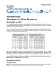
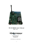
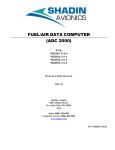
Using LabVIEW with Honeywell’s Precision Pressure Transducer (PPT)
AN-105
Preliminary
This application note describes National Instrument LabVIEW (LabVIEW is copyrighted software from National Instruments, Austin, TX) “Virtual
Instrument” routines for interfacing to Honeywell’s serial output Precision Pressure Transducers, the PPT and PPT-R. Data Sheets for these products
are available on the Honeywell SSEC website at www.ssec.honeywell.com. (A LabVIEW “Virtual Instrument” consists of a user interface called the
front panel, consisting of a mix of controls and indicators. The graphics-based program code is contained in the associated block diagram.)
These Virtual Instruments (VIs) were written by Honeywell specifically for the PPT family and are downloadable from our website at
www.ssec.honeywell.com. Only a very basic familiarity with running LabVIEW is necessary to use the VIs as-is. The second section of the note
describes in detail how a VI for charting and data taking was constructed. The user can build upon this example to create a PPT-interface VI with
customized capabilities. This section also provides some general comments on interfacing to a multi-unit PPT network using a VI.
Background
The PPT and PPT-R provide pressure readings in digital format (ASCII text) along with a conventional analog output. Users can send commands to
the PPT and receive data from it through the digital interface using a PC and terminal emulator software, such as Hyperterminal (Hyperterminal is
copyrighted software from Hilgraeve, Monroe, Michigan). Factory default settings establish all key parameters such as update rate, allowing quick
utilization of the PPT once communication through the serial port is established. When the user is familiar with the PPT performance and command
syntax, changes from the factory settings can be made to tailor the output to the specific measurement requirements. If the new settings are stored, they
will be the new defaults each time the PPT is powered-up.
Terminal emulator software is inadequate for some data taking needs. Yet the words “serial port programming” may cause a cringe of apprehension
for the user seeking an enhanced capability. The Virtual Instrument routines described in this note provide LabVIEW users with an easily executed
interface to the PPT for establishing communications, issuing commands, configuring the device, charting data real-time and storing data to text files.
Note: The LabVIEW VIs discussed here assume a PPT with RS-232 communication, or RS-485 communication with an in-line converter from
RS-485 to RS-232. PPT power and data communication requires a data cable/power supply available from Honeywell, or the user may fabricate the
required cables using the wiring diagram information in the PPT User Manual and appropriate connectors.
1. Virtual Instruments Routines for the PPT
This section of the note describes the functions of the Virtual Instruments written for the PPT, and discusses common serial port communication
problems. There are a few general examples of serial port VIs provided with LabVIEW, but not much written material on the topic of serial port
programming. The Honeywell PPT-specific VIs are contained in a library file, <PPT Demo.llb>. The top level VI, <PPT Master.vi>, provides the user
interface to a set of “Sub VIs.” All these VIs are built using only the native capabilities available within LabVIEW software. The Master VI and the Sub
VIs in this file follow.
PPT Master .VI
This VI is the interface for several Sub-VIs used to communicate with PPTs. The selected “Run This” Sub VI menu item will execute when the RUN
button is pressed. (In the example below the COM port will be initialized when the RUN button is pressed.)
1
Sub VI: <Find Ports.vi>
Uses NI-VISA functionality to find serial ports installed on your PC.
Sub VI: <Serial Port Init.vi>
Initializes Serial port of choice to PPT default communication protocol.
Sub VI: <Single Write Read.vi>
The Serial Communication VI performs bi-directional communication with a port. It initializes the port, writes a string to the port, and
performs a read with time-out. The Read with Timeout VI will wait until the reply is available (Carriage Return received) or the time limit
is up, whichever comes first.
Although it is not a full-fledged terminal software application, it does provide sufficient functionality to demonstrate how to communicate with a Honeywell PPT using LabVIEW.
Sub VI: <Configure.vi>
Identify Serial Number, pressure units, change pressure units of PPT
2
Sub VI: <PPT Chart 2.vi>
Real time plot of PPT data, and enables the user to save the data in a Tab delimited text file.
Common Problems During Serial Communication:
Most problems are in the software, not the hardware. Use the example VIs as a reference point for ways to send a command to the PPT,
parse the returning ASCII text, and implementation of at least rudimentary error handling.
Program hangs up: A common problem is reading serial data, and expecting a certain number of characters in the response. If there are
not the specified number of characters at the serial port the program waits there indefinitely, hung-up. The examples provided use
<Read with Timeout.vi>, returning an error if the read operation does not complete within a couple of seconds. Rather than request
a fixed number of characters, a request for a single character is repeated until the PPT end of message character, a Carriage Return,
is received. (A second, less common source of timeout error selecting the wrong COM port, and trying to communicate with a PPT
through the wrong COM port.)
Termination Character: Serial communication can be challenging to use for device control. The key is making sure the command syntax
is exact, no extra characters or spaces, and terminated with a Carriage Return as required by the PPT.
Incomplete/Incorrect Data Transfer: A common problem occurs when a read operation on the serial port does not return the string of
characters expected. This may happen because a Read operation happens before the Write operation completes. This can be resolved
by using Sequence structure and/or data dependency. Refer to the sample VIs for examples of these techniques.
2. Constructing a LabVIEW Virtual Instrument for the PPT
In this section the construction of a VI for communication and charting data is described so the user can understand the techniques involved
and create modifications if desired. A basic familiarity with the LabVIEW methodology for building Virtual Instruments is assumed.
<PPT Chart 2.vi> incorporates all the basic functionality for communication with a PPT:
•
Serial port initialization
•
a serial port “WRITE” to request a single pressure reading
•
a serial port “READ” to capture the reply
•
Parsing the reply to separate the response from the echoed command, extracting the numeric portion of the reply for charting and
adding to an array, and finally, writing the array into a Tab-delimited text file for use in a spreadsheet program.
The block diagram shown below is described in detail by separating it into three areas:
1) Front panel and serial port initialization
2) Write and Read operations
3) Extraction/charting/saving of the numeric portion of the response. The complete block diagram is included on the last page for reference.
3
Networked PPTs:
The example VIs discussed communicate with a single PPT. However, each PPT is individually addressable, and it is possible to build
a network of PPTs if they have been assigned unique IDs. A PPT ring network utilizing the RS-232 protocol may contain as many as 89
PPTs. A multidrop network is possible with RS-485 PPTs. The RS-485 standard allows a maximum of 32 units on a single bus, but to
accommodate more than this some of the allowed units can be repeaters. Each repeater can add an additional 32 units, up to the maximum
allowable 89 PPTs on a network. (Implementation of appropriate For-Loop Structures, dynamic command construction, and parsing of
the PPTs responses are beyond the scope of this note. Request the PPT Users Manual for further information.)
Diagram 1: Front Panel and Serial Port Initialization
“START” button FALSE: No action is required. A delay of 250 milliseconds is required.
“START” button TRUE:
Frame 0 of the sequence: Initialize the “Read String” front panel indicator to the Null String.
Frame 1 of the sequence: Initialize the Serial port, (passed from the Calling VI).
4
(The default PPT communication conditions of 9600 baud, 8 data bits, no parity and one stop bit.) A Boolean value indication of whether
or not there was a port initialization error is passed to the Case structure within the adjacent While Loop.
Front Panel Setup:
The On/Off colors of the front panel error lights are changed from the default colors to red/gray. (No color change is required for
functionality). This VI uses two different methods to accomplish this. The “Serial Error” indicator default colors are modified by passing
an array of the necessary 32 bit integers to the attribute node (See LabVIEW help for the specifics on determining the appropriate numeric
values). The “Read Timeout” indicator default colors are modified by building an array of clusters made from color box constants, and
passing the resultant array to the applicable attribute node. Note: the electronic version of this note is in full color.
Diagram 2: Write request for a single pressure reading, Read and parse the PPT reply.
5
Initialize the shift register to the Empty String.
Serial Init Error: the True case displays “ERROR” in the Read window, and the error condition is passed to the next Case structure.
No Serial Init Error: the command to request a single pressure reading is built, and written to the Serial port. Error status of the Write
function passes to the adjacent Case structure.
Write Error: No Read take place, set the Read string to Null, and pass an error to the next Case structure.
No Write Error: Read one character at a time. Concatenate to the Shift Register contents and repeat the process until the returned
character is a Carriage Return, or the Read operation times out. When a Carriage Return is received, pass the Shift Register contents and
error status to the next Case statement.
Diagram 3: Extract numeric data, Chart data, add to data array, write data to file.
Read Timeout Error True: Send some atypical data point to the Chart and data array (like a 0).
No Read Timeout: Extract the numeric portion of the PPT response. Send this value to the Chart, as well as adding to the data array. The command
written to the PPT will be echoed after the reading, so perform another Read operation to clear out the buffer. ( See how many characters are
in the buffer, and Read that number of characters.)
The While loop checks the status of the Start switch. If it is still True, no additional action is required. If the Start switch has been turned Off,
the data array is transposed and written to a Tab delimited text file. Upon return to the calling VI, the serial port will be closed
6
Diagram 4: PPT Chart 2 Block Diagram
Conclusion
With LabView users can create a PPT-interface VI with custom
capability for both single units and multiple-unit PPT networks.
Users can easily execute interface to the PPT for establishing
communication, issuing commands, configuring the device, charting
data real-time, and storing to text files.
Contact Information:
Customer Service: (800) 323-8295
www.ssec.honeywell.com
Honeywell reserves the right to make changes to any products or technology herein
to improve reliability, function or design. Honeywell does not assume any liability
arising out of the application or use of any product or circuit described herein; neither
does it convey any license under its patent rights nor the rights of others.
900259
6/00
7