1
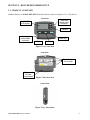
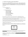
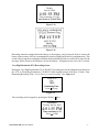
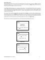
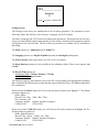
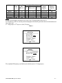
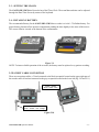
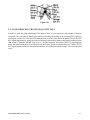
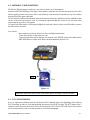
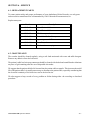
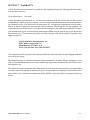
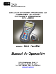
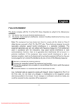
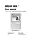
3 Channel Digital Ambulatory
ECG Holter Recorder
Model GBI-3SM
OPERATION MANUAL
2555 Collins Avenue, Suite C-5
Miami Beach, FL 33140, U.S.A.
Tel.: (305) 534-5905 Fax : (305) 534-8222
e-mail: [email protected]
TABLE OF CONTENTS
SECTION 1
1.1
1.2
Introduction
Introduction
GBI-3SM Specifications
SECTION 2
2.1
2.2
2.3
2.4
2.5
2.6
Holter Recorder Setup
Product Overview
Interactive Screens and Keys Description
Setting the Clock
Installing Batteries
Patient Cable Connection
Lead Wires ECG Channels Quality Test
SECTION 3
3.1
3.2
3.3
3.4
3.5
Operation
Patient Preparation
Patient Hook-up
Electrode Application
Electrode Placement Chart
Educating the Patient
SECTION 4
4.1
4.2
4.3
4.4
4.5
Recording Procedure
Step by Step Procedure
Memory Card Insertion
ECG Monitoring
Patient Event Button
Stopping the Recorder
SECTION 5
5.1
5.2
5.3
Late Potential Analysis (Optional)
Introduction
ECG signal acquisition
Procedure to record V.H.R.ECG
SECTION 6
6.1
6.2
Service
Replacement Parts
Maintenance
SECTION 7
Warranty
GALIX GBI-3SM Operation Manual
-2-
SECTION 1 - INTRODUCTION
1.1 - INTRODUCTION
Ambulatory electrocardiography is the continuous recording of a patient's electrocardiogram for a period of
24 hours (normally). The associated technology is referred to as a Holter system.
The recording is not really a form of continuous monitoring in the sense that the signal is not available
immediately. The recording is a representation of past events which permits a detailed analysis of them.
In a routine electrocardiogram, transitory changes may easily be missed due to the short time span over
which the recording is made. These intermittent episodes are more reliably detected when the
electrocardiogram is recorded continuously over a 24-hour period. This allows a correlation to be made
between patient activities and symptoms and transitory abnormalities of cardiac function which are
frequently associated with the tensions of daily life.
The Holter method consists of the continuous recording of more than 100,000 heartbeats in patients
undergoing their normal life. When the tape is analyzed, any cardiac arrhythmias which appear may then
be correlated with symptoms and events noted by the patient in his personal diary.
The patient is therefore instructed as to the enormous importance of his daily diary, in which he must note
his activities and the appearance of even the slightest symptoms. The patient is also informed of the
completely innocuous nature of the method in order to avoid apprehension on his part, which may generate
spurious changes not related to his normal electrocardiographic pattern.
The electrocardiography signal is commonly detected using disposable auto-adhesive electrodes which
assure good adhesion and electrode-skin continuity.
The GALIX GBI – 3SM unit is an ultra lightweight 3-Channel Digital ECG Holter Recorder using a SD
(Secure Digital) Card as ECG data storage media over a 24-48 or 72-hour period, and designed for
reliability in ambulatory ECG applications.
The collected information is downloaded, viewed, printed and analyzed using GALIX commercial analysis
program such as the WinTer Holter Analysis System. There are different sampling rates, amplitude
resolutions and record durations in accordance with the recording nature. No compression scheme is used,
thus allowing cleaner ECG signal waveforms.
CAUTION
Federal law restricts this device to sale by or on the
order of a physician
GALIX GBI-3SM Operation Manual
-3-
1.2 - GALIX GBI-3SM SPECIFICATIONS
DIMENSIONS
Length: 3" (76.2 mm), Width: 2.2" (55.88 mm), Height: 0.65"
(16.51 mm).
WEIGHT
Less than 2 ounces (55 grams) with battery.
ENCLOSURE
A.B.S., no metal parts exposed.
ADDITIONAL FEATURES
ECG Signals on LCD Screen, Real Time Clock, Digital Filtering
OPERATING
TEMPERATURE
0 - 70º C.
DIGITAL DISPLAY
Interactive 1.46in x 0.79in (37 x 20 mm) - 64x128dot graphic LCD.
CHANNELS
Three true ECG channels.
RECORDING METHOD
Digital. Ambulatory: 256 samples/sec - 20uV/step
V.H.R.ECG: 1,000 samples/sec - 0.5uV/step (for further
Ventricular Late Potential analysis)
STORAGE MEDIA
Standard SD (Secure Digital) memory card.
PATIENT CABLE
Super flexible and durable tinsel wire, seven lead cable.
RECORDING BANDWIDTH
.05 Hz - 100 Hz.
RECORDING DURATION
24-48-72 Hours ECG (Programmable).
EVENT MARKER
Tactile and audible feedback pushbutton.
POWER SUPPLY
1 standard AAA 1.5 Volts alkaline battery.
INPUT IMPEDANCE
>5 Mohms
CMRR
60 dB minimum.
STANDARD ACCESSORIES
One 3 lead patient cable, one 4 lead patient cable, one AAA 1.5V
alkaline battery, one SD card, one watertight dustproof shock resistant
case, one user's manual and hook-up accessories.
WARRANTY
18 months
GALIX GBI-3SM Operation Manual
-4-
SECTION 2 - HOLTER RECORDER SETUP
2.1 - PRODUCT OVERVIEW
Standard features of GALIX GBI-3SM Holter Recorder are shown on Figures 2.1a, 2.1b and 2.1c.
Front View
3 lead black
patient cable
connector
1.46”x0.79”
LCD display
Speaker
4 lead grey
patient cable
connector
Enter Key
Left Key
Right Key
Figure 2.1(a): Front View
Rear View
Plastic holders
for lanyards
Battery and
SD card
compartment
Figure 2.1(b): Rear View
Lateral View
Figure 2.1(c): Lateral View
GALIX GBI-3SM Operation Manual
-5-
2.2 - INTERACTIVE SCREENS AND KEYS DESCRIPTION:
The operation of the GALIX GBI-3SM Holter Recorder involves a simple sequential procedure
comprising: Patient Identification Entry, ECG signal quality Checking, Record Mode Setting, Date & Time
Checking or Setting, and Start Recording. The user interacts with the recorder through different LCD
screens and three push-buttons. The GALIX GBI-3SM offers 3 (three) language options: English, Spanish
and Portuguese.
There are:
• 2 (two) Recording Screens:
o Ambulatory
o V.H.R.ECG Recording
•
8 (eight) preparation screens:
o Patient Identification [ID]
o Channel 1 ECG [CH1]
o Channel 2 ECG [CH2]
o Channel 3 ECG [CH3]
o Recording Settings [Settings]
o Date & Time Setting [Date/Time]
o Start Recording [Start]
o Device Information [About]
The screen labels are positioned on top of the 64x128-pixels LCD, resembling MS Excel Sheets
All selections and modifications are performed using only three keys (◄ [Left], ► [Right], ● [Enter]). No
On-Off key is used to turn on/off the unit. Turn on is performed automatically once the battery is inserted
(1 AAA Alkaline battery). Turn off is performed through battery removal.
The selection of a particular Preparation Screen is performed by means of the [Left] and [Right] keys. After
selecting a particular Preparation Screen, data entry is enabled by pressing the [Enter] key. A question
mark will indicate that the operator can modify a parameter value or select a parameter option.
Ambulatory ECG Recording Screen
The information shown on the LCD during the recording of the ambulatory ECG is: Recording Type
(Holter 24-48-72-hour), Full Date, Current Time, Remaining Recording Time, Time of the Last Event (See
Figure 2.2).
Holter 24-hour
Date
TIME
Remaining Time
Last Event Time
Figure 2.2
By pressing any key a Patient Activated Event (PAE) is tagged on the recording. The last LCD line shows
the last time the PAE button was pressed. The GALIX GBI-3SM can record up to 250 events.
Information is presented Upside Up (See Figure 2.3a). When pressing the [Left] and [Right] keys
simultaneously, the information is presented Upside Down for 5 seconds to ease the reading by the user
(See Figure 2.3b).
GALIX GBI-3SM Operation Manual
-6-
Holter 24-hour
Tuesday
June 06, 2006
4:01:55 PM
Time remaining: 23:33:44
Last Event at: 3:58:47 PM
Figure 2.3a
Figure 2.3b
Recording cannot be stopped unless the battery or the memory card is removed. Prior to remove the
battery or the memory card it is recommended to press the [Right] and [Enter] key simultaneously. This
action will not stop the recording but will indicate the unit that the battery or card will be removed; the
message “Please, Remove the Memory Card or the Battery” will appear on the screen for 5 seconds.
Very High Resolution ECG Recording Screen
During the Very High Resolution ECG (V.H.R.ECG) recording process the information presented on
the LCD is: Recording Resolution (V.H.R.ECG-1000 samples/second), Full Date, Current Time,
Remaining Recording Time, “Press [Enter] to stop Recording” (See Figure 2.4).
V.H.R.ECG
Date
TIME
Remaining Time
Press to stop
●
Figure 2.4
The recording can be stopped by pressing the [Enter]
●
Key.
V.H.R.ECG
Tuesday June 06, 2006
4:01:55 PM
Time remaining: 9:25
Press to stop
●
Figure 2.5
GALIX GBI-3SM Operation Manual
-7-
Patient ID Screen
When no Patient ID has been entered, the initial Patient ID Screen looks as shown in Figure 2.6a. By
pressing the [Enter] key, a numeric data entry screen is accessed (see Figure 2.6b). The underscore
indicates the field (number or action) to activate.
In the Figure 2.6b, the underscore is pointing to the number 3. After pressing the [Enter] key this number,
will be copied onto the ID field at the left bottom of the LCD. It is possible to choose another number, such
as the one indicated in the Figure 2.6c (number 7). Again, by pressing the [Enter] key this number will be
copied onto the ID field.
The operator may decide to cancel the whole operation, to resume one position back withdrawing the
latest number entered or to confirm the whole ID entered. These operations are performed by placing the
cursor (underscore) on the words CANCEL, BACK or OK. After confirming the whole ID entered (OK
option) the screen will present the entered Patient ID on the center (see Figure 2.6d).
The selection of another Preparation Screen can only be performed from this screen.
ID
Patient ID:
None entered
Press
●
to select a Patient ID
Figure 2.6a
ID
0 1 2 3 4 5 6 7 8 9
Cancel Back OK
ID: 3
Figure 2.6b
ID
0 1 2 3 4 5 6 7 8 9
Cancel Back OK
ID: 37
Figure 2.6c
GALIX GBI-3SM Operation Manual
-8-
ID
Patient ID:
37
Press
●
to select a Patient ID
Figure 2.6d
Settings Screen
The Settings screen allows the modification of the recording parameters. The parameters are the
following: Mode, Record Time, Pacer Detector, Language, and LCD Contrast.
The Mode, Language and LCD Contrast are independent parameters. This means that the user may
select any of the available options independently. On the contrary, the Record Time parameter options
will depend on the selected mode. The Pacer Detector parameter is available only for Ambulatory
Recording.
The Mode options are: Ambulatory and V.H.R.ECG.
The Language options are: English, Español (Spanish) and Português (Portuguese).
The LCD Contrast values range from 10 to 90%, in 10% increments
The Pacer Detector parameter is only available in the Ambulatory Mode. There are two options: On
and Off.
The Record Time options are:
- Ambulatory Mode: 24-hour, 48-hour or 72-hour
- V.H.R.ECG Mode: up to 1 hour.
The minimum capacity of the Memory Card to use (SD - Secure Digital) will depend on the Sampling
Rate, Amplitude Resolution [step size and dynamic range] and Record Time. The Table 1 summarizes
this requirement.
When selected the Holter Mode, the LCD Screen will look as shown in the Figure 2.7. The default
parameters options are:
- Mode: Holter
- Record Time: 24 hr {24hr / 48hr / 72hr}
- Pacer Detector: Off
- Language: English {English, Español, Portuguès}
- Contrast: 60%
{10% to 90%}
When selected the V.H.R.ECG Mode, the LCD Screen will look as shown in the Figure 2.8. The
default parameter options are:
- Mode: High Resolution
- Record Time: 10 min {10min / 1hr / 24hr}
- Language: English {English, Español, Portuguès}
- Contrast: 60%
{10% to 90%}
GALIX GBI-3SM Operation Manual
-9-
Mode
Record
Time
(#1)
Sampling
ECG record
Minimum
Amplitude Resolution
Rate
length
Memory
Step
Dynamic
Bytes
[Hz] (#1) [uV] Range [mV] /Sa /Ch
[Bytes]
Capacity
(#1)
[MB] (#2,#3)
(#1)
256
20
+/- 2.55
1
66,355,200
64
256
20
+/- 2.55
1
132,710,400
128
256
20
+/- 2.55
1
199,065,600
192
1000
0.5
+/- 16.38
2
3,600,000
4
1000
0.5
+/- 16.38
2
21,600,000
24
Holter
24 hr
Holter
48 hr
Holter
72 hr
V.H.R.ECG 10 min
V.H.R.ECG
1 hr
Notes:
#1: ECG record length calculated as Recording Time*3*SamplingRate*Bytes/Sa/Ch
#2: The Memory card also contains patient demographic information, pacemaker detection information and
other study data.
#3: 1 Mega Byte is 220 Bytes or 1,048,576 Bytes
Table 1
Settings
Mode: Holter
Record Time: 24hr
Pacer Detector: Off
Language: English
Contrast: 60%
Press to change
●
Figure 2.7
Settings
Mode: High Resolution
Record Time: 1 hour
Language: English
Contrast: 60%
Press to change
Figure 2.8
●
The standard SD memory card delivered with the unit is 512 mega bytes.
GALIX GBI-3SM Operation Manual
- 10 -
2.3 – SETTING THE CLOCK
The GALIX GBI-3SM Holter Recorder has a Real Time Clock. The actual date and time can be adjusted
through the Date/Time Screen by means of the keyboard.
2.4 - INSTALLING BATTERY
The recommended battery for the GALIX GBI-3SM Holter recorder is a AAA 1.5V alkaline battery. For
proper battery placement first open the compartment pushing the door slightly in the sense of the arrows.
The correct polarity is noted at the bottom of the compartment.
Figure 2.9
NOTE: To insure reliable operation of the recorder, the battery must be replaced every patient recording.
2.5 PATIENT CABLE CONNECTION
There are two patient cables, a 3-lead connected to the black receptacle located on the upper right part of
the recorder and a 4-lead one connected to the grey receptacle located on the lower left (fig. 2.10 and 2.11)
3 lead – cables:
white – black - blue
4 lead – cables:
green – brown – red - orange
Figure 2.10
GALIX GBI-3SM Operation Manual
- 11 -
Figure 2.11
2.6 - LEAD WIRES ECG CHANNELS QUALITY TEST
In order to check the right functioning of the patient cable, it is not necessary to disconnect it from its
receptacle. The procedure is simple and consists of checking the quality of the incoming ECG signal by
viewing the screens CH1, CH2 and CH3 when the lead wires are connected to the patient. In case the CH1
ECG signal appears noisy, gently press the red and white electrodes to improve the contact with the patient
skin, or move / place the red and white wires to / in other locations. In case the CH2 ECG signal appears
noisy, the same actions have to be followed with the brown / black electrodes and wires. Finally, if CH3
ECG signal presents noise, the described actions have to be followed with the orange / blue electrodes and
wires.
GALIX GBI-3SM Operation Manual
- 12 -
SECTION 3 - OPERATION
3.1 - PATIENT PREPARATION
Materials needed:
1. Seven silver-silver chloride disposable electrodes designed for 24 hour Holter monitoring.
2. Prep pads.
3. Alcohol
Do not use 12-lead ECG or Stress Test electrodes. Use electrodes designed for long-term monitoring.
Proper patient preparation is the key for Holter recording.
3.2 - PATIENT HOOK-UP
In order to achieve a proper patient hook-up, the following steps are recommended:
1. Shave the electrode areas if needed. Wipe the skin in the electrode areas with alcohol prep pads.
2. Wipe the skin in the electrode areas with an alcohol prep pad again.
3. Dry the electrode application areas with a lint free cloth.
4. After preparing the electrode area, connect the electrodes to the ECG leadwires before applying the
electrodes to the patient.
5. Remove the backing from the pre-gelled disposable electrode, and place an electrode on each of the
seven prepared skin surface sites, carefully placing the gelled electrode firmly in contact with the skin
surface.
3.3 - ELECTRODE APPLICATION
Place the electrodes following the color code shown in the following figure:
Figure 3.1
Channel 1 = Red (+) - White (-)
Channel 2 = Brown (+) - Black (-)
Channel 3 = Orange (+) - Blue (-)
GALIX GBI-3SM Operation Manual
- 13 -
3.4 - ELECTRODE PLACEMENT CHART
Seven color coded leadwires are utilized for a true three channel ECG recording.
3-Channel electrode placement chart:
White
Red
Black
Brown
Blue
Orange
Green
Channel 1 (-). Place at the top/center of the sternum directly on the
right side of the bone.
Channel 1 (+). Place on the left side at the V5 position, on a rib.
Channel 2 (-). Place at the top of the sternum on the left side on the
bone.
Channel 2 (+). Place on the right side at the V1 position on a rib.
Channel 3 (-). Place at the top of the sternum below the black and
white leads on the bone.
Channel 3 (+). Place on the left side at the V3 position, on a rib.
Reference. Place on right side opposite V5 position on a rib.
3.5 - EDUCATING THE PATIENT
It has been said that one of the greatest advantages of ambulatory monitoring is that you do not have to be
with the patient constantly in order to collect diagnostic information. On the other hand, the disadvantages
of ambulatory monitoring are that you are not constantly with the patient while the data is being collected.
The moral of this story is that a successful procedure requires a properly educated patient. If the patient is
not instructed on what he can or cannot do during the procedure, the results will be totally dependent on
luck. Taking this into consideration, we have outlined the important points you should pass along to your
patients.
•
•
•
•
Do not get the GALIX GBI-3SM recorder wet! The recorder must be taken off by the doctor before the
patient can shower, take a bath, or swim. The patient would not be harmed if the recorder got wet, but
the machine could be severely damaged by any wet exposure.
Please do not pull or jerk the lead wires.
Avoid electric blankets.
In his diary, the patient should record the time, activity, and how he feels during abnormal episodes, in
addition to pressing the Event button. Every time the event button is pressed, a beep will sound as an
audible feedback.
GALIX GBI-3SM Operation Manual
- 14 -
SECTION 4 - RECORDING PROCEDURE
4.1 - STEP BY STEP PROCEDURE
Materials needed:
•
•
•
•
•
•
•
•
One SD (secure digital) memory card
One AAA 1.5V alkaline battery
Patient diary
GALIX GBI-3SM Holter recorder
Four-lead patient cable
Three-lead patient cable
Set of Lanyards
Seven pre-gelled Holter disposable electrodes.
In order to obtain a 24 hour - 3 channel continuous ECG recording, you have to follow the steps listed
below:
1- Insure the patient cables are connected to the GALIX GBI-3SM Digital Holter recorder (Figure 2.10).
2- Insert the SD card by pushing it gently into the recorder (Figure 4.1).
3- Install a new AAA 1.5V alkaline battery (see Figure 2.9). The LCD will show the introductory screens
and finally the Patient ID screen (Figure 2.6).
4- Enter the Patient ID number as explained in the Section 2.2.
5- Check the signal quality and amplitude of each channel accessing the CH1, CH2 or CH3 screen as
explained in the Section 2.2
6- Access the Recording Settings Screen to check the recording mode. Select the recording mode if
necessary.
7- The ambulatory ECG recording is ready to begin. Access the Starting Screen. Press <ENTER> to start
recording.
8- The LCD will show the Recording Screen indicating the recording mode, the actual time and a countdown timer. Once the recording has begun, any key of the keyboard can be used to mark Patient Events
9- Connect the lanyard or necklace to the recorder and hang it to the patient.
When the patient returns after a 24-hour period:
1. Press the <Right> and <ENTER> keys simultaneously to indicate that the memory card and/or the
battery will be removed. Remove the battery and the card from the recorder. The card is now ready to
be downloaded to the Holter Analyzer system.
2. Once the ECG download process has been completed in the Holter Analyzer, the memory card will be
available to begin a new 24-hour ambulatory ECG recording.
GALIX GBI-3SM Operation Manual
- 15 -
4.2 - MEMORY CARD INSERTION
SD (Secure Digital) memory cards are a tiny and versatile way of storing data.
Insertion of the SD: Holding by the edges, insert memory card into the recorder slot until you fell a click
(Do not apply pressure to the center of the card). Memory card can only be inserted one way; the chamfer
must be facing the upper right side.
The SD memory card has a mechanical write protection switch (lock), when this switch is enabled no data
can be written into the memory card. It is extremely important that this switch is not activated when
connecting the recorder to the patient.
To remove the SD memory card first push slightly the card and release it, then you will be able to remove
the SD from the recorder.
Precautions:
- Keep memory card away from heat, direct sunlight and moisture.
- To not bend, bend, or drop memory card.
- To prevent data loss and /or damage of a memory card, NEVER remove the card from the
GBI-3SM Holter recorder while data is being transferred (Section 4.5).
Lock
Figure 4.1
Important: Make sure the SD card is not locked before inserting it into the recorder.
4.3 – ECG MONITORING
It is very important to monitor each one of the three ECG channels prior to the beginning of the 24-hour
ECG recording, in order to verify the amplitude and quality of each ECG signal. The ECG signal of the 3
channels can be observed on the LCD screen by selecting the CH1, CH2 or CH3 tabs. There is no need to
use an external device such a cardiac monitor or an electrocardiograph.
GALIX GBI-3SM Operation Manual
- 16 -
4.4 - PATIENT EVENT BUTTON
Every time the patient wishes to note his activities or symptoms in his diary, he must gently press any key.
A beep will indicate that a Patient Activated Event was logged. If necessary, the corresponding time can be
taken from the LCD display.
4.5 - STOPPING THE RECORDER
When patient returns to the office the next day, press the <RIGHT> and <ENTER> keys to indicate the
recorder that the battery and/or memory card will be removed. A message on the screen will indicate that
they can be safely removed; this is a software protection tool in order to prevent data loss and/or damage to
the memory card witch could occur if the SD card is removed from the recorder while data is being
transferred. Remove the battery and the card. Next, remove the patient cable and electrodes.
In case you wish to stop the ECG recording before the 24-hour recording is completed, you must follow the
same procedure. The message allowing the memory card removal will last for 5 seconds. If the card and/or
battery are not removed, the equipment will continue the recording procedure until the 24-hour period has
elapsed.
GALIX GBI-3SM Operation Manual
- 17 -
SECTION 5 - LATE POTENTIAL ANALYSIS
5.1 - INTRODUCTION
According to the data estimated by the American Heart Association, Sudden Cardiac Death (SCD) is the
second leading cause of death in the United States after Cancer. In contrast to other terminal diseases, SCD
appears suddenly, causing death within an hour of the initial symptoms. Early detection in potential victims
is crucial in the treatment of these patients in order to prevent the SCD.
The micro potentials that appear at the end of the QRS complex represent the fragmented and delayed
conduction in damaged or diseased ventricular myocardium, and are indicators of possible ventricular
arrhythmia risks. Every pathological process that affects the conduction velocity in any ventricular tissue
area, may be studied by means of the Ventricular Late Potential analysis.
5.2 - ECG SIGNAL ACQUISITION
Conventional surface electrocardiography generally cannot detect late potentials. Its main limitation stems
from the inability to visualize the low amplitude signals, which may be as low as one microvolt.
Amplification of the standard electrocardiogram to detect late potentials results in contamination by
amplification of coincident electrical noise. Thus, sophisticated digital signal processing techniques have
evolved to detect individuals at risk for the development of sustained ventricular tachyarrhythmia, which
may cause marked haemodynamic embarrassment, including sudden death.
These techniques involve the recording, digitalization, averaging, amplification, and filtering of the ECG
signal, and enable the late potentials to be amplified, while eliminating undesired electrical signals.
The seven lead shielded patient wires are used to obtain three bipolar recordings. With these orthogonal
leads, the heart is viewed from three dimensional perpendicular aspects, referred to as x, y and z. The
electrode placement for this scheme is illustrated in Figure 5.1 and described in Table II on the following
page.
Figure 5.1
GALIX GBI-3SM Operation Manual
- 18 -
Lead
Color
Electrode placement
+X
Red
Left midaxillary line at the fourth intercostal space
-X
White
Right midaxillary line at the fourth intercostal space
+Y
Brown
Standard V3 position / proximal left leg
-Y
Black
Superior aspect of the manubrium
+Z
Orange
-Z
Blue
Immediately posterior to +Z position
Ref.
Green
Lower right rib
Standard V2 position
Table II
5.3 - PROCEDURE TO RECORD V.H.R.ECG
The steps to follow during the acquisition of V.H.R.ECG signals for LP analysis are the following:
1) Prepare the electrode sites and place the electrodes on the patient body as shown on Figure 5.1.
Remember that good electrode contact is critical to obtaining data with a minimum amount of noise.
2) Insert the SD card by pushing it gently into the recorder (Figure 4.1).
3) Install a new AAA 1.5V alkaline battery (see Figure 2.9). The LCD will show the introductory screens
and finally the Patient ID screen (Figure 2.6).
4) Enter the Patient ID number as explained in the Section 2.2.
5) Check the signal quality and amplitude of each channel accessing the CH1, CH2 or CH3 screen as
explained in the Section 2.2
6) Access the Recording Settings Screen to check the recording mode. Select the V.H.R.ECG recording
mode.
7) The V.H.R.ECG recording is ready to begin. Access the Recording Screen. Press <ENTER> to start
the recording.
8) The LCD will show the High Resolution Recording Screen indicating the recording mode, the actual
time and a count-down timer. Once the recording has begun, the keyboard can be used to reverse the
presentation or to stop the recording.
9) After the programmed V.H.R. Acquisition has elapsed, the unit will stop. Now, take out the memory
card and battery and continue with the procedure to perform the VLP analysis.
NOTE: In case you want to stop the ECG data acquisition before the programmed period, press the
<RIGHT> and <ENTER> keys simultaneously.
GALIX GBI-3SM Operation Manual
- 19 -
SECTION 6 – SERVICE
6.1 - REPLACEMENT PARTS
To ensure patient safety and proper performance of your Ambulatory Holter Recorder, use only parts
and accessories manufactured or recommended by GALIX Biomedical Instrumentation, Inc.
Replacement parts:
Part #
Description
15-03-001
4-lead Patient Cable
15-03-002
3-lead Patient Cable
15-04-001
SD Memory card
15-04-002
One AAA Alkaline Battery
15-04-003
Operating manual CD
15-04-004
Set of lanyards
15-04-005
Shock resistant carrying case
6.2 - MAINTENANCE
The recorder should be cleaned regularly, using a soft cloth moistened with water and mild detergent.
Remove any adhesive from the lead wires.
The patient's cable lead wire snap connectors should be cleaned with alcohol and a small brush to eliminate
any trace of gel remaining after the use of disposable electrodes.
We suggest that the patient cable be left inserted into the patient cable receptacle. This increases the useful
life of the patient cable. It is usually unnecessary to disconnect the patient cable, especially considering that
the electrical continuity of the lead wires can be checked in situ.
We also suggest to keep records of every problem or failure during either the recording or download
procedure.
GALIX GBI-3SM Operation Manual
- 20 -
SECTION 7 - WARRANTY
GALIX Biomedical Instrumentation, Inc. provides to the original purchaser the following limited warranty
from the date of invoice.
All serialized parts:
18 months
GALIX Biomedical Instrumentation, Inc. warrants each instrument to be free from defects in material and
workmanship. Liability under this warranty covers servicing of the instrument when returned prepaid from
the customer's facility. GALIX Biomedical Instrumentation, Inc. will repair any component(s) or part(s) that it
find to be defective during the period of this limited warranty. Should a defect become apparent, the
original purchaser shall first notify GALIX Biomedical Instrumentation, Inc. of the suspected defect. To return
your instrument for repair, a return material authorization (RMA) must be provided by GALIX Biomedical
Instrumentation, Inc. The instrument should be carefully packaged with receipt as proof of purchase and
shipped prepaid to:
GALIX Biomedical Instrumentation, Inc.
2555 Collins Avenue Suite C-5
Miami Beach, FL 33140, U.S.A.
Phone: (305) 534-5905 Fax: (305) 534-8222
Your instrument will be repaired in the shortest possible time and returned by the same shipping method as
received by the factory.
This limited warranty is void if the instrument has been damaged by Accident, Misuse, Negligence, Act of
God, or if the instrument has been serviced or modified by any person not authorized by GALIX Biomedical
Instrumentation, Inc.
This limited warranty contains the entire obligation of GALIX Biomedical Instrumentation, Inc. and no other
warranties expressed, implied, or statutory are given. No representative or employee of GALIX Biomedical
Instrumentation, Inc. is authorized to assume any further liability or grant any further warranties except as set
herein.
GALIX GBI-3SM Operation Manual
- 21 -