1
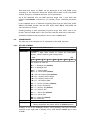
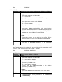
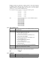
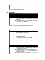
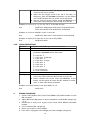
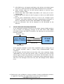
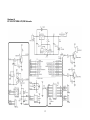
Smart Peripheral Controller
Low Cost Serial
LCD/OLED
Trademarks & Copyright
AT, IBM, and PC are trademarks of International Business Machines Corp.
Pentium is a registered trademark of Intel Corporation.
Hyper Terminal is copyright by Hilgraeve Inc.
CodeVisionAVR is copyright by Pavel Haiduc, HP InfoTech s.r.l.
Table of Contents
1
Introduction...............................................................................................
1.1.
Specification................................................................................................
1.2.
SPC LOW COST SERIAL LCD/OLED Variant DDRAM Address........
1.3.
Suggested System......................................................................................
3
3
3
3
2
Hardware..................................................................................................
2.1.
Component Layout.....................................................................................
2.2.
Connector and Jumper Settings..............................................................
4
4
4
3
Interface....................................................................................................
3.1
UART Interface............................................................................................
3.2
Command Set..............................................................................................
3.2.1 Set LCD Control..........................................................................................
3.2.2 Locate...........................................................................................................
3.2.3 Write Data..................................................................................................
3.2.4 Read Address/Data..................................................................................
3.2.5 Clear LCD....................................................................................................
3.2.6 Change Line.................................................................................................
3.2.7 Text Slot.......................................................................................................
3.2.8 LCD/Buzzer Setting...................................................................................
5
5
6
6
7
7
8
8
9
9
10
4
Testing Procedure.....................................................................................
10
5
Application and Program Examples.........................................................
11
Attachment
A.
SPC LOW COST SERIAL LCD/OLED Schematics.................................
2
12
1.
INTRODUCTION
Smart Peripheral Controller (SPC) LOW COST SERIAL LCD is a CHARACTER
LCD/OLED controller module that supports UART interface level TTL and RS232 line so that it can save and ease the cable works. Application examples
from SPC LOW COST SERIAL LCD/OLED are character monitor, display,
counter display, time display, etc.
1.1
SPECIFICATION
SPC LOW COST SERIAL LCD/OLED specification are as follows:
• Requires power supply: 6.5 – 12 Volts.
• Equipped with 3.3 Volts or 5 Volts voltage regulator.
• Equipped with UART TTL or RS-232 level.
• Equipped with buzzer that can be controlled via UART
• Turning backlight on/off via UART.
• Compatible with up to 40x2 LCD Module that uses a HD44780 compatible
driver.
• Compatible with OLED module display.
• LCD/OLED variants supported by SPC LOW COST SERIAL LCD/OLED:
- LCD 8 x 2 , without backlight
- LCD 16 x 2 , with backlight
- LCD 20 x 2 , with backlight
- LCD 20 x 2 Large , with backlight
- LCD 20 x 4 , with backlight
- LCD 24 x 2 , with backlight
- LCD 40 x 2 , with backlight
1.2
SPC LOW COST SERIAL LCD/OLED VARIANT DDRAM ADDRESS
8x2
00H………….07H
40H………….47H
16 x 2
………0FH
………4FH
20 x 2
………13H
………53H
24 x 2
………17H
………57H
40 x 2
………27H
………67H
20 x 4
00H………….………………………………13H
40H………….………………………………53H
14H………….………………………………27H
54H………….………………………………67H
1.3.
SUGGESTED SYSTEM
Suggested system for SPC LOW COST SERIAL LCD/OLED:
Hardware:
• PC™ AT™ Pentium® IBM™ Compatible.
• DVD-ROM Drive and Hard disk.
Software:
• The files found in the CD/DVD program:
Datasheet, contoh_uart.c, and SPC LOW COST SERIAL LCD/OLED Manual.
3
2.
HARDWARE
2.1.
COMPONENT LAYOUT
2.2.
CONNECTOR AND JUMPER SETTINGS
VIN (J1) connector is a connector for module power supply. Power supply input
will be connected with voltage regulator.
Connector
Pin
Name
Function
1
GND
Ground reference for power supply input
2 6.5-12VDC Connected to power supply (6.5 – 12 VDC)
J1
REG SLCT (J2) jumper is used to select the output voltage from the voltage
regulator on the SPC LOW COST SERIAL LCD/OLED.
REG SLCT (J2) Jumper
Output Voltage Value
3.3 VDC
(jumper attached)
5 VDC
(jumper released)
LED PWR (D4) is the power supply input LED indicator.
Variable Resistor R16 can be turned to adjust the LCD contrast.
UART RS232 (J4) RJ11 connector is a connector for UART RS-232 Interface.
Pin
2
3
4
5
Name
NC
COM
TX
RX
Function
Not connected
Ground reference
Data output line
Data input line
J4 Front view
5 4 3 2
RX GND
TX
4
UART TTL (J8) connector is a connector for UART TTL Interface.
Pin
1
2
3
Name
GND
TX-TTL
RX-TTL
Function
Ground reference
Data output line
Data input line
RX-JMP (J6) and TX-JMP (J7) jumpers are used to select UART interface
voltage level used by SPC LOW COST SERIAL LCD/OLED.
RX-JMP and TX-JMP jumpers
UART Level Voltage
3 2 1
J7
J6
UART TTL
3 2 1
J7
J6
UART RS-232
LCD PORT (J5) connector a connector to connect SPC module with LCD/OLED
module.
Pin
1
2
3
4
5
6
7
8
9
10
11
12
13
14
15
16
Name
DGND
VCC
VR
RS
R/W
E
D0
D1
D2
D3
D4
D5
D6
D7
VCC
BLK
Function
Ground reference
Output voltage (3.3V or 5V) for LCD/OLED module
LCD contrast adjuster
Register Select
Read/Write Selector
Start data read/write
Data pin 0
Data pin 1
Data pin 2
Data pin 3
Data pin 4
Data pin 5
Data pin 6
Data pin 7
Output voltage (3.3V or 5V) for LCD backlight
Ground reference for LCD backlight
3.
INTERFACE
SPC LOW COST SERIAL LCD/OLED has the UART TTL and UART RS232
interfaces which can be used to receive or send data.
3.1.
UART Interface
UART communication parameters are as follows:
• 38400 bps
• No parity bit
• 8 bit data
• No flow control
• 1 stop bit
5
Each data that enters via UART will be displayed on the LCD/OLED screen
according to the Character Generator ROM pattern table on the LCD/OLED
manual, except for command character and its parameters.
All of the command sent via UART interface begin with 1 byte data that
contains <command>, followed by (if needed) n-byte command parameter
data.
If the command sent is a command requesting data from the SPC LOW COST
SERIAL LCD/OLED module, then the SPC LOW COST SERIAL LCD/OLED will
send the data via TX line.
Sending/reading a data parameter/response larger than 255 is sent in two
phases. One byte MSB data is sent/read first and then followed by LSB data.
Available commands and parameters can be seen in section 3.2.
3.2.
COMMAND SET
The following is the complete list of commands on the UART Interface.
3.2.1. SET LCD CONTROL
Function
Control the LCD/OLED function
Command
0x08
Parameter
< control >
contains 1 byte data control to control the LCD/OLED
display, with the following bits configuration:
MSB
BL
LSB
D/C
L
R
Dir
Dis
Cur
Blk
The function of each bit:
BL = 1 : Backlight On (default)
BL = 0 : Backlight Off
D/C = 1 : Display Shift
D/C = 0 : Cursor Shift (default)
L R = 00 : No Display Shift (default)
L R = 01 : Display Shift to Right
L R = 10 : Display Shift to Left
L R = 11 : No Display Shift
Dir = 1 : Cursor Increment (default)
Dir = 0 : Cursor Decrement
Dis = 1 : Display On (default)
Dis = 0 : Display Off
Cur = 1 : Cursor On (default)
Cur = 0 : Cursor Off
Response
Description
Blk = 1 : Blink On (default)
Blk = 0 : Blink Off
● When the SPC module is turned on, reset, or after the LCD
Setting command, the control will be on default position.
Example to turn on the backlight, display, cursor, blinking, and cursor increment
direction (to the right) and no display/cursor shift, then the control has a value
of 0x8F.
6
User
:
3.2.2. LOCATE
Function
Command
Parameter
0x08 0x8F
Adjusts the cursor position on the screen, DDRAM, or CGRAM
0x09
< type >
parameter type can be filled with:
1 = Locate LCD
(to adjust cursor position on the LCD/OLED screen)
2 = Locate DDRAM
(to adjust cursor position on the DDRAM)
3 = Locate CGRAM
(to adjust cursor position on the CGRAM)
< column >
parameter column can be filled with desired column
position (the leftmost position is the 0th column) for Locate
LCD or can be filled with desired DDRAM/CGRAM
address for Locate DDRAM/Locate CGRAM
< line >
parameter line can be filled with desired line position (the
uppermost position are the 0th line) for Locate LCD or
must be filled with 0 for Locate DDRAM/Locate CGRAM
● To find the allowed DDRAM and CGRAM addresses, can
be seen in HD44780 datasheet or the LCD/OLED
datasheet.
Response
Description
Example to adjust the cursor position so that it is on the 5th column and 0th line,
then after the Locate LCD command is sent, it is followed by column data with a
value of "0x05" and line data with a value of "0x00".
User
3.2.3. WRITE DATA
Function
Command
Parameter
:
0x09 0x01 0x05 0x00
Writes data to DDRAM or CGRAM
0x0A
< type >
parameter type can be filled with:
1 = Write Data to DDRAM
(writes data into DDRAM according to the address
pointed by DDRAM cursor)
2 = Write Data to CGRAM
(writes data into CGRAM according to the address
pointed by CGRAM cursor)
Response
Description
< data >
parameter data can be filled with 1 byte written data
● After
the command is performed, then the
DDRAM/CGRAM cursor position will be incremented
automatically.
7
Example to make a new character, a degree symbol (°), and will be accessed
via DDRAM address 0x00, then the first thing to do is to perform LOCATE
CGRAM command to the 0x00 address. The next step is to save the degree
symbol icon (°) on the specified CGRAM memory.
For example the degree symbol (°) is made by the following data:
00000000
00001111
00001001
00001001
00001111
00000000
00000000
00000000
User
:
=
=
=
=
=
=
=
=
0x00
0x0F
0x09
0x09
0x0F
0x00
0x00
0x00
0x09 0x03 0x00 0x00 // Locate CGRAM command
0x0A 0x02 0x00
0x0A 0x02 0x0F
0x0A 0x02 0x09
0x0A 0x02 0x09
0x0A 0x02 0x0F
0x0A 0x02 0x00
0x0A 0x02 0x00
0x0A 0x02 0x00
3.2.4. READ ADDRESS/DATA
Function
Reads the data/address on the DDRAM/CGRAM, reads the
LCD/OLED type
Command
0x0B
Parameter
< type >
parameter type can be filled with:
1 = Read data from DDRAM
(to read the data pointed by the DDRAM cursor)
2 = Read data from CGRAM
(to read the data pointed by the CGRAM cursor)
3 = Read DDRAM address
(to read the DDRAM cursor address)
4 = Read CGRAM address
(to read the CGRAM cursor address)
5 = Read LCD type
(to read the LCD/OLED type saved in the EEPROM)
< result >
contains the requested data or address
-
Response
Description
Example to find the DDRAM address of the current cursor position.
User
SPC
3.2.5. CLEAR LCD
Function
Command
Parameter
:
:
0x0B 0x01
< result >
Clears the LCD/OLED screen display
0x0C
8
Response
Description
●
When this command is sent, then the LCD/OLED display
will be cleared and DDRAM cursor will return to 0x00
position.
For example, clearing LCD/OLED display.
User
:
3.2.6. CHANGE LINE
Function
Command
Parameter
Response
Description
0x0C
Changes cursor line
0x0D
● When this command is sent, then the LCD/OLED cursor will
move to the next line and column position will be in the
0th column.
● If the cursor is already on the bottommost line then the
cursor will return to the 0th line.
● Make sure that the LCD/OLED type had been set to
match the LCD/OLED used so that this command can
function correctly.
Example to change the LCD/OLED cursor position to the next line.
User
3.2.7. TEXT SLOT
Function
Command
Parameter
:
0x0D
Save/display a series of text
0x0E
< type >
parameter type can be filled with:
1 = Write data to slot
(to save text on the slot)
2 = Read data from slot
(to display the saved text on the LCD/OLED)
< slotNum >
parameter slotNum can be filled with byte data with a
value of 0 up to 7 according to the number of the desired
text slot
Response
Description
< textData >
parameter textData contains the saved text data
● Parameter textData is needed for "write data to slot"
command. Whilst for "Read data from slot" command is
not needed/must not be sent.
● A maximum of 8 text slots, each is able to store up to 16
characters, except for the 7th slot that has a 15
characters text length.
● For the 7th text slot, the 16th character is always filled
with a space character.
9
●
●
●
The "Read data from slot" will display the texts starting
on the current cursor position.
When the text length saved in the slot is less than 16
characters, then the text data parameter can be added
with "0x0E" (decimal unit 14) as the end of text mark.
The text saved in the slot will be saved into EEPROM so it
will not be erased when the SPC module is turned off.
Example to save text "0 1 2 3 4 5 6 7 8 9" on the 0th text slot.
User
:
0x0E 0x01 0x00 0x30 0x20 0x31 0x20 0x32 0x20
0x33 0x34 0x35 0x36 0x20 0x37 0x38 0x39
Example to save text “ABCDE“ on the 1st text slot.
User
:
0x0E 0x01 0x01 0x41 0x42 0x43 0x44 0x45 0x0E
Example to display text from the 1st text slot to LCD/OLED.
User
:
0x0E 0x02 0x01
3.2.8. LCD/BUZZER SETTING
Function
Determines LCD/OLED type and controls buzzer
Command
0x0F
Parameter
< command >
parameter command can be filled with:
0 = LCD 8 x 2
1 = LCD 16 x 2 (default)
2 = LCD 20 x 2
3 = LCD 20 x 2 Large
4 = LCD 20 x 4
5 = LCD 24 x 2
6 = LCD 40 x 2
7 = turns on buzzer
8 = turns off buzzer
Response
Description
●
●
LCD/OLED type selection will be saved into EEPROM so it
will not be erased when the SPC module is turned off.
Buzzer selection will not be saved into EEPROM, so the
buzzer will be turned off when the SPC module is turned,
reset, or after LCD Setting command.
Example to set SPC module to use LCD/OLED 16 x 2.
User
4.
:
0x3F 0x01
TESTING PROCEDURE
1. Connect LCD/OLED to SPC LOW COST SERIAL LCD/OLED module via LCD
(J5) connector.
2. Adjust REG SLCT (J2) jumper so that it matched the LCD/OLED voltage (3,3
/ 5 V).
3. Connect the 9 Volt power supply to SPC LOW COST SERIAL LCD/OLED
module.
4. Power indicator LED will light up.
5. Buzzer will sound for about 200ms.
6. If the LCD is equipped with backlight, then the backlight will light up.
10
7. LCD/OLED cursor will appear and blink on the 0th line and column (upper
left corner) which marks that the LCD/OLED initialization has succeeded.
8. When needed, adjust the VR LCD contrast adjuster so that the cursor
display is clearly visible.
9. Connect SPC LOW COST SERIAL LCD/OLED to PC serial port via RJ11
connector (J4).
10. Set RX-JMP and TX-JMP (J6 and J7) jumpers so that it uses UART RS-232
level.
11. Run the serial communication software on the PC (for example: Hyper
Terminal©) and adjust baudrate and other communication parameters so
that it is compatible with SPC LOW COST SERIAL LCD/OLED module.
12. Type the characters that will be displayed on the LCD/OLED via the
software.
5.
APPLICATION AND PROGRAM EXAMPLES
As an application example, DT-AVR Low Cost Micro System (LCMS) module is
used as master for displaying message on the SPC LOW COST SERIAL
LCD/OLED module with UART TTL interface. The following are the connections
between modules:
VIN (6,5V – 12V)
SPC LOW COST
SERIAL LCD/OLED
TXTTL
RX (PORTD.0)
RXTTL
TX (PORTD.1)
DT-AVR
LCMS
COM (Ground)
GND (Ground)
As the program example as in the above application, there is contoh_uart.c in
the included CD/DVD which is written using CodeVisionAVR© 2.03.9
evaluation.
In the program, DT-AVR LCMS will send Clear LCD screen command, display
"WELCOME" text, and sound the buzzer. After 2 seconds, the screen will be
cleared again, Locate LCD command is sent before DT-AVR LCMS writes the
message "Innovative" and "Electronics" consecutively while sounding the buzzer.
After all of the messages have been sent, then the backlight will be blinked
twice.
♦ Thank you for your confidence in using our products, if there are difficulties, questions,
or suggestions regarding this product please contact our technical support:
[email protected]
11
Attachment A.
SPC LOW COST SERIAL LCD/OLED Schematics
12