1
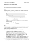
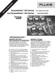
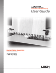
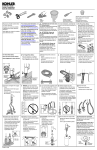
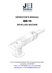
User manual
mini
INITIAL SETTING UP OF YOUR
1
Contents of parts required to assemble and operate the mini
D
LEFT DISC
2x A
1x
Round tubes
Double square tube
2x
C
1x
CHARGER
C
B
Pre assembled disc Assembly
Plastic headed wing nuts
1x
A
1x
Round tubes with square socket
2x C
RIGHT DISC
Step 1:
Insert the 2 round tubes (A) fully into the
chassis tube (B) and secure with the wing
nuts (C) already fitted. Slide the handle
bar assembly (D) onto the round tubes to
the required working height, and secure
with the 2 wing nuts supplied.
1x
Pre assembled sprayhead assembly
FITTING THE DISC AND SPRAY HEAD ASSEMBLIES TO THE MACHINE
1. SIDE FIXING: (fig 1)
To fix the disc assembly for side spraying at the rear wheels of the machine, slide the long square section tube into the
larger tube underneath the machine, between the front and rear wheels. Before securing, slide the disc assembly onto the
square section tube and secure with the wing nut on the front of the assembly (1). Adjust the long tube until the discs
assembly is in the correct position for the spraying operation, ensuring that the right disc is set at least 25mm past the
outside edge of the rear wheel, to avoid the wheel running over the sprayed line. To spray from the right side of the
machine simply slide the square tube into the larger tube under the machine from the right side and repeat the operation,
ensuring that the securing wing nut (1) faces the front. To spray from the side at the front of the machine, slide the long
tube into the square section sockets at the front of the machine between the front wheels (2) When the disc assembly has
been fitted in the desired position. Fit the sprayhead onto the upright square tube between the discs, and secure with
the wing nut. The spray head should face the back of the machine when in the correct position.
fig. 1
LEFT DISC
RIGHT DISC
FRONT OF
MACHINE
25mm
1
2
2
1. FRONT CENTRE FIXING: (fig. 2)
To fix the disc assembly for spraying from the centre front of the machine, loosen the wing nut (3) securing ONE round tube
with the square section socket at the front of the machine (2) and pull forwards approx 200mm. Slide the disc assembly
tube into the socket sufficient to allow the second tube (2) to be pulled forward to a position where the disc assembly tube
can be fitted into the other square socket. Position the disc assembly so that the sprayhead post (4) is central between
the sockets. Secure the tubes (2) with the wing nuts (3) and set the disc width using the wing nuts (5) ensuring that the
discs are an equal distance from the spray head post. When the disc assembly has been fitted in the desired position
fit the sprayhead as described above.
The machine is designed to
allow 5 different positions
for the sprayhead as shown
fig. 2
4
5
4
1
3
2
3
5
2
The IGO mini is manufactured in the UK by: Linemark (UK) Ltd, Rossendale, BB4 6JB.
Page 1
© copyright 2014 Linemark (UK) Ltd all rights reserved
Distribution:
E. Marker A/S
Okslundvej 8, Bov
DK-6330 Padborg
Tel.: +45 74 67 08 08
E-mail: [email protected]
www.emarker.dk
www.emarker.dk
User manual
GETTING STARTED: PRIMING - SPRAYING - CLEANING
PRIMING THE PUMP:
Before attempting to spray paint for the first time, the pump will need to be primed.
To avoid any wastage of paint, it is recommended that this is done using water.
To prime, first pour clean cold water into the 5ltr container supplied with the machine, next insert
the feed probe (a) fig. 3, into the container and secure with the cap (b).
Turn the control valve (c) fig. 4, to the UP position, open the prime tube tap (d) fig. 4, and turn on
the machine using the switch on the handlebar.
As soon as water starts to flow freely from the tap, turn off the machine and then close the tap.
(Do not close the tap with the machine running)
fig. 3
SPRAYING WITH PAINT:
Once primed, Remove the probe from the water container, and insert into the paint container.
Turn the control valve to the DOWN position, which will direct the flow to the spray nozzle and
switch the machine on. Initially water will start to spray through the nozzle, followed by paint.
You will now be ready to start the marking / striping operation.
At any time during the marking / striping operation the paint flow can be stopped and
fig. 4
restarted, using the switch on the handlebar.
Paint tube valve
b
Bottle cap
a Feed probe
d
prime tube
tap
CLEANING THE MACHINE: ( CLEAN THE MACHINE IN A SUITABLE AREA TO AVOID DAMAGE)
To Prime / clean
At the end of each spraying day, it is important that the machine is flushed through with
clean water to ensure that the nozzles, filters, pipes and pump are cleaned of paint. To do
Turn UP
this, first make sure that machine is turned off, and the control valve is in the off position, as
to prime
shown in fig. 4. Remove the probe from the paint container, being careful not to allow the
OFF position
c
paint to drip from the probe onto any surfaces that may be damaged. Open the prime tube
from pump
tap (d) place the paint container in a position where the tap can discharge the paint into
Turn DOWN
to spray
the container, and turn the control valve into the UP position and turn on.
This will allow the paint in the pipes and pump to be returned to the paint container
avoiding as little paint wastage as possible. When all the paint has been discharged, turn the
machine off. Insert the probe into the water container and switch the machine back on. This
will flush water through the probe, pipework and the pump, when the water runs clear
Nozzle
or a weak, milky colour, turn off the machine and close the prime valve tap. Turn the control
valve to the DOWN position and turn the machine back on to flush water through the spray
head and nozzles. When the operation is complete, turn off the machine. Any water in the system will be expelled as part
of the start of day priming operation. If paint is used to prime the machine, discharge the paint into a suitable container to
avoid wastage.
CHARGING THE BATTERY
fig. 5
To ensure optimum performance from the battery, it should be charged at the end
of each spraying day.
To charge the battery, on or off, the machine:
Disconnect the battery lead socket s2 from the control box plug p1 by depressing
the clip on the side of the plug and pulling apart.
CONTROL
BOX
p1
BATTERY
s2
p2
CHARGER
Clip
Connect the charger plug p2 to the battery socket s2 The socket and plug will only connect one
way and should not try be forced. Forcing them in an incorrect manner will cause damage to the
electrical components
Connect the charger to the mains supply and switch on, charging will now start.
During the initial bulk charge the battery indicator light will show BLUE. After the initial charge
the indicator light will change to RED to show that the charger is in ‘floating’ or ‘trickle’ charge
mode. Ideally the battery should be charged overnight to ensure a complete charge cycle.
The charger is designed so that it can be safely left on overnight
AS WITH ALL ELECTRICAL EQUIPMENT, DO NOT EXPOSE THE CHARGER TO WET
OR EXTREMELY DAMP CONDITIONS.
Page 2
© copyright 2014 Linemark (UK) Ltd all rights reserved
Distribution:
E. Marker A/S
Okslundvej 8, Bov
DK-6330 Padborg
Tel.: +45 74 67 08 08
E-mail: [email protected]
www.emarker.dk
www.emarker.dk