1
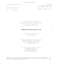
Last Updated: 13-April-2009 TB-980502B Technical Bulletin, Communicating with TM Honeywell SMV3000 Multivariable Transmitters OMNI FLOW COMPUTERS, INC. 12620 West Airport Boulevard, Suite 100 Sugar Land, Texas 77478 United States of America Phone-281.240.6161 Fax: 281.240.6162 www.omniflow.com 52-0003-0003/Rev B Page 1 of 12 TB-980502B Communicating with HoneywellTM SMV 3000 Multivariable Transmitters NOTE: User Manual Reference - This Technical Bulletin complements the information contained in the User Manual, and is applicable to all firmware revisions .74+. Communication with HoneywellTM SMN3000 Smart Transmitters – This feature allows you to communicate with Honeywell SMV3000 Smart Multivariable Transmitters which provide Differential Pressure, Temperature and Static Pressure, via OMNI’s HV type Process I/O Combo Modules and using Honeywell’s DE Protocol. Table of Contents Scope ............................................................................................................................................3 Abstract .........................................................................................................................................3 DE Protocol Overview ...................................................................................................................3 Transmitter Database....................................................................................................................3 The Honeywell™ Handheld Communicator ..................................................................................3 Combo Module LED Status Indicators ..........................................................................................4 Switching Between Analog and Digital Mode................................................................................4 Viewing the Status of the Honeywell Transmitter from the Keypad ..............................................4 Viewing the Status of the Honeywell™ Transmitter from the Keypad...........................................5 Obtaining More Detailed Status Information from the Keypad ......................................................7 Transducer Alarms Logged by the Flow Computer.......................................................................9 HV Combo Module Address Jumpers .........................................................................................10 How the I/O Points are Assigned ................................................................................................10 OMNICOM Revision....................................................................................................................11 Figures Figure 1. Setting the Address Jumpers of the HV Combo Module.............................................10 52-0003-0003/Rev B Page 2 of 12 Communicating with HoneywellTM SMV 3000 Multivariable Transmitters TB-980502B Scope All OMNI 6000/OMNI 3000 Flow Computers containing firmware 21.74+, 23.74+, 27.74+ are able to communicate with Honeywell™ SMV3000 Smart Multivariable Transmitters. This feature uses Honeywell’s DE Protocol and requires that an HV Combo I/O Module be installed in your flow computer. Abstract Using an ‘HV’ Combo I/O Module, the OMNI Flow Computer can communicate with up to four (4) Honeywell™ SMV3000 Smart Multivariable transmitters. These transmitters provide Differential Pressure, Temperature and Pressure signals using Honeywell’s DE Protocol. Only one (1) ‘HV’ Type Combo Module can be installed in the flow computer. Loop power is provided by the ‘HV’ combo module. DE Protocol Overview Digital data is transmitted serially between the flow computer and Honeywell Smart Transmitters by modulating the current in the two wire loop connecting the devices. Power for the transmitter is also taken from this current loop. Data is transmitted at 218.47 bits per second with a digital ‘0’ = 20 mA and a digital ‘1’ = 4 mA. In normal operation, the Honeywell transmitter operates in the ‘6-byte Burst Mode’. In this mode, the transmitter transmits the following data to the flow computer every 366 msec: Byte #1 Byte #2-#4 Byte #5 Byte #6 Status Flags Process Variables % Span Value (3-byte floating point) Database ID (indicates where in the transmitter database Byte #6 belongs) Database Data Value Transmitter Database By using the data contained in Bytes #5 and #6, the flow computer builds and maintains an exact copy of the multivariable transmitter’s configuration database. The transmitter database, which is sent to the OMNI Flow Computer, is about 132 bytes. Based on the burst rate of the transmitter it can take about forty-five (45) to fifty-five (55) seconds to completely build a copy of the transmitter database within the flow computer. The transmitter database is continuously compared against the flow computer configuration settings for that transmitter. The flow computer automatically corrects any differences between the databases by writing the correct configuration data to the transmitter. The Honeywell™ Handheld Communicator The flow computer is responsible for configuring the following entries within the transmitter: Lower Range Value or Zero Transmitter Span or Max Range Damping Factor Tag Name DP, SP and Temperature conformance bits Any changes made to 1, 2, 3 and 5 using the handheld communicator will be overwritten by the flow computer. In the digital mode it is not absolutely necessary to calibrate the transmitter’s outputs using the handheld communicator. The user can however trim the transmitter’s output calibration using the handheld communicator if he so desires, without interference from the flow computer (refer to Honeywell documentation for details of trimming corrects). Whether the transmitter is trimmed with the handheld or not, the digital signals should be final calibrated ‘end to end’ using the normal analog input method described in Chapter 8 of Volume 1 of the User Manual. 52-0003-0003/Rev B Page 3 of 12 Communicating with HoneywellTM SMV 3000 Multivariable Transmitters TB-980502B Combo Module LED Status Indicators Each I/O channel of the ‘HV’ Combo module has a set of two (2) LED indicators, one (1) green and one (1) red. The green LED shows all communication activity taking place on the channel (flow computer, transmitter and handheld communicator if connected). The Red LED lights only when the flow computer is transmitting data to the transmitter. Normal digital operation is indicated by a regular pulsation of the green LED (about three (3) pulses per second). The red LED will be seen to blink whenever a configuration change is made in the flow computer which affects that particular transmitter. Switching Between Analog and Digital Mode Connecting an analog mode Honeywell multivariable transmitter to the flow computer will cause it to automatically switch the transmitter to the digital DE mode sending out a series of “Wake up” commands to the Honeywell transmitter. A switch over to the digital mode by the transmitter will cause the green LED on the combo module to pulse steadily indicating that communications have been established. To disable the wake up command and initialize communications between the Honeywell transmitter and the flow computer, delete all I/O point assignments within the flow computer to that I/O point. Using the Honeywell handheld communicator press [Shift] [A/D] and wait until the handheld displays ‘Change to Analog?’ Answer by pressing [Enter] (Yes). ‘SFC Working’ will be displayed. The green LED on the ‘HV’ Combo module on that channel will stop pulsing. Reentering the I/O point will cause the OMNI to send the wake up command to the Honeywell and after three (3) commands sends the green LED on the Honeywell module will pulse at a steady 3Hz rate. Viewing the Status of the Honeywell Transmitter from the Keypad To verify the data being received from the smart transmitter, press [Input] [Status] and [Enter] from the front panel. The following data displays: HV‐1 Transmitter DB Status OK Gstatus NON‐CRITICAL DP% 25.00 SP% 76.50 TT% 32.13 DP LRV 0.0 DP Span 400.0 DP Damp Secs. .16 DP Conformity bit 0 SP LRV 406.8 SP Span 27680.2 SP Damp Secs .16 SP Conformity bit 0 TT LRV .0 TT Span 100.0 TT Damp Secs .3 TT Conformity bit 0 SW Revision 2.1 Serial # xxxxxxxxxx DP Range 400.0 SP Range 20760.5 TT Range 850.0 ID/TAG SMV‐3000 Filter Hertz 60 SensorType RTD‐PT100 52-0003-0003/Rev B Page 4 of 12 Communicating with HoneywellTM SMV 3000 Multivariable Transmitters TB-980502B Viewing the Status of the Honeywell™ Transmitter from the Keypad HV-1 Transmitter : DB Status : Indicates the Honeywell Multivariable Combo Module (HV) and the channel number on that module. As there can be only one (1) HV module installed, this number can only be one (1) through four (4). There are five (5) status states. 1) OK: 2) Idle: 3) Bad PV: 4) DB Error: 5) 4 Byte: Gstatus: Gross Status Flag value: 1) OK: 2) Critical: 3) Non-Critical: 4) Reserved: DP%: SP%: TT%: DP LRV: Communications between the flow computer and smart Honeywell transmitter are OK. The database within the transmitter matches the flow computer. This flow computer I/O point has been assigned to a Honeywell transmitter but is not receiving data from the transmitter. Possible cause is a wiring problem such as reversal of wiring. If you observe the status LEDs you will note that the flow computer attempts to establish communications by sending a wake-up command approximately every ten (10) seconds. Communications between the flow computer and smart Honeywell transmitter are OK but the transmitter has determined that a critical error has occurred within the transmitter, meaning the value of the process variable cannot be trusted. The flow computer will set the transducer failure alarm and follow the fail code strategy selected by the user for this transducer. Communications between the flow computer and smart Honeywell transmitter are OK but the flow computer has determined that the database within the flow computer does not agree with the database within the transmitter. If you observe the status LEDs you will note that the flow computer attempts to correct the transmitter’s database by writing the correct data to the transmitter once every 30-45 sec. The transmitter is operating in the 4-Byte Burst Mode. Because the flow computer will not tolerate this mode of operation, this status display should only be displayed momentarily as the flow computer will automatically switch the transmitter into the 6-Byte Burst Mode. No errors are reported by the SMV transmitter. Critical error reported by the SMV transmitter. An error of a non critical nature has been reported by the SMV transmitter. Consult Honeywell if this status value is returned. Differential pressure variable value in percentage of the transmitter span. A 25.00 could mean that the transmitter is not communicating (refer to Status definition previous). Static pressure variable value in percentage of the transmitter span. A 25.00 could mean that the transmitter is not communicating (refer to Status definition previous). Temperature variable value in percentage of the transmitter span. A -25.00 could mean that the transmitter is not communicating (refer to Status definition previous). Lower Range Value of the DP variable in engineering units. Engineering units are inches of water at 39°F. 52-0003-0003/Rev B Page 5 of 12 Communicating with HoneywellTM SMV 3000 Multivariable Transmitters TB-980502B DP Span: DP Damp Secs: DP Conformity Bit: SP LRV: SP Span: SP Damp Secs: SP Conformity Bit: TT LRV: TT Span: TT Damp Secs: TT Conformity Bit: Software Revision: Serial #: DP Range: SP Range: TT Range: ID/TAG: Filter Hertz: Sensor Type: The Span of the Differential pressure variable in engineering units (the span is the difference between the lower and upper ranges of the transmitter). Engineering units are inches of water at 39°F. The flow computer will display ‘DB Error’ if the user tries to enter a span of 0% or a span which would exceed the DP sensor ‘range’ (described later). Damping Time of the DP transmitter output in seconds. Meaningful only with differential pressure transmitters. Conformity Bit 0 = linear output; Conformity Bit 1 = square root output. The flow computer requires linear output and will automatically set this bit to zero (0) should it be set to a one (1). Lower Range Value of the Static Pressure variable in engineering units. Engineering units are inches of water at 39°F. The Span of the Static Pressure variable in engineering units (the span is the difference between the lower and upper ranges of the transmitter). Engineering units are inches of water at 39°F. The flow computer will display ‘DB Error’ if the user tries to enter a span of 0% or a span which would exceed the static pressure sensor ‘range’ (described later). Damping Time of the Static Pressure transmitter output in seconds. Meaningful only with differential pressure transmitters. Lower Range Value of the temperature variable in engineering units. Engineering units are degrees Celsius. The Span of the Temperature variable in engineering units (the span is the difference between the lower and upper ranges of the transmitter). Engineering units are degrees Celsius. The flow computer will display ‘DB Error’ if the user tries to enter a span of 0% or a span which would exceed the temperature sensor ‘range’ (described later). Damping Time of the Temperature transmitter output in seconds. Meaningful only with differential pressure transmitters. Current Software installed within the smart multivariable device. Serial Number of the smart multivariable device. Maximum range of the DP sensor in inches of water at 39°F. The transmitter will not accept configuration entries which exceed this value. Maximum range of the Static Pressure sensor in inches of water at 39°F. The transmitter will not accept configuration entries which exceed this value. Maximum range of the Temperature sensor in degrees Celsius. The transmitter will not accept configuration entries which exceed this value. ASCII string used to identify the SMV DP transmitter. Frequency used to filter sensor signals to minimize AC mains interference. Selections are 50 or 60 Hertz. Temperature sensor types are: RTD-PT100 J type Thermocouple K type Thermocouple T type Thermocouple E type Thermocouple NOTE: Thermocouples can be internally or externally compensated. 52-0003-0003/Rev B Page 6 of 12 Communicating with HoneywellTM SMV 3000 Multivariable Transmitters TB-980502B Obtaining More Detailed Status Information from the Keypad Additional data based upon the ‘Primary’, ‘Secondary’ and ‘Tertiary’ ‘Detailed Status’ bytes which are retrieved from the SMV data base is available by pressing [Input] [Status] [Alarm] and [Enter]. The display will approximate the messages shown in Table 1 depending upon certain bits being ON in the appropriate ‘detailed status byte’. Some of these status bits also cause alarm status points within the flow computer database to be activated. When this happens, these alarm events are time and date tagged and logged in the alarm log as any other flow computer alarm. Table 1. Detailed Status Information HONEYWELL DETAILED STATUS BYTEBIT TEXT IN ‘BOLD’ DISPLAYED OMNI ALARM POINT(S) ACTIVATED 1-0 Meter Body Fault: Communication between sensor board and SMV main board electronics is suspect 2n44 CR 2n47 CR 2n50 CR 1-1 Characterization PROM Fault or Checksum Error 2n44 CR 2n47 CR 1-2 Suspect Input: Possibly Meter Body or Electronics Failure 2n44 CR 2n47 CR 1-3 DAC Compensation: Fault Detected 2n52 CR 1-4 NVM Fault: Non Volatile Memory Error Detected 2n52 CR 1-5 RAM Fault: RAM Memory Error Detected 2n52 CR 1-6 ROM Fault: ROM Memory Error Detected 2n52 CR 1-7 PAC Fault Detected 2n44 CR 2n47 CR 2-0 MB OverTemp: Meter Body Sensor Over Temperature 2n51 NC 2-1 DP Zero Correction Value is Outside of Acceptable Limits 2n42 NC 2-2 DP Span Correction Value is Outside of Acceptable Limits 2n42 NC 2-3 Status 2-3 (Consult with Honeywell for meaning) 2-4 MB Overload or: (Always with next message) 2n47 CR 2-5 Meter Body Fault: Pressure input is twice the URL 2n47 CR 2-6 DP Cal Corr Default: ‘Reset Corrects’ command issued or ‘Calibrate and Power Cycle’ performed 2n42 NC 2-7 DAC Tempco Data Bad: Analog mode only 3-0 Invalid Database: Some error detected in the SMVs configuration. All PVs are suspect 2n44 CR 2n47 CR 2n50 CR 3-1 Suspect SP Input: Static pressure input suspect 2n47 CR 3-2 Status 3-2 (Consult with Honeywell for meaning) ---- 3-3 Status 3-3 (Consult with Honeywell for meaning) ---- 3-4 DP Term Out of Range ---- 3-5 V-T Term Out of Rng: Viscosity temperature term out of range ---- 52-0003-0003/Rev B ---- ---- Page 7 of 12 Communicating with HoneywellTM SMV 3000 Multivariable Transmitters TB-980502B HONEYWELL DETAILED STATUS BYTEBIT TEXT IN ‘BOLD’ DISPLAYED OMNI ALARM POINT(S) ACTIVATED 3-6 D-T Term Out of Rng: Density temperature term out of range ---- 3-7 Ind Var Out of Range: Independent variable out of range ---- 4-0 Status 4-0 (Consult with Honeywell for meaning) ---- 4-1 Excess Zero Corr SP: Excess zero correction for static pressure 2n45 NC 4-2 Excess Span Corr SP: Excess span correction for static pressure4-3 2n45 NC 4-3 SP is Absolute: Static pressure sensor is absolute ---- 4-4 SP is Gauge: Static pressure sensor is gauge ---- 4-5 Status 4-5 (Consult with Honeywell for meaning) ---- 4-6 SP Corrects Reset: Static pressure corrections reset 2n45 NC 4-7 Status 4-7 (Consult with Honeywell for meaning) ---- 5-0 Status 5-0 (Consult with Honeywell for meaning) ---- 5-1 Status 5-1 (Consult with Honeywell for meaning) ---- 5-2 Status 5-2 (Consult with Honeywell for meaning) ---- 5-3 Status 5-3 (Consult with Honeywell for meaning) ---- 5-4 DP in Input Mode 2n43 CR 5-5 SP in Input Mode 2n46 CR 5-6 Temp in Input Mode 2n49 CR 5-7 PV4 in Input Mode ---- 6-0 2 Wire RTD Used ---- 6-1 3 Wire RTD Used ---- 6-2 4 Wire RTD Used ---- 6-3 2 Wire TC Used ---- 6-4 DP in Output Mode 2n43 CR 6-5 SP in Output Mode 2n46 CR 6-6 Temp in Output Mode 2n49 CR 6-7 PV4 in Output Mode 7-0 Temp A/D Fault: Temperature A to D failure 2n50 CR 7-1 Temp Char Fault: Temperature characterization fault 2n50 CR 7-2 Temp Input Suspect: Temperature input signal is suspect 2n50 CR 7-3 Status 7-3 (Consult with Honeywell for meaning) 7-4 Temp NVM Fault: Temperature non-volatile memory fault detected 7-5 Status 7-5 (Consult with Honeywell for meaning) ---- 52-0003-0003/Rev B ---2n50 CR ---- Page 8 of 12 Communicating with HoneywellTM SMV 3000 Multivariable Transmitters TB-980502B HONEYWELL DETAILED STATUS BYTEBIT TEXT IN ‘BOLD’ DISPLAYED OMNI ALARM POINT(S) ACTIVATED 7-6 Status 7-6 (Consult with Honeywell for meaning) ---- 7-7 Status 7-7 (Consult with Honeywell for meaning) ---- 8-0 Delta Temperature: (FUTURE – Consult with Honeywell for meaning) ---- 8-1 Excess Zero Cor Temp 2n48 NC 8-2 Excess Span Cor Temp 2n48 NC 8-3 Temp Input Open: Open circuit temperature sensor 2n50 CR 8-4 Temp Over Range: Process temperature is over range 2n50 CR 8-5 Redun Backup Temp: (FUTURE – Consult with Honeywell for meaning) ---- 8-6 Temp Correct Active 2n48 NC 8-7 Temp Sensor Mismatch 2n50 CR NC = Non-Critical Alarm CR = Critical Alarm Override Action Considered NOTE: The ‘n’ in the Modbus address refers to the number of the meter run Transducer Alarms Logged by the Flow Computer Table 2 alarm points are automatically updated with data contained in the ‘detailed status’ bytes within the flow computers copy of the SMVs data base. These alarms are time and date tagged and logged by the flow computer whenever the respective bit changes state. Other than the logging function, non-critical alarms cause no other action to occur. Critical alarms are alarms which are considered to adversely impact the credibility of the measurement reading, these alarms cause the flow computer to examine the ‘Override Code’ strategy and apply an override if so configured. Table 2. Alarm Points ADDRESS OF ALARM POINT ALARM TITLE ALARM TYPE 2n42 Meter ‘n’ DP: Invalid Corrects or Corrects Reset NC 2n43 Meter ‘n’ DP is the Input or Output Mode CR 2n44 Meter ‘n’ DP Signal is Suspect CR 2n45 Meter ‘n’ Pressure: Invalid Corrects or Corrects Reset NC 2n46 Meter ‘n’ Pressure is in the Input or Output Mode CR 2n47 Meter ‘n’ Pressure Signal is Suspect CR 2n48 Meter ‘n’ Temperature – Invalid Corrects or Corrects Reset NC 2n49 Meter ‘n’ Temperature is in the Input or Output Mode CR 2n50 Meter ‘n’ Temperature Signal is Suspect CR 2n51 Meter ‘n’ Body Fault – Over Temperature NC 2n52 Meter ‘n’ Critical Failure of SMV Electronics CR 2n53 Meter ‘n’ SMV Not Communicating CR NC = Non-Critical Alarm CR = Critical Alarm Override Action Considered NOTE: The ‘n’ in the Modbus address refers to the number of the meter run 52-0003-0003/Rev B Page 9 of 12 Communicating with HoneywellTM SMV 3000 Multivariable Transmitters TB-980502B HV Combo Module Address Jumpers The HV Combo Module uses the same physical PCB module as a regular H type combo module, except it uses a different address jumper setting (Figure 1). Module Address Jumpers In ‘*’ Position Green LED Indicates Any Activity * * * Red LED Indicates OMNI is Transmitting SMV Channel #1 SMV Channel #2 Transmitter Loop Status LEDs SMV Channel #3 SMV Channel #4 Figure 1. Setting the Address Jumpers of the HV Combo Module How the I/O Points are Assigned When the flow computer detects that an ‘HV’ combo module is installed it automatically allocates twelve (12) of its twenty-four (24) process inputs to the ‘HV’ module. The presence or absence of combo modules is checked after a RESET ALL RAM or after a CHECK I/O MODULES command is executed. Although the ‘HV’ combo has only four (4) physical Honeywell DE ports, each SMV- 3000 provides three (3) variables for a total I/O requirement of 4 x 3 = 12. As the total process input count of the flow computer is limited to twenty-four (24) it is obvious that if an ‘HV’ combo module is fitted there can only be three (3) other combo modules of type A, B, E/D, E or H. The ‘HV’ combo module is always the last module in the list, and the I/O assignments reflect this fact. Example 1: OMNI 6000 - 2A - H1 – HV (Flow computer contains - 2 ‘A’ combos, 1 ‘H’ combo, and an ‘HV’ combo). The 1st ‘A’ combo is allocated: Input points Output points 1, 2, 3 & 4 1&2 The 2nd ‘A’ combo is allocated: Input points Output points 5, 6, 7 & 8 3&4 The ‘H’ combo is allocated: Input points Output points 9, 10, 11 & 12 5&6 The ‘HV’ combo is allocated: Input points 13, 14, 15 & 16 Diff. Pressure 17, 18, 19 & 20 Temperature 21, 22, 23 & 24 Pressure Output points 7&8 While the example shown employs four (4) combo modules in total, it uses all twenty-four (24) process input assignments, this means that tow (2) physical I/O module slots will be unusable on the backplane. 52-0003-0003/Rev B Page 10 of 12 Communicating with HoneywellTM SMV 3000 Multivariable Transmitters TB-980502B To configure an ‘HV’ combo module it is only necessary to configure the Diff-Pressure I/O points in the Meter Run Config menu, the I/O points for the temperature and pressure variables are automatically assigned by the flow computer and cannot be changed by the user. Using Example 1 Table 3 identifies the I/O point assignments that will occur. Table 3. I/O Point Assignments DIFFERENTIAL PRESSURE TEMPERATURE PRESSURE METER RUN # 1 13 17 21 METER RUN # 2 14 18 22 METER RUN # 3 15 19 23 METER RUN # 4 16 20 24 Numbers in bold are entered by the user. Numbers in italics are assigned automatically by the flow computer and cannot be changed. OMNICOM Revision OMNICOM revision 74 or later is required to support the SMV-3000 multivariable transmitter. 52-0003-0003/Rev B Page 11 of 12 Communicating with HoneywellTM SMV 3000 Multivariable Transmitters TB-980502B DOCUMENT REVISION HISTORY DOCUMENT INITIAL RELEASE DATE.......................................................22-May2003 REVISION A B DATE 22-May-2003 12-April-2009 PURPOSE / CHANGE REQUEST Maintained on the Web - Initial release DCR 090110 52-0003-0003/Rev B Page 12 of 12