1
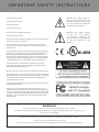
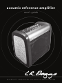
acoustic reference amplifier
user’s guide
R e l e n t l e s s
i n n o v a t i o n
i n
a c o u s t i c
a m p l i f i c a t i o n
C o n g rat u l ati o n s !
As an owner of this Acoustic Reference Amplifier, you now own a piece of audio history!
This is the first acoustic guitar amplifier to use a Flat-Panel Balanced Mode Radiator
speaker.
This single groundbreaking loudspeaker covers the entire audio spectrum for
breathtaking fidelity and outstanding clarity of the sound. Combined with the 140
degree wide dispersion of the speaker this amplifier will clearly reproduce the sound
of your guitar so that everyone hears the same clear, warm and delicious sound. It also
contains an all discrete professional studio quality preamp based on our award winning
Para DI to present the best quality signal possible to the speaker.
We trust that you are going to enjoy and come to understand the full capability of this
new amplifier as you play it. We have also included in this manual some tricks and tips
on how to get the most out of this amplification system.
T A B LE O F C ON T EN T S
Important Safety Instructions
Quick Start
About
Reference Amplifier
Balanced Mode Radiator (BMR) Loudspeaker
Industrial Design
Class-D Amplifier Module
All-Discrete Preamplifier
Spring Reverb
Positioning the Amplifier
The Cover
Front Panel Back Panel
Power Modules
Tricks, Tips and How-To’s
Setting the Gain
Getting the Most Out of Spring Reverb
Using the FX Loops
When, How and Why to Use Phantom Power
How to Use a Footswitch Daisy-Chaining Amplifiers (Linking More Than One Together)
D.I. Output Features
Speaker Limiter
Power Amplifier
Acoustic Guitar Feedback and Mic Feedback
Specifications
Block Diagram
Warranty
1
2
3
3
3
4
4
4
4
4
5-6
7-8
9
10
10
10
11
11
11
12
12
12
13
13
14
15
16
I M P O R TA N T S A F E T Y I NS T R U C T I ONS
• Read these instructions.
Wherever this symbol appears, it
alerts you to the presence of uninsulated dangerous voltage inside
the enclosure that may be sufficient
to constitute a risk of shock.
• Keep these instructions.
• Heed all warnings.
• Follow all instructions.
• Do not use this apparatus near water.
Whenever this symbol appears,
it alerts you to the presence
of
important
operating
and
maintenance (servicing) instructions
on the user’s manual for the
amplifier.
• Clean only with dry cloth.
• Do not block any ventilation openings. Install in accordance with
the manufacturer’s instructions.
• Do not install near any heat sources such as radiators, heat
registers, stoves, or other apparatus (including amplifiers) that
produce heat.
• Do not defeat the safety purpose of the polarized or groundingtype plug. A polarized plug has two blades with one wider than
the other. A grounding type plug has two blades and a third
grounding prong. The wide blade or the third prong is provided
for your safety. If the provided plug does not fit into your outlet,
consult an electrician for replacement of the obsolete outlet.
• Protect the power cord from being walked on or pinched
particularly at plugs, convenience receptacles, and the point
where they exit from the apparatus.
• Only use attachments/accessories specified by the manufacturer.
• Use only with the cart, stand, tripod, bracket, or table specified by
the manufacturer, or sold with the apparatus. When a cart is used,
use caution when moving the cart/apparatus combination to
avoid injury from tip-over.
• Unplug this apparatus during lightning storms or when unused
for long periods of time.
• Refer all servicing to qualified service personnel. Servicing is
required when the apparatus has been damaged in any way, such
as power-supply cord or plug is damaged, liquid has been spilled
or objects have fallen into the apparatus, the apparatus has been
exposed to rain or moisture, does not operate normally, or has
been dropped.
W A R NIN G
To reduce the risk of fire or electric shock, do not expose this apparatus to rain or moisture.
This apparatus shall not be exposed to dripping or splashing and no objects filled with liquids, such as beverages or vases,
shall be placed on the apparatus.
This device complies with part 15 of the FCC rules. Operation is subject to the following two conditions:
(1) This device may not cause harmful interference, and
(2) This device must accept any interference received, including interference that may cause undesired operations.
1
Q u ic k Start
Warning: Please read the Safety Instructions before using the amplifier.
1) MAKE SURE POWER SWITCH IS OFF - The “O” indicator on the switch is pushed in.
2) IF NEEDED, SELECT 230VAC SETTING - The amplifier is preset to the 115VAC setting (USA standard). If needed, select
the 230VAC (Europe) on the Voltage Selector using a coin or screwdriver.
3) PLUG IN THE AMPLIFIER - Plug the included power cable into the amplifier IEC Input Module first and then into the wall
outlet.
4) TURN MASTER VOLUME DOWN - Make sure the master vol is turned all the way counter-clockwise.
5) TURN THE AMPLIFIER ON - The “|” indicator is pushed in. As the power comes on the VU meter backlight should light
up. The amp may take a few seconds to come completely on.
6) PLUG IN THE GUITAR - Plug the cable into the guitar or instrument of choice and then into Ch1.
7) ADJUST THE GAIN - Strum the guitar to check level of the VU Meter as you turn the Gain control up clockwise (Optimally,
the VU meter is set correctly when the needle peaks around 0dB).
8) UN-MUTE CH1 (or Ch2 if you chose that channel) - Check the mute light. If it is lighted, then un-mute the channel by
pushing the mute button. The light should now be off.
9) ADJUST THE MASTER VOLUME - Turn the master volume knob clockwise to desired volume level.
10) ENJOY! - (repeat as necessary)
2
About
This section contains information about the design and construction of your Acoustic Reference Amplifier.
Reference Amplifier
When designing this product, we felt that the name “Guitar Amp” did not fully capture the capabilities of this product. In fact, we found
that we enjoyed listening to all kinds of live and recorded music through it. To us, it felt much more like a reference monitor than a guitar
amp. We began to test the quality by comparing it to audiophile speakers that are used in recording studios. Each time, the sound of this
product really grabbed us as having a quality much like a very good reference system. So, we decided we should call it what it really is
- an Acoustic Reference Amplifier.
Balanced Mode Radiator (BMR) Loudspeaker
At the heart of the amplifier is a patented Balanced Mode Radiator. The BMR is a new type of loudspeaker that
has its world debut in the Acoustic Reference Amplifier. It creates and radiates sound in a fundamentally
different and better way. This groundbreaking innovation is the brainchild of the eminent speaker
designer Dr. Graham Bank and was specifically adapted for acoustic guitar in collaboration with our
engineers. Exclusive to LR Baggs, this fully custom flat 8” honeycomb-diaphragm speaker employs
a single 2” voice coil to generate a 140-degree wide full range conical sound field with a clean SPL
of 108 dB. As all frequencies are generated by the one flat diaphragm, there are no crossovers or
time distortions to smear and muddy the sound. Harmonics align naturally with fundamentals, so
clarity and detail are breathtaking but without the normal harshness or annoying directionality
of a multi-driver system.
Unlike conventional multi-driver loudspeakers, the new BMR design combines the best features of
pistonic behavior, for low frequency control, with the best features of bending wave sound creation
for wide high frequency dispersion. This behavior closely mimics the way a guitar top generates
sound. This organic connection between the guitar and the BMR speaker makes it ideal for bringing the
voice of the acoustic guitar to life.
Industrial Design
An important factor in the Acoustic Reference Amplifier is the visual design. We spent countless
hours talking about how to design a product to fit alongside your coffee table as well as being a
high profile and durable stage feature. We wanted to have the feel of new, cutting edge design and
combine it with the feel of acoustic instruments.
Conventional Loudspeaker Dispersion
This led us to the rugged “Structural Foam” casing that is made out of the same material that flight
cases are made with. The wood panels are designed with a slight “retro” look but with a touch of
modern flair. The aluminum handle was designed to get rid of the old rubber-strap amp handle and
have the handle integrated into the overall design. The other metal portions such as the steel grill
and the aluminum back panel are durable features to protect the components inside.
BMR Wide Dispersion
3
Class-D Power Amplifier
Although digital amplifiers are not new, they have developed by leaps and bounds over the last couple of years. One of the major benefits
of digital amps is that they are very efficient. Due to this, they do not need large power supply components that make amplifiers very
heavy (think of an original Fender Twin). This is one of the ways that we have kept the weight of the Acoustic Reference Amplifier to a
mere 28 lbs. But weight isn’t everything. We also tested this digital amplifier against some of the top audiophile amplifiers available such
as VTL (Vacuum Tube Logic), Counterpoint, Meyer PA systems and other standard references. In blind AB testing our digital amplifier was
equal or superior to every reference.
All-Discrete Preamp
When electronics used to be built with vacuum tubes, there were very few parts in the signal path to “muddy” the sound. As transistors
were invented, much of electronics changed as now you could do many things that were not possible with bulky glass tubes. Since then
new devices called operational amplifiers (op amps) were invented to make certain tasks even easier and more efficient. However, making
things easier sometimes causes you to sacrifice some of the benefits of the older way.
Our engineering practice is to blend the best of the old with the best of the new. That is what we have done with this amp. We use digital
circuitry where it can be most effective - the efficiency of a Class D power amp. We use op-amps for what they do best - control circuits.
And we use discrete transistor stages for what they can do - clean and light audio controls with lots of features that don’t sacrifice the
tone (op amps in the signal path are the audio equivalent of microwave food). Where op-amps tend to add cloudiness and noise, we have
kept our preamp’s signal path 100% discrete so that the sound you get out is the sound you put in, or better.
Spring Reverb
During the design of this project, we were originally testing digital effects and planned on having them available on this amplifier. The
more we listened to the digital effects that were available on the market, the less satisfied we became with their quality. So we had the
idea of trying to make an analog spring reverb sound good for acoustic guitar. We eventually came up with a modification to the triedand–true Accutronics reverb that allowed us to have a reverb we felt proud of. So, we decided to opt for one great reverb effect with the
option of effects loops rather than a few “okay” sounds that would eventually become obsolete. We hope you enjoy this reverb as much
as we do.
Positioning the Amplifier
An acoustic guitar amplifier can be affected sonically by its location in the room. With other amps, it is usually necessary to place the
amplifier on a chair or lean it back to hear it while playing due to the very narrow dispersion pattern of traditional tweeters. However, with
the 140 degree wide dispersion pattern of the Acoustic Reference Amplifier, it will not be necessary to do so.
We have designed the amplifier to be used on the floor. Your best results will be with the amplifier on the ground and somewhat centered
in the room.
The Cover
As a further protection for your amplifier, we have designed and included a sturdy nylon cover. The cover is fitted with an elastic band to
make sure that it remains on the amplifier during transportation. There is a hard plastic sheet sewn into the top to protect the controls.
As well, there is a closeable pocket along the back to keep any extra cables, picks, strings or whatever else you need to keep in it.
4
F r o n t Pa n e l
1
2
3
4
5
6
7
8
9
10
11
12
13
1) Phantom Power and indicator LED
IMPORTANT NOTE: You should always have the channel muted, the gain turned down or the master volume
down when activating or deactivating the phantom power button.
14
This control supplies both +48V phantom power on the XLR input and +9V “pull-up” power on the 1/4” input. Use
the 48V on the XLR for microphones requiring phantom power such as a condenser mic. The 48V will also power
an LR Baggs Para Acoustic D.I. if you would like to use one. The 9V power on the 1/4” is for products that require
a “pull-up” supply such as an electret microphone capsule or the LR Baggs Buffer Jack and is supplied through a
15k ohm resistance.
The indicator LED lights to show that phantom power is “ON.” It is generally good practice to keep Phantom Power off when it is not in
use. The button is recessed to ensure that the power does not become accidentally activated. You may use a guitar pick, pen, or long
fingernail to press in the pushbutton switch.
2) Guitar and Microphone Input (1/4” and XLR combo jack)
The 1/4” central input is an unbalanced (mono) all discrete input with a 10 megohm impedance. It can be used with passive piezo pickups,
passive magnetic pickups or any standard active system.
The external ring on the same jack will connect an XLR to an all-discrete ultra-quiet balanced microphone preamp. The XLR input is
balanced (mono) like any common microphone input and has an input impedance of 6.8K ohms on each leg of the balanced line. This
input will work with almost any microphone, D.I. system or XLR connection.
3) Gain
The gain control is a very important feature on this amplifier. It combines the gain and individual channel level of both the XLR and the
1/4” input onto one control. The appropriate way to set this control is to increase the gain until the needle on the VU Meter begins to
peak around “0dB” at your loudest playing level. For more detailed information, read the “Setting the Gain with the VU Meters” section of
the TRICKS, TIPS AND HOW TO’S section.
4) VU Meter
The VU Meter gives you a useful visual tool to appropriately set the right amount of signal that will be running into the amplifier. The
signal should be clean well into the red and even just to the “needle-stop” point. However, the best headroom and signal-to-noise will be
found when the needle peaks just at “0dB” when playing at your loudest.
5) Mute and indicator LED
Each channel has a mute button that is much like a channel mute on a mixing desk. When the button is in, the signal will be muted. When
the button is out, the signal will not be muted. When muted, the LED above the mute button will light.
Because it is a channel mute, this function will not mute the speaker, only the incoming signal on each of Ch1 or Ch2. The aux input will
NOT be muted using the mute functions so that you may play background music. As well, the tuner output and the VU meters will not be
muted by the mute function.
This mute function may also be controlled by the “footswitch” option on the back of the amplifier. When a footswitch (not supplied) is
used to mute the signal, then both channels will mute at the same time. The pushbuttons on the amplifier will then be disabled from
un-muting the signal. If the channels are muted using the pushbutton mute on the amp then you cannot use the footswitch to bring the
signal out of mute. Mute on the pushbutton or on the footswitch will always dominate any attempt to unmute.
5
6) Notch
This amplifier incorporates the Garrett Null anti-feedback notch filter found on many of our preamps. Sonically it is virtually invisible
and it can be used to sweep the primary feedback range of the guitar (60Hz - 320Hz) to cut out a frequency that is causing feedback
or ringing. This control can also be disabled and taken out of the signal path by turning the knob all the way to the counterclockwise
position. You will feel a click as the filter is switched out.
To appropriately set the notch, turn up the guitar until it starts to feed back slightly and then turn the control from counterclockwise to
the clockwise position slowly. As the notch hits the trouble frequency, the feedback will stop.
7) Phase (Invert)
Press this button to invert the polarity of the signal. When the button is out, the speaker will be in phase with the input signal. The phase
relationship that is most important is the movement of the guitar top in relation to the movement of the speaker in the amplifier. A phase
relationship changes approximately every 4 feet that you move relative to the speaker so you must set this control according to where
you will be standing as you play. A correct phase relationship will sound best and be least likely to feed back. We recommend trying both
phases each time you set up as it will often change at each venue you play.
8) Bass
The bass control is a 12dB boost/cut centered at a frequency of 100Hz. For help with setting the EQ see “Helpful EQ Settings” in the TIPS,
TRICKS AND HOW TO’S section.
9) Low Mid Level and Frequency
The low mid control has two adjustable concentric knobs. The top knob controls the 12dB boost/cut. The bottom knob selects the
frequency at which you boost or cut. You can sweep from 200Hz (full counterclockwise) to 1kHz (full clockwise). The most common uses
of this control will be to dampen some of the low midrange frequencies on a muddy-sounding guitar or to boost a little of the lower
midrange frequencies on a thin-sounding guitar. For help with setting the eq see “Helpful EQ Settings” in the TIPS, TRICKS AND HOW TO’S
section.
10) High Mid Level and Frequency
The high mid control has two concentric adjustable knobs similar to the low mid control. The top knob controls the 12dB boost/cut. The
bottom knob selects the frequency at which you boost or cut. You can sweep from 1kHz (full counter clockwise) to 5kHz (full clockwise).
The most common uses of this control will be to cut some midrange frequencies on “nasal” sounding guitars or to boost frequencies up
in the 5k range to bring “zing” back to lifeless strings. For help with setting the eq see “Helpful EQ Settings” in the TIPS, TRICKS AND HOW
TO’S section.
11) Treble
The treble control is a 12dB boost/cut centered at a frequency of 10kHz. For help with setting the eq see “ Helpful EQ settings” in the TIPS,
TRICKS AND HOW TO’S section.
12) Reverb
This knob sets the level of the onboard Spring Reverb effect (has no impact on the fx loops). The control will not allow for 100% wetness
but does allow enough reverb to be “too much”. For more details regarding this feature please read the “Spring Reverb” notes in the
ABOUT section above and the “How to Get the Most Out of the Spring Reverb” instructions in the TIPS, TRICKS AND HOW TO’S section.
13) Master Vol and Clip LED
The master volume, located in the upper right of the control panel, will be used to set the level of the sound coming out of the speaker.
The main output also has a limiter on it (see “Speaker Limiter” in the TIPS, TRICKS, AND HOW TO’S section). The clip LED will light as the
limiter begins to engage. There should not be much of a sonic change caused by the limiter. It simply limits the volume to keep from
overheating the speaker driver.
As well, the master vol is also used to control the headphone volume when you have headphones plugged into the Headphone output
(the speaker will be disabled at this time). The master vol can also be set up to control the level of an extension amplifier or powered
cabinet by way of the Line Out (see “Daisy-Chaining Amplifiers” in the TIPS, TRICKS AND HOW TO’S section).
14) Aux Vol and Clip LED
The aux volume control, located in the lower right of the control panel, will be used to set the level of the auxiliary input on the back of
the amplifier. This input is either 1/4” (TRS summed stereo) or RCA jacks (for an MP3 or CD Player). A clip light is also supplied to show the
maximum possible level. There is a lot of headroom on this particular input so you may put in a very large signal and never see the LED
light up. The control is located on the front of the amplifier for easy access.
6
B ac k P a n e l
1
2
3
4
5
6
7
8
9
10
11
12
13
14
1) D.I. Pre/Post Switch
This pushbutton switch allows you to add the eq and internal reverb to the D.I. output or to send a “dry” signal straight from the Channel
Input Stage. When playing live or recording in a venue where you have an audio engineer that will set a mix for you in the house, you
will usually want to send them a “dry” signal, with no eq or reverb and let them set the sound for the house P.A. System. This is the most
common way to D.I. your signal so we have made this the default “out” setting. When in a situation where you must have complete control
of your own sound in the P.A. System, you can push this button “in” to send the same signal you hear from the amplifier with the P.A.
System.
2) D.I. Out
The D.I. output is a balanced XLR male jack. This is a common way to connect directly into the microphone input on a mixing desk with
a standard microphone cable. The signal level will be at around a -10dB at a 300 ohms impedance level so you will have plenty of signal
strength to send down long cables.
3) D.I. Ground Lift
This pushbutton may help defeat ground loop buzz that may occur if the amplifier is run through the D.I. output to the mixing desk. A
ground loop is caused by multiple paths to the Mains Earth Ground by way of more than one piece of equipment. However, in many cases,
using a ground lift switch such as this is sufficient. Heed this warning:
WARNING: Never use a 3-Prong to 2-Prong adapter on the power plug nor break off or disconnect
the ground connection of a power plug in order to defeat a ground loop or for any other reason.
This is very dangerous and can lead to electric shock, injury or death.
4) Line Out
The 1/4” line output has two distinct uses. First you can use it as a standard, pre-master line level output that is an alternative to the XLR
D.I. out. The line out will always be post eq and post internal reverb. However, you can switch the line out to be post master vol as well.
The benefit of this is when linking to a separate powered monitor or amplifier, you can use one volume control to adjust the volume level
of both cabinets. This is often called “Daisy-Chaining” and is described in the “Daisy-Chaining Amplifiers” part of the TIPS, TRICKS AND
HOW TO’S section.
5) Line Out Pre/Post Switch
This pushbutton switches the line output from being pre master vol or post master vol. See “Line Out” directly above for a brief description
or “ Daisy-Chaining Amplifiers “ in the TIPS, TRICKS AND HOW TO’S section for more details.
NOTE: Be careful when switching from post master vol to pre master vol because the volume will come on fully.
6) Headphone Out
All discrete, left and right stereo headphone output for playing your guitar with the amplifier’s speaker shut off. When you plug into this
jack, the amplifier’s speaker is automatically muted.
7
7) Ch1 Send
The output for a series effects loop on channel 1. Connect an unbalanced 1/4” cable from this jack to the input of an effects pedal or rack
device. If only the send is connected, the signal is not interrupted so you could use this as an independent 1/4” output as well.
8) Ch1 Return
Connect the return from the output of an effects pedal or rack device to complete the effects “loop.” When you plug into the return, the
throughput of the amplifier is interrupted (thus a series effects loop) so that the entire signal runs through your effects device. You will
have to appropriately set the level and effects levels according to the controls on your external device.
9) Ch2 Send
The output for a series effects loop on channel 2. Connect an unbalanced 1/4” cable from this jack to the input of an effects pedal or rack
device. If only the send is connected, the signal is not interrupted so you could use this as an independent 1/4” output as well.
10) Ch2 Return
Connect the return from the output of an effects pedal or rack device to complete the effects “loop.” When you plug into the return, the
throughput of the amplifier is interrupted (thus a series effects loop) so that the entire signal runs through your effects device. You will
have to appropriately set the level and effects levels according to the controls on your external device.
11) Aux In 1/4” Stereo
This input is a summed-stereo input allowing you to plug in another signal to mix with the other two channels. This can be used for a
third instrument, a backing track or any other standard analog audio device. The gain level is not set for passive devices but is designed
for use with CD Players, iPods and other strong signal levels. You may need a separate preamp for quieter devices used with this input.
The aux channel is not muted by the front panel mute controls or by the footswitch mute so that you can play background music while
in between sets and have your instruments or microphones muted. However, there is a volume control for the aux channel located on the
front panel in the bottom right corner to adjust the aux input level.
12) Aux in RCA Parallel
This dual RCA input is joined with the 1/4” aux input so you will generally want to use one or the other (although you could mix more
than one signal into these inputs if you really wanted to). The RCA inputs are provided so that you can connect an MP3 player (such as
an iPod), CD player or some other device commonly used with RCA jacks. This can be used for backing tracks or for playing music in the
background between sets. The aux channel is not muted by the front panel mute controls or by the footswitch mute so that you can play
background music while in between sets and have your instruments or microphones muted. However, there is a volume control for the
aux channel located on the front panel in the bottom right corner to adjust the aux input level.
13) Tuner Out
A pre-mute output made up of the combined Ch1 and Ch2 signals so that you may mute the speaker to tune your instrument.
14) Footswitch
This connection can be used with a standard unbalanced 1/4” cable and a shorting footswitch (not provided). When the connection
between the Tip and the Sleeve (ground) of the cable is not connected (called “open”) then the signals are not muted. When the Tip is
shorted to the Sleeve, both Ch1 and Ch2 are muted.
When the footswitch is activated, the mute indicator LED’s will light up. Either the footswitch or the onboard mute pushbuttons will
always be most dominant when in the mute position. This means that if the channel is muted at the amp, the footswitch cannot bring
this channel out of mute nor will switching the pushbuttons at the amp cause the footswitch to come out of mute. You can still use the
pushbuttons on the amp to mute the signal when a footswitch is connected to the amplifier.
8
Power Modules
1) Voltage Selector Switch
You must correctly select the appropriate voltage for the location in which you will be using the
amplifier. The markings are for 115V 60Hz and 230V 50Hz because these are the most common.
However, the power supply is able to handle a wider range of power options shown in the
SPECIFICATIONS section towards the end of the User Manual.
2) Power Switch
The power switch will turn the unit on and off. For safety purposes, be sure to disconnect the power
cord when the amplifier will not be in use for long periods of time.
The “|” indicator at the top of the switch indicates that the switch is “on” when that side of the switch
is pushed in. The “O” indicator at the bottom of the switch indicates that the switch is “off” when that
bottom portion of the switch is pushed in. You should always have the switch in the “off” position
when plugging in and unplugging the power cord.
3) Power Input Module with Fuse Holder
The IEC input will accept any standard connection such as a computer power cable. For simplicity, the
fuse holder is built into this mains connection. The fuse type should be: slow blow, time-lag, 5mm x
20mm, 250V. See below for amperage rating.
To access the fuse drawer:
1. Make sure that the power plug is disconnected from the Power Input Module.
2. With a small screwdriver, coin or fingernail, pry the fuse drawer out by using the small tab at the
top of the fuse drawer, which is just above the symbol of the fuse on the drawer.
3. The drawer contains a slot for the working fuse (the back, exposed slot) and a space for an extra
fuse (the front enclosed space).
4. READ THE WARNING BELOW BEFORE CHANGING THE FUSE.
In most cases, the T2.5AH fuse will be sufficient for use in the 115V setting. However, under the most demanding circumstances such as
high ambient temperatures or long intense playing sessions (more than 2-3 hours of constant high level playing), the T3.15AH fuse might
be preferred. The power amplifier should perform just fine with the T2.5AH fuse. However, if you notice that you have blown a fuse that
was rated T2.5AH in the 115V setting only, you should try using a T3.15AH rated fuse. ONLY USE A 2.5AH FUSE IN THE 230V SETTING. DO
NOT USE A T3.15AH FUSE IN THE 230V SETTING.
NOTE: The amplifier is shipped with fuses that can be used for the 115V and the 230V setting.
For the 115V Setting use a T2.5AH (supplied) or a T3.15AH Fuse maximum.
For the 230V Setting use a T2.5AH Fuse only.
WARNING: THE FUSE SHOULD NEVER BE REPLACED BY ANYTHING OTHER THAN THE
APPROPRIATE FUSE. YOU SHOULD NEVER USE FOIL,
WIRE OR ANY OTHER CONDUCTIVE MATERIAL TO REPLACE THE FUSE.
9
T ric k s , T ip s a n d H o w T o ’ s
1) SETTING THE GAIN WITH THE VU METERS
The knob labeled as “gain” next to the amplifier inputs is a control that combines three different functions. This knob gives you control
over the input gain of the 1/4” input (guitar cable), the input gain of the XLR input (microphone cable) and also sets the volume level of
the signal throughout the amplifier prior to the Master Volume.
The best way to set the gain is to plug in the instrument or microphone that you will be using in that particular channel. Keep the channel
muted until you finalize the setting. Play or sing at the loudest level you will be playing (if you play quietly while setting the gain and then
play loud while you perform, you may encounter some clipping distortion). While you are playing loudly, turn the gain control in the clockwise direction until the needle on the VU meter is hitting its highest point
just about or slightly above the 0dB mark on the VU meter. The gain is set at the ideal level when the needle is just barely going past the
0dB line at the highest peaks. When done appropriately, using the VU meter is a very quick way to get the appropriate signal from each
of your instruments for optimum performance of the amplifier.
2) GETTING THE MOST OUT OF THE SPRING REVERB
The spring reverb on this amplifier should be very simple and easy to set and use at an optimal level. In most cases, it is as easy as it seems
it should be - just turn up the knob and you get reverb. In general, reverb is used as a slight effect on steel string guitars and more heavily
on nylon string guitars. You should set it to your own personal preference.
For optimal use and a deeper understanding of how the controls will work on this amplifier please read the following two notes:
*An important note regarding spring reverb and mechanical stimulus:
A difference between spring reverb and digital reverb is that spring reverb is a mechanical device that uses an actual suspended spring,
inside the amplifier, to mimic the reverberation inside of a room. When the reverb is turned on, the electrical signal from a guitar pickup
or microphone will cause the springs to vibrate, thus creating the reverb effect. However, because the reverb is created by vibration,
you can also induce this vibration by accident. If, while the reverb is on, you bang or kick the amplifier, you may hear a “clanging” sound
coming from the reverb springs. We recommend that you always turn the amplifier off when moving or repositioning it. It is also a good
idea to make sure that the amplifier is not in a location where it may fall over or be hit while it is on, especially if you are using the spring
reverb.
The Channel Mute function will not mute the reverb. Only the Reverb control will turn this down or off.
**An important note regarding the reverb controls:
On many amplifiers, there is only one reverb knob to turn the same amount of reverb up on every channel. For more control, there can
be individual reverb level controls with a master reverb level knob. We wanted avoid the clutter of having one more odd knob on the
amp but still give the same individual level reverb controls on each channel. In order to do this, we had to allow for a certain amount of
“interaction” between the reverb level on Ch1 and the reverb level on Ch2.
This will be most noticeable when you have a certain reverb level set on one channel and then you turn up the reverb on the second
channel. Then, the reverb on the first channel will get slightly wetter. In most cases, this effect will be minimal. We felt that the usability
of the controls and the ease of not having to worry about other knobs is an asset that far outweighs the amount of interaction. However,
please take note of this when fine-tuning the amount of reverb you would like on the two channels.
10
3) USING THE EFX LOOPS
The EFX Loops on the back of the amplifier are individual channel effects loops. These loops allow you to plug in external effects devices
such as rack effects units, footpedals, in-line tuners, etc. in line with each channel. A standard mono guitar or instrument cable should
be used to go from the “send” jack to the input of the external effects device. Then another standard guitar cable is to be used from the
output of the external effects device and back into the “return” jack for that same channel.
It is important to not overload the “return” input of the amplifier by turning up the output of the effects device too high. Many rack
devices and some pedals have input and output volume levels. You should try to balance the level so that the signal coming from the
effects device into the amplifier is about the same level as the signal coming from the amplifier into the effects device. You can do this by
unplugging the effects device and seeing if the volume is now much louder or quieter and then balancing accordingly.
The EFX Loops are put in series with the signal path of the channel strip inside the amplifier. The signal is not interrupted until a cable is
plugged into the “return” jack. So, if you need a line level output for the individual channel, you may take a channel line out from the send
of each effects loop without affecting the signal path of the amplifier (unless this is shorted to ground - then the signal will mute).
A third use of the effects loop would be to plug a low impedance, high output device directly into the signal path and bypass all of the
eq and input circuitry of the amplifier, if so desired. The signal from the input would be switched off and the signal would come directly
from the “return” jack. However, you could simply use the aux input for this kind of setup.
NOTE: See the BLOCK DIAGRAM section for a visual overview of the signal routing in the amplifier.
4) WHEN, HOW AND WHY TO USE PHANTOM POWER
Note: You should always have the channel muted, the gain turned down or the master volume off when activating or deactivating
the phantom power button.
The phantom power on this amplifier is a dual use control. It simultaneously turns on +48V power on the XLR input and +9V “pull-up”
power on the 1/4” input. Each channel has its own phantom power switch.
The +48V phantom power on the XLR input can be used to power a condenser microphone that requires external power. As well, it can
be used to power the LR Baggs Para Acoustic D.I. preamp if so desired. The +48V is effectively supplied through two 6.8K resistors which
is the industry standard for this kind of power. Phantom power will not harm most microphones that do not require it. Some unique
microphones may be damaged by phantom power so be sure to check the specification of your microphone before proceeding. We do
not warrant against damage to any device from the presence of Phantom Power.
The +9V “pull-up” power is a different type of phantom power than the +48V and is designed to be used with “pull-up” FET devices such
as microphone capsules, and preamps such as the LR Baggs Buffer Jack. It is supplied through a 15K resistance, which is very common
and used on all of our “pull-up” supplies on other LR Baggs preamps. The +9V is supplied on the tip of the 1/4” input. If you have any other
questions about wiring your particular device, you should check with the manufacturer’s data for that device.
WARNING: If you are plugging in an active onboard preamp, be very sure that the phantom power is off. +9V power can damage
some active preamps. LR Baggs does not warrant damage to any device from phantom power.
5) HOW TO USE A FOOTSWITCH
The footswitch output is designed to allow you to use a standard shorting footswitch to activate the mute functions on both channels..
This way you can mute the device with your foot while you tune your instrument. Muting using the footswitch will activate the mute
function on both channels. When the footswitch pedal is used to mute, the mute LED’s will come on indicating that both channels are
muted. If the function is already activated at the amplifier, then the footswitch cannot bring them out of mute and vice versa.
11
The footswitch requires the use of a standard mono/instrument cable and a pedal designed to short the tip to the sleeve or the ring of the
cable (both will be grounded with a mono cable). When the tip is shorted to ground the signal will be muted. The signal is not actually run
down to the footswitch and back - it is a remote control. Therefore, the quality and length of the cable used is not important. Unshielded
cable such as speaker cable could even be used if necessary.
Do not try to put any signals into the footswitch jack. As well, do not connect the footswitch jack to the input of any device. Only use it
with a footswitch pedal.
6) DAISY-CHAINING AMPLIFIERS (LINKING MORE THAN ONE AMPLIFIER TOGETHER)
If you would like to, you may link more than one Acoustic Reference Amplifier together to allow for higher sound levels when performing
outside, in larger venues or for wider dispersion while playing in open areas such as patios. This will NOT put the amplifiers in stereo (see
note at bottom about stereo). The amplifiers will be connected in a mono chain with one acting as the main control. We have added a
feature on the amplifier to help you do this. The major benefit of running the amps in this “daisy-chain” mode is that you can do all of your
gain, eq, reverb, etc. on one of the amplifiers and control the output from the second amplifier directly from the first amp.
Here is how to set it up. You will need two Acoustic Reference Amplifiers - or one and a second powered monitor. Next to the line output
is a pushbutton labeled “pre/post master.” The standard setting is “pre master” in the out position so that you can take a line output
independent of the master volume. However, if you push it into the “in” position, you will be able to control the volume of the line out
directly with the volume of the speaker. Now run a standard 1/4” mono guitar/instrument cable from the line out and into the “aux in”
(preferred) or a channel input of the second powered amplifier. You will now just have to balance the output of the second amplifier using
the aux lev control and the master vol control. Once set, everything you do at the first amplifier will control the output of the second
amplifier. This includes muting, gain, reverb, eq, effects loops, etc.
STEREO: If you would like to run two amps in stereo, you will have to use an effects device that takes a mono input and creates a stereo
signal out of it. Or you can use a standard mixer. Run from “left” and “right” into either the inputs or “aux in” (preferred) and you have a
very good stereo PA. We have been very impressed with running these amplifiers in a stereo setup. Have fun!!
7) D.I. OUTPUT FEATURES
We have included two features on the D.I. output to make it more versatile for you:
First, on the right side of the D.I. output we have included a ground lift switch which may help remove a ground loop hum that could
occur if you have two powered devices connected together (such as connecting the D.I. output to a mixer). In our experience, a ground
lift switch works about half of the time. If you are having a terrible time with ground loops, you might want to look into some of the
many different types of filtering and ground lifting products on the market that claim to be able to defeat ground loops. Ground loops
are ultimately an issue with the wiring in the building and/or the setup of the PA and may be beyond the scope of this ground lift device.
When “lifted” the ground is connected through a 100nF capacitor and a 150-ohm resistor. Press the button in to lift the ground.
Second, on the left side of the D.I. output, we have included a pre/post switch that is designed to give you more control over what signal
you send from this output. The “pre” setting is with the pushbutton in the out position. In this position the signal is completely “dry.” It
comes directly after the input stage so that there is gain, but the eq, effects loops, reverb, notch, etc. will not affect the D.I. output signal. If
you depress the pushbutton switch, the D.I. output signal will come from after the eq, effects loops, reverb, notch, etc. The master volume
will never affect the D.I. output. Muting the input will cut that signal from the D.I. output in both pre and post modes.
8) SPEAKER LIMITER
The Acoustic Reference amplifier has a built-in limiter to protect the speaker. The limiter is completely transparent and will not be
noticeable during normal playing conditions. As you turn the volume up, you may notice that the volume simply stops increasing at
about 106dB. As the limiter engages the indicator LED next to the master vol control will begin to light up.
12
PLEASE NOTE: THE BMR LOUDSPEAKER IS NOT WARRANTIED AGAINST DAMAGE. EVEN THOUGH WE PROVIDE A LIMITER TO HELP PROTECT
THE SPEAKER, IT IS UP TO YOU TO NOT ABUSE THE LOUDSPEAKER. THIS DEVICE IS DESIGNED AS AN ACOUSTIC GUITAR AMPLIFIER AND IT
IS NOT RECOMMENDED TO PLAY ELECTRIC OR BASS GUITARS AT LOUD VOLUMES THROUGH THIS SPEAKER AS DAMAGE MAY OCCUR.
9) POWER AMPLIFIER
As with all power amplifiers, the ambient temperature may have an effect on the performance of the power amplifier in the Acoustic
Reference Amplifier. It is always best to have the amplifier sitting away from other heat sources and, in an outdoor venue, out of the direct
sun. The rear aluminum panel of the amplifier is designed to act like a heat sink and it may feel warm. This draws heat away from the
power amp. In most playing conditions, the ambient temperature will not be high enough to interfere with the power amplifier’s normal
operation.
10) ACOUSTIC GUITAR FEEDBACK
Feedback is caused by a particular resonance on a guitar being so strong that it is excited by the output from the speaker, which then
causes that frequency to be amplified louder by the pickup and thus exciting the guitar more. This is a loop that causes the volume to
increase at that frequency until it hits an equilibrium that is often very loud.
Our first tool in feedback prevention is the phase button (sometimes called “invert”). An acoustic guitar will usually feed back more often
in one phase versus the other phase at any given location. If you move around, the phase that causes feedback may switch because
moving about 3-6 feet towards or away from the speaker will cause the phase to flip in the primary feedback range for an acoustic guitar.
So, the first thing to do when fighting feedback is to try both phases by flipping the phase button on that channel in and out or simply
moving towards or away from the amp. The best phase is usually obvious unless you are positioned between the phase extremes.
Our second tool in fighting feedback is the notch filter. The frequencies that are most likely to feed back on an acoustic guitar are
determined by the size and the construction of the guitar. A larger bodied guitar will usually have a lower top resonance because of its
size and will usually feed back lower than smaller guitars that often have slightly higher-pitched fundamental resonance. The typical top
feedback frequency range is from 180 Hz–260 Hz.
The notch is designed to decrease the gain of the amplifier only at that specific frequency that is feeding back. This way, you can get more
volume without having that resonance feedback. The best way we have found to set a notch filter is to get the guitar to start feeding
back or “ringing” just slightly. It is never good to allow a prolonged or loud burst of feedback through a speaker as that can damage it.
However, just a light beginning of feedback for a short time is okay. Then, sweep the notch control from the counterclockwise position
slowly towards the clockwise position. As the very narrow notch passes the frequency that is feeding back, the notch will cause the
feedback to drop out. Now you can get more volume-before-feedback out of the amplifier. This specially designed Garrett Null notch that
we use on our products is almost transparent to the tone of the guitar (but of course improves it by getting rid of the feedback). The full
counterclockwise position will “click” to engage a hard-wire bypass to disable the notch.
If you are using these two controls and still need more volume before feedback then you can begin by reducing the low frequencies,
which will usually help reduce some of the feedback. However, this will also affect your tone. The key to fighting feedback is to remember
that you are trying to prevent feedback at lower levels but, as volume increases, you can always get to a situation where feedback can
occur. At high volumes, standing farther away from the amp can reduce the sound pressure level on the guitar top.
11) Microphone Feedback
The Phase and Notch controls are designed only for suppressing the primary feedback frequencies encountered in typical acoustic
guitars. They are not in any way intended to modify, suppress or eliminate feedback of a vocal microphone. Dealing with this sort of
microphone feedback is well understood in the craft and is beyond the scope of this manual. However the mic pre has substantial gain
so be very careful when using a vocal microphone.
13
Sp e cificati o n s
1/4” INPUT Input Impedance
Preamp Gain
Input Level
XLR INPUT
Input Impedance
Preamp Gain
Input Level
AUX INPUT
Input Impedance (1/4” mono)
Input Impedance (1/4” stereo)
Input Impedance RCA
Input Level EQ Notch
Bass
Lo Mid
Hi Mid
Treble
EFFECTS LOOPS
Send Level
Output Impedance
Return Level Input Impedance
D.I. OUT
Output level
Output impedance
LINE OUT
Output level
Output impedance
TUNER OUT
Output level
Output impedance
OUTPUT SPL MAX POWER AC Power Consumption
AC Current Draw
Voltage Range (115V Setting)
Voltage Range (230V Setting)
PHYSICAL CHARACTERISTICS
10 megohms
- ∞ to + 40dB
- 40dBv to +20dBv (.01Vrms to 3.53Vrms)
6.8K ohms (Each leg of balanced)
- ∞ to + 50dB
-50dBv to +12dBv (.003Vrms to 4.2Vrms)
6.6K ohms
20K ohms
20K ohms (each side)
-10dBv to +17dB (.3Vrms to 7Vrms)
- 21 dB, sweepable from 60Hz to 320Hz
(The notch is bypassed when clicked to the “off” position - full CCW)
+/- 12dB @ 100 Hz
+/- 12dB @ 500Hz, sweepable from 200Hz to 1kHz
+/- 12dB @ 2kHz, sweepable from 1kHz to 5kHz
+/- 12dB @ 10kHz
-5dBv (0.5Vrms)
600 ohms
+6dBv (2Vrms) Maximum before clipping
20K ohms
-8dBv (0.4Vrms) Balanced
600 ohms
-10dBv (0.3Vrms)
600 ohms
-10dBv (0.3Vrms)
600 ohms
108dB at 1 meter (full range)
220W Max
230V = 1A, 110V = 2A Max
90V - 130V, 50Hz - 65Hz
190V - 260V, 45Hz - 60Hz
28 lbs, 17.50” Width x 12.25” Depth x 18.0” Height
* These specifications may change without notice.
14
B LO C K D I A G R A M
15
1 - Y e ar Limit e d W arra n t y
LR Baggs Corporation warrants that the LR Baggs Acoustic Amplifier you have purchased shall be free from defects in parts and
workmanship if used under normal operating conditions for a period of one (1) year from the date of purchase, except the speaker
components which are warranted for a period of ninety (90) days from the date of purchase. This warranty shall apply only to the original
purchaser. Please retain your sales receipt, as it is your proof of purchase covering your limited warranty. This warranty is void
without such proof of purchase.
If the product fails to function properly due to defects in materials or workmanship during the applicable warranty period, LR Baggs
Corp., at its discretion, will repair or replace it with no charge for labor or materials. This warranty applies only if the product is sold and
delivered within the U.S. by an authorized LR Baggs Dealer. Any repair or service performed by a person or entity other than an LR Baggs
Dealer is not covered by this limited warranty. Transportation costs are not included in this warranty.
This limited warranty becomes void if the product has been damaged by alteration, misuse, accident, or neglect. The foregoing constitutes
the only warranty made by LR Baggs with respect to the product and is made expressly in lieu of all other warranties express or implied,
including, but not limited to, implied warranties of merchantability or fitness for a particular purpose. In no event shall LR Baggs be liable
for property damage or injury resulting from failure of this product nor any loss of income, satisfaction or damages arising from the loss
of use of same due to defects or availability of same during service.
To Obtain Warranty Service:
1) Contact the LR Baggs dealer where you purchased your amplifier to see if they are an authorized LR Baggs repair center. If you cannot
provide the original receipt, the authorized LR Baggs Service Center may charge you for repairs.
2) If the LR Baggs dealer cannot service the amplifier, contact LR Baggs directly and we can recommend a local service center or you can
send the amplifier directly back to our factory.
3) Receive Return Authorization number (RA#) from LR Baggs before sending amplifier to factory and place number on outside of box.
(NOTE: IF AMPLIFIER IS RETURNED WITHOUT A VALID RA# ON THE OUTSIDE OF THE BOX IT WILL BE REFUSED)
4) Ship the amplifier freight prepaid to the address below and include a copy of your sales receipt and a note explaining the problem
along with your shipping address and phone number.
5) Amplifiers repaired under warranty at the LR Baggs factory will be returned to the customer UPS Ground freight, prepaid by LR Baggs
to any location within the continental United States. (NOTE: A Product that is returned to LR Baggs which is not covered by the terms
of the warranty will be repaired if possible and returned C.O.D. with billing for labor, materials, return freight and insurance.)
LR Baggs Corporation
Attn: Support Department
483 N. Frontage Rd.
Nipomo, CA 93444
16
483 N. Frontage Rd., Nipomo, CA 93444 · p 805.929.3545 · f 805.929.2043 · www.lrbaggs.com