1
USER MANUAL
2
LIST OF CONTENTS
1. IMPORTANT REMARK
04
2. INTRODUCTION
05
3. INSTALLATION
05
4. QUICK START
08
5. OPERATION AND USAGE
10
6. DRIVERS INSTALLATION
12
7. EFFECTS PROCESSORS
13
8. MIDI CONTROLLERS
19
9. SETTINGS MENU
21
10. FURTHER CONSIDERATIONS
23
11. TECHNICAL CHARACTERISTICS
24
12. CONFIGURATION DIAGRAM
25
13. FUNCTION LIST
26
14. FUNCTION DIAGRAM
27
15. BLOCK DIAGRAM
28
All numbers subject to variation due to production tolerances. ECLER S.A. reserves the right to make changes or
improvements in manufacturing or design which may affect specifications.
3
1. IMPORTANT REMARK
Safety Instructions
In order to get the optimum operation and efficiency from your mixing unit, it is VERY IMPORTANT - before you
plug anything - to read this manual very carefully and take seriously into account all considerations specified within
it. We strongly recommend that its maintenance be carried out by our Authorised Technical Services.
This apparatus must be earthed through its mains cable.
Do not expose the unit to rain or water splashes, and do not place liquid containers or incandescent
objects like candles on top of the unit. Do not obstruct the ventilation shafts with any kind of material.
Any change in the configuration of the unit must be carried out by a qualified technician. Should any
connection / disconnection task be done, always disconnect the unit from the mains supply.
Warranty Descriptions
Your ECLER equipment has undergone exhaustive laboratory and quality control tests before leaving the factory.
Nevertheless, your may be in need of our Technical Service during the period covered by the Guarantee or
afterwards. In that case, carefully protect your equipment in its original packet and send it to our Technical Service
with the transport and insurance paid. Attach a photocopy of your Guarantee Certificate and a detailed description
of the defect you have observed.
ECLER S.A. guarantees the EVO4 mixer against material defects and manufacturing faults for the period of one
year, starting from the original purchase date.
ECLER, S.A., will repair the defective equipment within the aforementioned period, with no charge for parts and
labour.
To ensure the validity of the Guarantee, it is essential that the attached Guarantee, Registration Card is filled out
correctly and remitted to your ECLER distributor, within 10 DAYS after date of purchase.
The Guarantee is non-transferrable and protects the original buyer only.
The Guarantee does not cover:
Damages caused by mistreatment or negligent handling, lack of elementary precautions, disregard to the
instructions in the manual, faulty connection or accidents.
ECLER, S.A., will not be held responsible for any direct or indirect damage, loss or other damage originated by or
relating to the set.
* sets that have been manipulated, altered or repaired other than at the authorized Technical Service centers.
* the exterior fittings and electro-mechanical parts, nor their wear due to use.
* shipping and insurance expenses, nor for damages the set may incur during its transport.
This Guaranteed is valid only for repairs or services carried out at an authorized Technical Service Center.
A note regarding the LCD screens:
Our liquid crystal displays are manufactured with high-precision technology; however, different screens frequently
exhibit slight variances in the hue and brightness of their background lighting. This is not a malfunction.
4
Formázott
2. INTRODUCTION
Congratulations for acquiring a genuine, professional ECLER device! The EVO4 is the latest design from ECLER, a
legendary company from Barcelona with over 42 years of experience in designing and manufacturing professional
audio equipment.
With its top-of-the-line 96 kHz 24 bit digital audio, assignable MIDI controller, and two fully independent effects
processors, the EVO4 is the perfect tool for professional club DJs.
This genuine mixer uses the best available components and 24 bit 96kHz A/D and D/A converters in order to obtain
the best sound quality. Due to the over 40 years of experience in designing professional audio equipment, the
circuits are very efficient and the digital sound has the same warmness as any analogue device. All circuits are
manufactured and tested in our factory in Barcelona.
The EVO4 has two effect processors with 18 effects each in crystal clear 96 kHz 24 bit audio. These effect
modules, EFFECTS 1 and EFFECTS 2, are fully independent and can be assigned to the same or different
channels to chain up the effects. Both modules also include the innovative LOOP SAMPLER effect that makes it
easy for you to record and play back 1/8 to 8-beat loops in real time.
The EVO4 includes 29 MIDI controllers that can be assigned to the functions of your favourite software application.
For increased flexibility, the channels can be set to work independently as AUDIO controllers (PHONO, LINE or
MICRO) or as MIDI controllers. The top part of the mixer also has four encoder knobs/push buttons that work
exclusively as MIDI controllers.
The fact that the EVO4 lets you work with two separate effect boards and use MIDI to control your favourite
software application makes it the ideal mixer for today’s professional DJs.
3. INSTALLATION
The first thing to take into consideration when placing your EVO4 is your comfort and an easy access to all the
connections.
The EVO4 is basically conceived as a tabletop mixer and its usual placement
will be between two vinyls or CD players. The mixer has a 14.57’’ (37cm) depth
and 12.6’’ (32cm) width format.
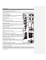
The optional metallic side profiles kit allows you to firmly fix your mixer to the
surface over which it is placed or over its own profiles (Fig.). These profiles
also allow to tilt the mixer's position for an easier operation. There is another
metal brackets option ('NUORAKI') that allows the mixer mounting in a
standard 19" rack.
Because of the high gain of the PHONO and MICROPHONE inputs, always try to place the mixer as far away as
possible from noise sources (dimmers, engines, etc.) and mains wires. For the very same reason, and under any
circumstance, you should never remove the unit's metallic cover.
The power consumption of the EVO4 is very low, so they do not need any cooling, but you should avoid extreme
temperatures and the atmosphere should be as dry and dust free as possible.
The EVO4 operates now with a new universal input power supply “Switching Power Supply” and can perfectly
works without any internal modification from 90V to 264V – 47 to 63Hz. Make sure that the mains-wire is far away
from the signal-cables in order to avoid any possible audio hum.
5
In order to protect the unit from an eventual electrical overload it carries a T 0.5 A fuse. Should it ever blow up,
unplug the unit from mains and replace it with an identical one. If the new fuse blows again contact immediately
with our authorized technical service.
ATTENTION: NEVER SHORT-CIRCUIT THE SECURITY PATH NOR USE A HIGHER VALUE FUSE.
CAUTION: Fuse substitutions have to be performed by a qualified technician.
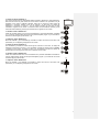
3.1. Audio input connections
PHONO 1
LINE 1
PHONO 2
LINE 2
PHONO 3
LINE 3
MICRO 4
LINE 4
Turntable
CD Deck
Turntable
CD Deck
Turntable
CD Deck
Microphone
CD Deck
Phono Inputs
Phono Turntables must be fitted with a magnetic cartridge with nominal output level between -60dBV and -20dBV
(1 to 100mV). The PHONO inputs (38) of the EVO4 have a high headroom (margin before saturation) and it can
handle higher output cartridges than what is usual. These inputs are supplied with a nominal input sensitivity of
-40dBV (10mV).
Line Inputs
The sensitivity of the inputs marked as LINE (39) is 0dBV (1V). You can connect sound sources such as CD, DAT
or MP3 players, as well as keyboards and other instruments.
Microphone Input
The MICRO input (40) are prepared for a nominal input level of -40dBV. The connector combine both, JACK and
XLR3, formats. With the TRIM controller it is possible to adjust the input sensitivity between -30 and -50dBV. These
microphone inputs are prepared for balanced signals, which have to be connected as follows:
Hot or direct signal
Cold or inverted signal
Ground
>
>
>
Pin 2
Pin 3
Pin 1
Tip
Ring
Sleeve
Microphones must have low impedance (200 to 600Ω) and must be mono. For unbalanced connections, it is
necessary to short-circuit pin 3 to ground or the central ring. The EVO4 equips an 18V phantom power supply for
condenser microphones. An internal soldering jumper allows enabling/disabling the phantom power. The EVO4’s
MICRO channel is delivered from factory with enabled phantom power. See configuration diagram.
6
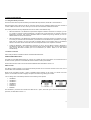
3.2. Audio outputs connections
OUT 1
OUT 2
REC
FX SEND/RETURN
REC posterior
Headphones
Main power amplifier
Booth/Room 2 power amplifier
Recording device
External effect device (Input and Output)
Recording device 2
Headphones
OUT 1
These stereo output connectors feeds to the PA system through balanced XLR3 or unbalanced RCA connectors.
The nominal output level for OUT 1 (45, 46, 47) comes standard at 0 dBV (1 V) but internal solder bridges may be
used to set it to +6 dBV. The output volume of OUT 1 can be regulated using the OUT 1 potentiometer (31).
The L+R switch (25) adds up the left and right signals from the OUT 1 and OUT 2 outputs. This function is
especially useful if there is a malfunction in one of the channels during a session (e.g. turntable needle does not
contact properly). When this switch is activated, the mixer sends the sum of L+R signals to both speakers, which
prevents most of the audience from noticing the malfunction.
OUT 1 and OUT 2 are equipped with a balance controller, BAL (26).
OUT 2
This output is usually used for independent output from the DJ booth. This stereo output, OUT 2 (48), is equipped
with unbalanced RCA connectors, and its nominal output level comes standard at 0 dBV (1 V), though internal
solder bridges may be used to set it to +6 dBV. The output level of OUT 2 can be regulated using the OUT 2
potentiometer (30).
Recording output
There is a REC output (44), which uses RCA connectors, on the back panel. The nominal output level for REC is
0 dBV (1 V).
FX Send/Return effects loop
The RCA connectors on the FX SEND output (42) and the FX RETURN input (43) allow creating a signal loop for
external effects processors, samplers or sequencers. The nominal level for the SEND output, as well as for the
RETURN input, is 0dBV (1V).
Headphones
In order to obtain an optimal performance during their operation, the headphones should have high impedance
(200-600Ω). Headphones are connected to the headphones output (36) located on the controllers plate. A
normalized ¼’’ stereo jack or 3,5mm mini-jack is provided for this connection. The sleeve is ground, the ring is the
right channel and the tip the left channel.
3.3. Digital connections
MIDI OUT
MIDI (Musical Instruments Digital Interface) is a standard communications protocol used for electronic musical
instrument-to-computer connections. MIDI devices may act as a master (controller) or slave (controlled) devices.
The EVO4 works as a master unit, meaning that it can control other electronic musical instruments (synthesizers,
sequencers, rhythm boxes, software and even light controllers). With the EVO4, MIDI CLOCK signals may also be
sent if this option has been enabled. A standard DIN 5 (180º) connector pin is used to establish a MIDI OUT
connection.
USB port
The EVO4 includes a USB-MIDI interface that allows you to send MIDI signals from the mixer to a computer via
USB.
You can also use the USB port to update the equipment’s firmware.
7
4. QUICK START
For the following procedure you will need a CD player and headphones.
1. Set the controllers to their initial position
Set the rotary controllers GAIN, HI, MID and LOW from channel 1 (17, 18, 19, 20) to the central snap-in position.
Put the channel fader (23) down and move the A/OFF/B switch (22) to position A (this channel is now assigned to
the crossfaders' A side).
2. Connect the headphones
Connect your headphones to one of the outputs on the mixer's front
panel (36). Set the MONITOR LEVEL (35) to minimum and move the
MONITOR SELECT control (34) to the PFL position.
3. Connect a CD player
Connect a CD player to LINE input on channel 1 (39), insert a CD and
play the CD.
4. Connect the mixer's power cable
Connect the power cable to power source input (54) on the mixer's back
side and turn the mixer on by pressing the MAINS INPUT switch (52).
5. Select the input source
Make sure that the input source selector on channel 1 (13) is in LINE
position and that the channel's VU-meter (16) lightens up. If this does
not happen make sure that CD player is correctly connected and that
there is an audio track being played back.
6. Adjust the input level
Turn the GAIN control (17) until the VU-meter shows 0dB. Each
channel's red overload LED OVL (14), lightens up if the input level for
this channel is to high and has to be diminished with the channel's GAIN
controller.
7. Send the signal to the main output
Set the fader on channel 1 (23) to maximum and place the crossfader
(24) on side A.
8. Listen to the signal with your headphones
Press the PFL button (21) on channel 1. Adjust the MONITOR LEVEL
controller (35) to obtain a comfortable monitoring volume. Now you
should hear music with your headphones. Turn the MONITOR SELECT
controller (34) to the right to crossfade the PFL signal and the MIX
signal. When this controller is completely turned to the right, only the
MIX signal will be monitored.
9. Try the operation of the tone controllers
Experiment with this powerful 3-way stereo equaliser (18, 19, 20). This
tone control has been designed for a creative sound edition: each way
can be individually isolated using the big and ergonomic rotary
controllers.
10. Check the adjustment of the crossfader
Each channel can be assigned to the crossfader using the A/OFF/B selector switch. The crossfader allows you to
melt the signals that are assigned to both of its sides. With this selector in position A or B, you assign the channel
to one of both sides of the crossfader. The OFF position disables the crossfader's function on this channel.
11. Adjust the crossfader curve
The XFADER SHAPE controller (33) allows a fine adjustment of the crossfader curve's slope. Setting this controller
all left, the signal is diminished when the crossfader reaches the central position, which allows mixing two songs
with a soft melting. The crossfader curve's slope increases if the controller is turned to the right. When is gets
completely turned to the right, the signal enters very fast with hardly a movement of the crossfader. This is very
useful for scratching.
8
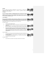
12. Select an effect "EFFECTS 1"
The EVO4 includes two fully independent effect processors, EFFECTS 1 and EFFECTS 2.
Both work the same way and contain the same number of effects. The processors may be
assigned to the same or different channels. Start out by playing an effect using the
EFFECTS 1 processor, located to the left of channel 1 on the mixer. To assign the
EFFECTS 1 processor to channel 1, turn the INPUT encoder (6) and press it when
CHANNEL 1 appears on the screen. To select an effect, turn the EFFECT encoder (7) and
select the desired effect by pressing the encoder when it appears on the screen.
13. Enable an effect "EFFECTS 1"
Press the LAUNCH button (12) and move the EFFECTS 1 processor DRY/WET crossfader
(11) to fuse the original (DRY) signal with the processed (WET) signal. If you would like to
monitor the effects signal, press FX PFL (10).
14. Adjust an effect "EFFECTS 1"
Move the PARAM 1 (8) and PARAM (9) controllers to adjust the sound of the effect. The
parameters you are adjusting will appear on the screen.
15. Select an effect "EFFECTS 2"
The EFFECTS 2 processor is located to the right of channel 4 on the mixer. To assign the
EFFECTS 2 processor to channel 1, turn the INPUT encoder and press it when CHANNEL
1 appears on the screen. To select an effect, turn the EFFECT encoder and select the
desired effect by pressing the encoder when it appears on the screen.
16. Enable an effect "EFFECTS 2"
Press the LAUNCH button and move the EFFECTS 2 processor DRY/WET crossfader to
fuse the original (DRY) signal with the processed (WET) signal. If you would like to monitor
the effects signal, press FX PFL.
17. Adjust an effect "EFFECTS 2"
Move the PARAM 1 and PARAM 2 controllers to adjust the sound of the effect. The
parameters you are adjusting will appear on the screen.
9
5. OPERATION AND USAGE
5.1. Start-up
To start up the mixer, press the switch (52) on the back panel. The two BPM LEDs will light up. “EVO4 ECLER” will
appear on the EFFECTS 2 screen and “LOADING” on the EFFECTS 1 screen.
All of the major output on the EVO4 are equipped with automatic mute circuits, which are activated whenever the
mixer is powered up or down.
Thanks to these circuits, the introduced noise due to turning the EVO4 on or off is the lowest possible. However it
is strongly recommended to turn on all the devices in the following order:
1. Sound sources.
2. Mixer, equalizers, active filters.
3. Finally, power amplifiers.
Powering off should be done by following the exact reverse sequence in order to avoid any possible damage to the
loudspeakers.
5.2. Control Description
5.2.1. Input selector
Channels 1-4 have a titling input source selector (13), allowing users to assign each channel to a turntable
(PHONO), a CD player or similar device (LINE) or a microphone (MICRO), respectively. This same selector can
also be used to put the channel in MIDI mode.
5.2.2. Channel GAIN
All the EVO4 input channels have an accessible input sensitivity GAIN control (17). The GAIN controls adjust the
input level of each channel in order to compensate the different sources connected to the mixer. The gain
adjustments have to be executed with extreme care using the VU-meters (16) and the OVL (14) as reference.
The standard reference level used to mix audio signals is 0dB. To obtain an optimal mix adjust the input level so
that the value shown on the VU-meter stays always close to 0dB and make sure you never reach the clipping level,
using the red LED’s from the VU-meter and the OVL indicator from each channel as reference.
5.2.3. Equalization
The rotary tone controls for each channels provide a +10/-30dB boost/cut at high (18) and low frequencies (20) and
+10/-25dB at the mid range (19). This great attenuation range is specially designed for creative live performance.
ATTENTION: Use equalization carefully, by boosting too much the low frequency range, you can induce an
excessive displacement of the speakers membrane.
10
5.2.4. Monitoring System
The EVO4 is equipped with an easy and flexible monitoring system that allows the artist to adjust with great
precision the effects and mix levels for each input channel using the VU-meters and headphones.
Each channel as well as the effect processing can be monitorized visually and pre-listened pressing the dedicated
PFL (21) and FX PFL (10) yellow led button. Each channel has a VU-meter that shows the PFL L+R signal level. A
main VU-meter with two columns L and R show the OUT 1, MIX or OUT 2 signal level, depending on the position of
the selector located just above the VU-meter (27).
For HEADPHONES monitoring, the SELECT PFL/MIX rotary potentiometer (34) allows you to blend a selected PFL
together and/or FX PFL with the main MIX Program. The LEVEL rotary potentiometer (35) controls the level of
headphones output.
5.2.5. Faders
The EVO4 equips ECLER's 60mm faders (23). These faders are very precise, their movement is very smooth and
they have a very fast cut.
The SHAPE FADER controller (32) adjusts the slope of the fader's curve, which allows you to distribute the signal
level over all the length of the fader. For example, you can select a linear curve (controller in central position), so
that the signal level is raised progressively and proportionally to the fader's position. Turning the controller
completely to the right, the signal enters at full level with hardly a movement of the crossfader. Turning the
controller completely to the left the signal enters at full level when the fader is about to reach the opposite side.
5.2.6. Crossfader
All of the channels can be assigned to the EVO4’s crossfader using the A/OFF/B switches, located on each of the
channels (22). Positions A and B assign the channel to one or other side of the crossfader, while the OFF position
disables the crossfader’s function on the respective channel.
The SHAPE XFADER (33) adjusts the slope of the crossfader's curve. The range of adjustable positions allows the
creation of a soft melting between two music tracks (controller set completely to the right side), as well as fast cuts
which are excellent for scratching techniques (controller set completely to the left side).
5.2.7. Internal effects controls
Please read chapter 7.
5.2.8. OUT 1 and OUT 2 output levels
The EVO4 equips two main output controllers OUT 1 (31) and OUT 2 (30). The OUT 1 (45, 46, 47) level can be
adjusted with the OUT 1 potentiometer while the OUT 2 controller adjusts the OUT 2 (48) level. Both can be
monitored with the main VU-meter using the OUT1/MIX/OUT2 switch (27) and can also be edited with the L+R
controller and the balance controller (BAL).
OUT 1 is equipped with a programmable limiter and is password protected (see section 9.2).
11
6. DRIVERS INSTALLATION
6.1. Drivers installation
The mixer comes with an installation CD and a USB cable. The drivers must be installed on your computer for you
to carry out firmware updates and to use MIDI to control any sort of DJ software.
The EVO4 is compatible with the Windows® XP SP2 and Macintosh® OSX v 10.X operating systems. Follow the
instructions below to install the drivers.
Windows® XP (home or professional)
1. Check that the EVO4 USB cable is disconnected and start your computer.
2. Run 'install.exe' program form the “Drivers” folder on the CD.
3. Install program will request the user to connect the EVO4 USB cable to the computer and to wait until the
operating system completes the drivers automatic default installation. Do not click 'Accept' until
Windows® XP tells you that the new device is ready to use (If you do it before, the installer tells you that he
can't complete installation and you have to restart the computer before retrying. Carefully follow all the
steps indicated in this manual). Caution: There may be a long pause while the operating system
detects the device until the end of the process.
4. Once Windows® XP tells you that the new device is ready to use, click 'Accept' to proceed with installation.
5. If XP Logo testing warning windows appears indicating that the driver you're going to install is not certified,
click 'Continue anyway' to proceed with installation.
6. Once the process completed, the EVO4 is identified as 'Ecler USB Midi' by the operating system and is
ready to use.
ATTENTION: If you connect the EVO4 to different USB ports on your computer, you'll have to repeat the
installation for each port and to restart your equipment each time.
We recommend visiting Ecler's web page (www.eclerdjdivision.com) in order to check if driver updates are
available.
EVO4 driver uninstall
In order to uninstall EVO4 drivers, disconnect first EVO4 USB cable from the computer. Run 'uninstall.exe' program
from the 'Drivers' folder on the CD.
1. Follow the wizard instructions.
2. Once the process completed, EVO4 USB-MIDI drivers are uninstalled from your operating system.
This utility uninstalls drivers for all ports on the same computer.
MAC OSX v 10.X
The software will automatically detect and install the necessary drivers. The mixer will appear as input/output
device in the "System settings" in the chapter "sound".
If you wish to use the mixer as default soundcard on your computer, open the "Audio and MIDI settings" and set the
necessary parameters.
12
7. EFFECTS PROCESSORS
7.1. Using the effects processors
The EVO4 comes with two powerful, BPM-synchronized effects processors, EFFECTS 1 and EFFECTS 2.
Both processors work at 96 kHz and 24 bit, and each comes with the 18 different effects, the same number of
controls, a BPM counter and an LCD, where you can see all of the information related to the effects.
The effects processors are fully independent and can be used in three different ways:
•
With the EFFECTS 1 and EFFECTS 2 processors assigned to different channels. For example, you can
run a Delay on channel 2 with the EFFECTS 1 processor and a High Pass Filter on channel 3 using the
EFFECTS 2 processor. This mode of operation allows for creative song mixing, because you can run
different effects on the two mix channels.
•
With the EFFECTS 1 and EFFECTS 2 processors assigned to the same channel. For example, you can
run a Delay on channel 2 with the EFFECTS 1 processor and use the EFFECTS 2 processor to run a High
Pass Filter on channel 2 as well. This mode of operation allows you be creative and run two different
effects on the same channel. Each effect can then be adjusted with its own respective controllers.
•
Linking the EFFECTS 1 and EFFECTS 2 processors. To do so, turn the INPUT encoder to EFFECTS 2
and select the LINK TO FX 1 option. This links the effects of both processors as in the prior example but
uses just one DRY-WET controller (the one for EFFECTS 2) to make it easier to run both effects
simultaneously.
7.2. Effects controllers
Each of the processors includes the effects controllers described below:
TIME UP/TIME DOWN buttons
The TIME UP and TIME DOWN buttons (4, 5) allow you to adjust the time in some effects. To increase the time of
an effect in beats, press UP. To decrease the time of an effect in beats, press DOWN.
These buttons are also used to control the LOOP SAMPLER effect described in section 7.3.
INPUT encoder
The INPUT encoder (6) allows you to assign the effects processor to one of the four channels on the mixer, one of
the two sides of the crossfader or the master.
When turning the INPUT encoder, a menu of available options appears on the screen. To choose one of the
options, turn the INPUT encoder to highlight the option and select it by pressing the encoder.
You can assign each of the effects processors to the following seven options:
•
•
•
•
•
•
•
CHANNEL 1
CHANNEL 2
CHANNEL 3
CHANNEL 4
XFADER A
XFADER B
MASTER
The EFFECTS 2 processor also includes the LINK TO FX 1 option, which also you to link it to the EFFECTS 1
processor, as described in section 7.1.
13
EFFECT encoder
The EFFECT encoder (7) allows you to select an effect from the processor. When turning
the EFFECT encoder, a menu with the different effects available appears on the screen. To
choose one of the effects, turn the EFFECT encoder to highlight the option and select it by
pushing on the encoder. There are 18 effects available. These are described in section 7.3.
If not turned, the EFFECT encoder also carries out the START function. The START function synchronizes the
instant of the music with the beginning of the selection BPM pattern. The START function also sends the MIDI
START and MIDI STOP commands by default.
PARAM 1 encoder
The PARAM 1 encoder (8) controls the first of the selected effect’s parameters. The value of PARAM 1 can be
seen its respective processor screen.
Pressing this encoder starts the TAP function, which lets you enter a rhythm sequence to manually synchronize the
BPM counter. You must enter at least 3 beats to validate a rhythm sequence.
PARAM 2 potentiometer
The PARAM 2 potentiometer (9) controls the second of the selected effect’s parameters. The value of PARAM 2
can be seen its respective processor screen.
FX PFL button
The FX PFL button (10) allows you to monitor the signal from the effects processor. The FX PFL signal is affected
by the DRY/WET crossfader (11).
DRY/WET crossfader
The DRY/WET crossfader (11) allows you to fuse the processed (WET) signal with the original (DRY) input signal.
LAUNCH button
The LAUNCH button (12) sends the post-DRY/WET crossfader signal to the program’s main mix output (MIX).
If LAUNCH is disabled, the effects signal is not sent to the main output, and the selected channel is processed
pre-fader. This allows you to monitor the effect settings in the headphones without affecting the main mix.
As soon as you enable LAUNCH, the signal processed by the DRY/WET crossfader is sent to the main output. The
channel selected is now processed post-fader, meaning that the mix of effect will also depend on the channel’s
fader.
14
7.3. Effect descriptions
HIGH PASS FILTER
This is a high pass filter (HPF) that attenuates the parts of a signal that are lower in
frequency. PARAM 1 regulates the filter’s resonance (RESO), and PARAM 2 controls its
frequency (FREQ). This effect is static and does not use TIME controllers.
LOW PASS FILTER
This is a low pass filter (LPF) that attenuates the parts of a signal that are higher in
frequency. PARAM 1 regulates the filter’s resonance (RESO), and PARAM 2 controls its
frequency (FREQ). This effect is static and does not use TIME controllers.
BAND PASS FILTER
This is a band pass filter (BPF) that passes signal frequencies in a certain range and
attenuates the rest. PARAM 1 regulates the filter’s resonance (RESO), and PARAM 2
controls its frequency (FREQ). This effect is static and does not use TIME controllers.
LFO HIGH PASS FILTER
This is a high pass filter (HPF) that introduces oscillating modulations to the beat, creating
a frequency sweep effect and attenuating the parts of the signal that are lower in frequency.
PARAM 1 regulates the filter’s resonance (RESO), and PARAM 2 controls its DEPTH. With
the TIME UP/DOWN buttons, you can adjust the oscillation cycle from 1:4 to 32:1.
LFO LOW PASS FILTER
This is a low pass filter (LPF) that introduces oscillating modulations to the beat, creating a
frequency sweep effect and attenuating the parts of the signal that are higher in frequency.
PARAM 1 regulates the filter’s resonance (RESO), and PARAM 2 controls its DEPTH. With
the TIME UP/DOWN buttons, you can adjust the oscillation cycle from 1:4 to 32:1.
LFO BAND PASS FILTER
This is a band pass filter (BPF) that introduces oscillating modulations to the beat, creating
a frequency sweep effect and passing only signal frequencies in a certain range, while
attenuating the rest. PARAM 1 regulates the filter’s resonance (RESO), and PARAM 2
controls its DEPTH. With the TIME UP/DOWN buttons, you can adjust the oscillation cycle
from 1:4 to 32:1.
SWEEP
This is a high pass + low pass filter effect that simulates VCF-style analogue filters.
PARAM 1 regulates the filter’s resonance (RESO), and PARAM 2 controls its frequency
(FREQ).
This effect is static and does not use TIME controllers.
BIT CRUSHER
This is a distortion effect that reduces the sampling rate of the digital signal (bit crushing).
15
DELAY/ECHO
This is a sound effect that consists of the repetition and modulated delay of a sound signal.
Once the signal has been processed, it is mixed with the original, resulting in the classic
sound echo effect. PARAM 1 regulates the FILTER, which allows you to attenuate the high
or low-frequency ranges of the signal. PARAM 2 controls the FEEDBACK, i.e. the number
of times that the signal is repeated. With the TIME UP/DOWN buttons, you can adjust the
time of the delay from 1:8 to 4:1.
PING PONG DELAY
This effect is similar to one described above except that the right channel lags slightly
behind the left channel. PARAM 1 controls the STEREO, and PARAM 2 regulates the
FEEDBACK, i.e. the number of times that the signal is repeated. With the TIME UP/DOWN
buttons, you can adjust the time of the delay from 1:8 to 4:1.
PHASER
This is a sound effect that consists of an all-pass filter, varying over time, that works by
modulating sections of signal that are out of phase with each other and then re-mixing the
processed signal with the original signal. These frequencies are modulated with a low
frequency oscillator (LFO) controlled by the music’s BPM rhythm to create a frequency
sweep Phaser sound. PARAM 1 regulates the FEEDBACK, and PARAM 2 controls the
DEPTH. With the TIME UP/DOWN buttons, you can adjust the oscillation cycle from 1:1 to
32:1.
FLANGER
This is a delay modulated by a low sine frequency oscillator (LFO) that is controlled by the
music’s BPM rhythm. This produces a highly dynamic swirling sound effect. PARAM 1
regulates the FEEDBACK, and PARAM 2 controls the DEPTH. With the TIME UP/DOWN
buttons, you can adjust the oscillation cycle from 1:1 to 32:1.
PITCH
This effect allows you to displace the pitch of an input signal without altering its duration. It
is usually used to change the key of the sound. PARAM 1 controls the PITCH by ±12 tones
in 100 steps.
TRANS
This is a volume transformation effect similar to the manipulation of a time-synchronized
fader.
PARAM 1 regulates the VOLUME, and PARAM 2 controls the DEPTH. With the TIME
UP/DOWN buttons, you can adjust the oscillation cycle from 1:4 to 32:1.
PAN
This is a panning effect, i.e. time-synchronized balance oscillation between the L and R
channels.
PARAM 1 regulates the PAN, and PARAM 2 controls the DEPTH. With the TIME
UP/DOWN buttons, you can adjust the oscillation cycle from 1:4 to 32:1.
16
REVERB
This is an effect that imitates the deterioration of sound waves in a space due to
reverberations against walls, ceilings, objects, etc. PARAM 1 regulates the TIME, and
PARAM 2 controls the DAMPING.
VOCODER
This is an effect that modulates a CARRIER signal using the signal from the channel
assigned to the effects channel. Using the UP/DOWN buttons, you can select the channels
going into the mixer as the carrier or the NOISE or SQR signals generated in the effects
module. You can use PARAM 1 to adjust the DECAY. When SQR is the carrier signal, you
can use PARAM 2 to adjust the PITCH.
LOOP SAMPLER
This is a phrase recorder/player. When this effect is enabled, you can use the TIME
UP/DOWN buttons to record, play or delete sound samples. Each effects processor has its
own sound bank; that is to say, there are a total of two sound banks, one in each processor.
The sound samples are stored in the memory of the EVO4 and remain there even if you
change effects; however, they are deleted when you turn off the mixer.
To record a sample:
1.
2.
3.
4.
Select the LOOP SAMPLER effect.
Use the INPUT encoder to select the input signal you would like to record the
sample from.
Make sure that there is no previously recorded sound sample (the LCD screen
should say EMPTY). If there is already a sample recorded, you must first delete
it.
Press the record button (●). Auto-record begins when the record button is first
pressed and finishes 8 beats later. If you hold down the record button, the
sample will be recorded manually. When the record button his held down, an
orange-coloured LED will glow, and the word REC will appear on the screen.
When you are finished recording, the button will turn green and the LCD screen
will say READY.
To play a sample:
1.
2.
Press the play button (►). The button will flash green, and the LCD screen will
say PLAY. The sample’s playback speed will be adjusted to the BPM of the
signal automatically.
To stop playback, press the pause button (). The button will remain green,
and the LCD screen will say READY.
To delete a sample:
1.
Press the ALT key and when it turns orange, hold it down as you press ●.
17
EXTERNAL FX
This is a loop that outputs a signal to external effects devices through the FX SEND and RETURN connectors on
the back panel of the mixer (42, 43). The EXTERNAL FX option can only be selected on one of the mixer’s banks.
The signal sent is pre-fader. DRY-WET control works the same as with internal effects.
7.4. BPM counters
Each of the effects processors, EFFECTS 1 and EFFECTS 2, includes a precise BPM counter that synchronizes
the effects in time with the music.
The BPM counters use the signal flowing into the effects module to base its calculations. Both are always active as
the default option, unless you activate the manual mode by pressing the TAP encoder 3 times. To return to AUTO
mode, hold down the TAP encoder for at least two seconds.
You may adjust the BPM detection margin in the SETTINGS menu (see section 9).
18
8. MIDI CONTROLLERS
8.1. Description
The EVO4 allows you to control external devices with the MIDI protocol. The functions of each MIDI controller are
set, and you must adapt your software or favourite external device to them.
MIDI (Musical Instruments Digital Interface) is a standard communications protocol used for electronic musical
instrument-to-computer connections. MIDI devices may act as a master (controller) or slave (controlled) devices.
The EVO4 works as a master unit to control other electronic musical instruments (synthesizers, sequencers,
rhythm boxes, software and even light controllers). The EVO4’s MIDI messages belong to the “Channel Messages”
and “System Messages” class. It is important for the devices that emit and receive these messages to use the
same channel, so that they can communicate with each other.
The MIDI OUT connector (49) sends all MIDI data generated by the EVO4 and is used to control devices with a
DIN5 connection. It also permits the transfer of the EVO4’s MIDI CLOCK signal, if this option has been enabled.
The mixer includes a USB-MIDI interface that allows you to send MIDI signals from the mixer to a computer via
USB.
8.2. MIDI controllers
The EVO4 includes 29 controllers that can send MIDI data:
•
•
•
•
•
16 potentiometers
4 buttons
4 dedicated encoder knobs/push-buttons
4 60 mm faders
1 45 mm crossfader
The controllers for channels 1, 2, 3 and 4 may operate independently as AUDIO controllers, if PHONO or LINE is
selected on the source selector, or as MIDI controllers, if MIDI is selected on the source selector. Each channel has
a blue LED (15) that lights up when it is operating in MIDI mode.
When a channel is operating in MIDI mode, the signal in its LINE input is sent to MIX. The VU and OVL work
normally, and the channel’s GAIN, PFL and FADER controllers double up their functions, sending MIDI data and
controlling the audio at the same time. As a result, you can adjust the input level (GAIN), listen to the signal in
advance (PFL) and adjust the level of output to MIX (FADER).
The EVO4’s crossfader always operates simultaneously in AUDIO and MIDI mode, regardless of the configuration
of the channels.
The top part of the mixer there is a MIDI CONTROL area with four encoder knobs/push-buttons. These encoders
always send MIDI data.
19
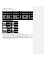
8.3. MIDI notes from the controllers
The EVO4’s MIDI controllers send the following notes:
CONTROL
Gain
EQ High
EQ Mid
EQ Low
On
Off
A
Sw XF Off
B
Fader
Xfader
PFL
Ch
01
01
01
01
01
01
01
01
CHANNEL 1
CC
Value
02
0-127
03
0-127
04
0-127
05
0-127
127
06
00
00
09
01
02
10
0-127
20
0-127
CONTROL
Clock wise
Encoder 1
Counter CW
Clock wise
Encoder 2
Counter CW
Clock wise
Encoder 3
Counter CW
Clock wise
Encoder 4
Counter CW
On
Encoder push 1
Off
On
Encoder push 2
Off
On
Encoder push 3
Off
On
Encoder push 4
Off
CHANNEL 2
CC
Value
02
0-127
03
0-127
04
0-127
05
0-127
127
02
06
00
00
02
09
01
02
02
10
0-127
Ch
02
02
02
02
CH
CC
00
59
00
60
00
61
00
62
00
55
00
56
00
57
00
58
CHANNEL 3
CC
Value
02
0-127
03
0-127
04
0-127
05
0-127
127
03
06
00
00
03
09
01
02
03
10
0-127
Ch
03
03
03
03
CHANNEL 4
CC
Value
02
0-127
03
0-127
04
0-127
05
0-127
127
04
06
00
00
04
09
01
02
04
10
0-127
Ch
04
04
04
04
VALUE
01-07
127-121
01-07
127-121
01-07
127-121
01-07
127-121
127
00
127
00
127
00
127
00
8.4. Assigning the functions of an external device to the MIDI controllers
Every device has its own MIDI configuration procedure. It is worth spending some time to gather in-depth
information about the MIDI control possibilities of your software/device and how to programme them.
It is very common for DJ software to include a “learner” mode. Select the function that you would like to control in
the DJ software, and when asked to do so by the device, move the controller on the mixer that you would like to
use to carry out this function. The DJ software will recognize the MIDI note sent by the mixer, and from then on,
you will be able to control that function remotely.
20
8.5. MIDI CLOCK
The EVO4 transmits a continuous synchronization code, known as MIDI CLOCK, which allows you to synchronize
one or more external MIDI devices. The MIDI CLOCK signal sent by the EVO4 is relative to the beats per minute
(BPM) calculated by the selected internal BPM processor (EFFECTS 1 or EFFECTS 2).
If you would like to synchronize external MIDI devices, remember that you must set these devices to slave mode
(external clock adjustment).
The MIDI CLOCK function may be chosen from the settings menu (see section 9). To choose this option, press and
hold the EFFECTS 2 INPUT encoder for two seconds. A menu will appear on the screen. Select MIDI CLOCK and
as CLOCK SOURCE, one of the following options:
•
•
•
OFF (no MIDI CLOCK signal sent)
FX1 (the EVO4 sends the MIDI CLOCK signal from the EFFECTS 1 BPM counter)
FX2 (the EVO4 sends the MIDI CLOCK signal from the EFFECTS 2 BPM counter)
Once you have selected the desired option, again press the EFFECTS 2 INPUT encoder and hold it for two
seconds.
When the EVO4 is transmitting the MIDI CLOCK signal, a symbol will appear in the LCD of the respective effects
processor.
When the mixer is set to send the MIDI CLOCK signal, the START button will generate the MIDI START and MIDI
STOP controllers, which indicate to the external device when it should began to detect the external clock signal
(which is required by some MIDI devices).
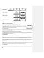
9. SETTINGS MENU
To access the settings menu, press the EFFECTS 2 INPUT encoder and hold it for two
seconds until the settings menu appears on the screen.
In the settings menu, you can program the following parameters:
INFO
LIMITER:
MIDI CLOCK
BPM RANGE: 60-120 BPM
70-140 BPM
80-160 BPM
90-180 BPM
100-200 BPM
110-220 BPM
21
FX PFL MODE
LCD1 CONTRAST
LCD2 CONTRAST
CHANGE PASSWORD
All settings will be maintained, even after the mixer has been switched off.
What to do if you forget a password
You can change the password with “CHANGE PASSWORD” function.
If you forget the password, press the EFFECTS 2 SELECT encoder on the INVALID
PASSWORD screen and hold it for three seconds. Contact ECLER with the code that
appears on the screen to receive the proper password.
9.1. Firmware Update
The EVO4 Firmware Upgrade application allows you to update the mixer’s firmware, so that you always have the
latest version of the software available.
Please visit our homepage to download the latest version of the software.
To update the firmware, connect the EVO4 to your computer with the USB cable. Then, run the update program
and follow the instructions on the screen.
9.2. Output limiter
To use this function, go to the settings menu.
When you select LIMITER, you will be asked for a password. The default password is ECLER. The settings menu
also includes an option to change it.
After you have entered the correct password, you may select a limit threshold of -10dB to +10dB or turn off the
output limiter (OFF).
9.3. MIDI clock
This option allows you to select the source of the MIDI CLOCK signal sent through the MIDI connector on the back
panel.
The options are OFF, EFFECTS 1 BPM counter (FX1) or EFFECTS 2 BPM counter (FX2).
9.4. BPM RANGE
With this option, you can select the automatic BPM (Beats Per Minute) calculation interval for both effect channels.
22
9.5 FX PFL MODE
You can select if the effects pre-listening will be affected by the DRY/WET control or not. If you select the PRE
DRY/WET option, the FX PFL signal will be the same that you would have when the DRY/WET control is in the
WET position.
23
10. FURTHER CONSIDERATIONS
10.1. Ground loops
Ensure at all times that no signal sources reaching the mixing desk and no devices connected to its output have
their earths interconnected; that is, earth should never reach them via two or more different paths, as this could
lead to humming which could even interfere with sound reproduction quality. In order to avoid earth loops, ensure
that the shielding of cables, if connected to the chassis, are never connected with each other.
10.2. Audio connections
As a general rule of thumb, make the signal connections as short as possible and use the best connectors and
cable available. Cables and connectors are frequently held cheap, forgetting that a bad connection can result in a
poor sound quality.
10.3. Cleaning
The front panel should not be cleaned with dissolvent or abrasive substances because silk-printing could be
damaged. To clean it, use a soft cloth slightly wet with water and neutral liquid soap; dry it with a clean cloth. Be
careful that water never gets into the unit through the holes of the front panel.
24
11. TECHNICAL CHARACTERISTICS
AD/DA 24 bits converter 96kHz
32/64bits DSP engine.
Frequency response -1dB (-3dB):
Line:10Hz – (47,5kHz)
Micro: 10Hz – (47,5kHz)
Phono: RIAA ± 0.5dB (20Hz – 20kHz)
Input sensitivity/Impedance:
Line: 0dBV/20kΩ
Phono:-40dBV/50kΩ
Micro: -50 to -30dBV / >1kΩ
Output level/Min. Load:
OUT1: 0dBV(+6 dBV hard configurable) / >600Ω
OUT2: 0dBV(+6 dBV hard configurable) / >600Ω
Output Limiter on OUT1: -10dBV to +10dBV compressor, password protected.
REC: 0dBV/10kΩ
Headphones: 0,2W/200Ω, 1%THD
Midi: USB / Din 5 180º
THD+N:
Line:<0,008%
Phono:<0,01%
Micro:<0,02%
Signal/N. Ratio:
Line:>97dB
Phono:>94dB
Micro:>92dB
CMRR: Micro:>70dB@1kHz
Shape: adjustable on Xfader & Faders
BPM: automatic from 60 to 220 bpm in 6 ranges, internal or MIDI clock reference.
Tones:
BASS -30/+10dB (200Hz)
MID -25/+10dB (200 & 6,5kHz)
TREBLE -30/+10dB (6,5kHz)
Built in squelch on unused channels.
Two independent loop sampler, 8+8 sec. max.
Phantom voltage: +17,5VDC/5mA max.
Input Gain: from -∞ to +10dB
Mains: 90-264VAC 47-63Hz
Power consumption: 31VA
Dimensions: 370x320x80mm
Weight: 5kg
* Specifications and appearance are subjected to change without notice. Since the software is
upgradeable, some values may differ from one version to another due to improvements.
25
12. CONFIGURATION DIAGRAM
26
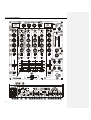
13. FUNCTION LIST
1. Display
2. BPM indicator LED, BPM
3. Control encoders, MIDI
4. Multifunction button
5. Multifunction button
6. Control encoder, INPUT
7. Control encoder, EFFECT
8. Control encoder, PARAM 1
9. Control encoder, PARAM 2
10. FX PFL monitoring switch, FX PFL
11. Effect mix crossfader, DRY-WET
12. Effect launch to PGM button, LAUNCH
13. Input selector
14. Overload indicator, OVL
15. MIDI mode indicator
16. LED VU Meter
17. Input sensitivity adjust, GAIN
18. Treble control, HI
19. Midrange control, MID
20. Bass control, LOW
21. Prefader listening control, PFL
22. Send to XF switch, A/OFF/B
23. Fader
24. Crossfader control, A-B
25. Left and Right signal sum, L+R
26. Balance control, BAL
27. VU-meter display switch, OUT1/MIX/OUT2
28. Overload indicator, OVL
29. LED VU Meter
30. Volume control, OUT 2
31. Volume control, OUT 1
32. Fader Shape adjustment, FADER SHAPE
33. Crossfader Shape adjuster, XFADER
34. PFL/MIX monitoring crossfade, SELECT
35. Headphones volume control, LEVEL
36. Stereo jack headphones
37. Ground pin, GND
38. Phono input, PHONO
39. Line input, LINE
40. Microphone XLR/JACK combo connector, MICRO
41. Micro input sensitivity adjustment, TRIM
42. External FX send output, FX SEND
43. External FX return input, FX RETURN
44. Recording output, REC
45. RCA output, OUT 1
46. Left channel balanced output, OUT 1 L
47. Right channel balanced output, OUT 1 R
48. RCA output, OUT 2
49. MIDI Output, MIDI OUT
50. USB port
51. Indicator LED for USB port, USB
52. Power switch
53. Fuse holder
54. Mains socket
27
14. FUNCTION DIAGRAM
28
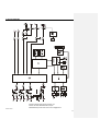
15. BLOCK DIAGRAM
ECLER Laboratorio de electro-acústica S.A.
Motors 166-168, 08038 Barcelona, Spain
INTERNET http://www.ecler.com e-mail: [email protected]
50.0159.01.00
29