1
31/01/96
SY546 User's Manual
Soft. Ver. 0.02 PRELIMINARY
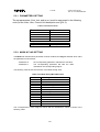
TABLE OF CONTENTS
TABLE OF CONTENTS .................................................................................................................................................1
1.
DESCRIPTION ..................................................................................................................................................3
2.
SPECIFICATIONS ............................................................................................................................................4
2.1.
2.2.
2.3.
2.4.
2.5.
2.6.
2.7.
PACKAGING......................................................................................................................................................................... 4
SYSTEM CRATE EXTERNAL COMPONENTS (SY546) .................................................................................................. 4
CRATE CONTROLLER EXTERNAL COMPONENTS (A547) .......................................................................................... 4
CRATE CONTROLLER INTERNAL COMPONENTS (A547) ........................................................................................... 5
ACTIVE DISTRIBUTOR EXTERNAL COMPONENTS (A548) ........................................................................................ 5
CHARACTERISTICS OF THE SIGNALS............................................................................................................................ 6
POWER REQUIREMENTS................................................................................................................................................... 6
3.
OPERATING MODES ......................................................................................................................................7
3.1.
INTRODUCTION .................................................................................................................................................................. 7
3.1.1.
3.1.2.
3.1.3.
CRATE CONTROLLER ............................................................................................................................................................................... 7
BOARDS CONTROL.................................................................................................................................................................................... 7
CONTROL AND MONITORING................................................................................................................................................................. 8
3.2.
POWER MODULES INSERTION ........................................................................................................................................ 8
3.2.1.
CHANNEL NUMBERING............................................................................................................................................................................ 8
3.3.
CHANNEL PARAMETERS .................................................................................................................................................. 8
3.3.1.
3.3.2.
3.3.3.
3.3.4.
3.3.5.
3.3.6.
3.3.7.
3.3.8.
3.3.9.
3.3.10.
3.3.11.
3.3.12.
3.3.13.
3.3.14.
3.3.15.
CHANNEL NUMBER (CH #) ...................................................................................................................................................................... 9
CHANNEL NAME........................................................................................................................................................................................ 9
VMAX HARDWARE ................................................................................................................................................................................... 9
VMAX SOFTWARE..................................................................................................................................................................................... 9
VSET PARAMETER .................................................................................................................................................................................... 9
ISET PARAMETER ...................................................................................................................................................................................... 9
RAMP-UP PARAMETER............................................................................................................................................................................. 9
RAMP-DOWN PARAMETER.................................................................................................................................................................... 10
VMON PARAMETER ................................................................................................................................................................................ 10
IMON PARAMETER.................................................................................................................................................................................. 10
TRIP PARAMETER.................................................................................................................................................................................... 10
POWER STATUS ....................................................................................................................................................................................... 11
CHANNEL STATUS .................................................................................................................................................................................. 11
PASSWORD PROTECTION STATUS ...................................................................................................................................................... 12
ON/OFF PROTECTION STATUS.............................................................................................................................................................. 12
3.4.
FRONT PANEL SIGNALS.................................................................................................................................................. 13
3.4.1.
3.4.2.
3.4.3.
RESET FUNCTION .................................................................................................................................................................................... 13
KILL (INPUT) ............................................................................................................................................................................................. 13
STATUS (OUTPUT) ................................................................................................................................................................................... 13
3.5.
3.6.
OUTPUT VOLTAGE CONTROL ....................................................................................................................................... 14
REMOTE CONTROL .......................................................................................................................................................... 15
3.6.1.
3.6.2.
RS232 PORT ............................................................................................................................................................................................... 15
H. S. CAENET OPERATION ..................................................................................................................................................................... 17
4.
TERMINAL OPERATION .............................................................................................................................18
4.1.
4.2.
MAIN MENU....................................................................................................................................................................... 20
DISPLAY/MODIFY CHANNELS OPTION ....................................................................................................................... 22
4.2.1.
4.2.2.
4.2.3.
4.2.4.
4.2.5.
EDIT PARAMETER SCREEN ................................................................................................................................................................... 29
CHANGE PARAMETER SCREEN............................................................................................................................................................ 31
ADD CHANNEL SCREEN......................................................................................................................................................................... 32
INSERT CHANNEL SCREEN ................................................................................................................................................................... 34
REPLACE CHANNEL SCREEN................................................................................................................................................................ 35
4.3.
4.4.
GROUP OPERATION OPTION.......................................................................................................................................... 36
PROTECTION OPTION ...................................................................................................................................................... 40
1
31/01/96
SY546 User's Manual
Soft. Ver. 0.02 PRELIMINARY
4.4.1.
4.4.2.
DISABLE PASSWORD AND KEYBOARD.............................................................................................................................................. 41
ENABLE PASSWORD ............................................................................................................................................................................... 42
4.5.
4.6.
4.7.
CONNECT A NEW CRATE OPTION ................................................................................................................................ 43
CRATE MAP OPTION ........................................................................................................................................................ 44
SELECT ALARM MODE OPTION .................................................................................................................................... 45
5.
H. S. CAENET OPERATION .........................................................................................................................46
5.1.
USING THE H. S. CAENET VME CONTROLLER ........................................................................................................... 46
5.1.1.
5.1.2.
5.1.3.
5.1.4.
5.1.5.
5.1.6.
5.1.7.
5.1.8.
5.1.9.
5.1.10.
5.1.11.
5.1.12.
TRANSMIT DATA BUFFER ..................................................................................................................................................................... 48
RECEIVE DATA BUFFER......................................................................................................................................................................... 48
STATUS REGISTER .................................................................................................................................................................................. 48
TRANSMISSION REGISTER .................................................................................................................................................................... 49
RESET REGISTER ..................................................................................................................................................................................... 49
INTERRUPT VECTOR REGISTER ........................................................................................................................................................... 49
V288 ADDRESSING CAPABILITY .......................................................................................................................................................... 49
V288 DATA TRANSFER AND INTERRUPTER CAPABILITY .............................................................................................................. 50
V288 INTERRUPT LEVEL ........................................................................................................................................................................ 50
MASTER-TO-SLAVE DATA COMPOSITION (V288 CASE).................................................................................................................. 50
SLAVE-TO-MASTER DATA COMPOSITION (V288 CASE).................................................................................................................. 51
V288 - SY546 COMMUNICATION SEQUENCE ..................................................................................................................................... 52
5.2.
USING THE H. S. CAENET CAMAC CONTROLLER ..................................................................................................... 53
5.2.1.
5.2.2.
5.2.3.
5.2.4.
5.2.5.
5.2.6.
5.2.7.
TRANSMIT DATA BUFFER [F(16) N FUNCTION] ................................................................................................................................ 54
RECEIVE DATA BUFFER [F(0) N FUNCTION]...................................................................................................................................... 54
START TRANSMISSION [F(17) N FUNCTION]...................................................................................................................................... 54
C117B RESET............................................................................................................................................................................................. 55
MASTER-TO-SLAVE DATA COMPOSITION (C117B CASE) ............................................................................................................... 55
SLAVE-TO-MASTER DATA COMPOSITION (C117B CASE) ............................................................................................................... 56
C117B - SY546 COMMUNICATION SEQUENCE ................................................................................................................................... 57
5.3.
MASTER-TO-SLAVE DATA PACKET DESCRIPTION .................................................................................................. 58
5.3.1.
5.3.2.
5.3.3.
5.3.4.
5.3.5.
PARAMETERS SETTING.......................................................................................................................................................................... 60
MASK & FLAG SETTING ......................................................................................................................................................................... 60
CHANNEL NAME SETTING .................................................................................................................................................................... 61
ALARM STATUS SETTING...................................................................................................................................................................... 61
SYSTEM OPERATIONS ............................................................................................................................................................................ 62
5.4.
SLAVE-TO-MASTER DATA PACKET DESCRIPTION .................................................................................................. 63
5.4.1.
5.4.2.
5.4.3.
5.4.4.
5.4.5.
5.4.6.
5.4.7.
ERROR CODES DESCRIPTION................................................................................................................................................................ 63
MODULE IDENTIFIER PACKET ............................................................................................................................................................. 64
BOARD CHARACTERISTICS PACKET .................................................................................................................................................. 65
GENERAL STATUS PACKET................................................................................................................................................................... 66
CHANNEL STATUS PACKET .................................................................................................................................................................. 67
CHANNEL PARAMETERS PACKET ....................................................................................................................................................... 67
PARAMETERS SETTING SLAVE RESPONSE ....................................................................................................................................... 69
APPENDIX A: SOFTWARE EXAMPLES (A303
USERS)...................................................................................69
2
31/01/96
SY546 User's Manual
Soft. Ver. 0.02 PRELIMINARY
1. DESCRIPTION
The Model SY546 is an Active Distributor System housing High Voltage and distribution
channels. The System is organized into "crates"; each crate is a 19" wide 4 U high euromechanics rack. The modules bearing the output channels (Channel Boards) consist of 4 U
plug-in modules.
Each board houses a H. V. channel (transparent to the User) and 12 distributed channels.
Up to 8 distributor boards may be plugged into a single crate. Two different plug-in modules
are available (Positive and Negative Distributor Boards) and can be freely mixed in a single
System in order to obtain the desired configuration.
Each crate houses a Crate Controller board (Mod. A547) that allows the remote control of
the System by means of a video terminal (ANSI VT100 or compatible) plugged into an
RS232C connector located on the Front Panel of the A547 Controller itself. A sophisticated
Software User Interface is available, featuring symbolic names for channels, custom status
displays and other features designed to help the management of a large number of
channels. In order to protect the System from improper use, a password protection can be
set for each channel or group of channels.
Each Crate Controller houses a HIGH SPEED (H. S.) CAENET node for the remote control;
it allows the possibility of linking one or more Crates to a H. S. CAENET controller which
acts as System Control Unit.
The Model A547 can also be configured as a H.S. CAENET Controller itself: in this way it
allows the control of a multicrate System from a single video terminal plugged in one of the
crates. In this configuration, the SY546 can be freely mixed with the SY527 and the SY127,
being the latter provided with the A128HS Communication Controller.
The User can program one voltage value (Vset), in common for all the channels in a board,
and a current limit value (Iset) for each channel of the distributor board. The maximum rate
of change of the voltage (Volt/second), may be programmed for each board. Two distinct
values are available, depending on the sign of the change (Ramp-Up, Ramp-Down). An
attempt to change the voltage will result in a linear increase or decrease with time, the rate
being determined by the "Ramp-Up" or "Ramp-Down" parameters.
If a channel tries to draw a current larger than the programmed limit, it is signalled to be in
"overcurrent". The System detects this state as a fault, and may be programmed to react in
different ways.
All the relevant parameters are kept in a special non volatile memory (EEPROM) so that this
information is not lost at power off. The System may be instructed to react to a Power-on or
to a Restart bringing all the channels from zero to the programmed value without the User's
intervention. If this option is selected, the System will recover smoothly from a power failure
or RESET, automatically restoring the status it had before the power was interrupted.
3
31/01/96
SY546 User's Manual
Soft. Ver. 0.02 PRELIMINARY
2. SPECIFICATIONS
2.1. PACKAGING
Size: 19" wide, 4U high euro-mechanics rack.
2.2. SYSTEM CRATE EXTERNAL COMPONENTS (SY546)
(Refer to Fig. 2.1)
CONNECTORS
- N. 1, Standard European Socket with RF filter, fuse and 110/220 V selector, for the Mains
power supply.
DISPLAYS
- No. 1, "MAIN", Lamp; it lights up when the Power is On.
SWITCHES
- No. 1, "POWER", Power On Key. The Lamp above the key is on when the Crate Power is
On.
GENERAL
No. of Plug-in Boards: 8 per Crate.
No. of crates: Max. of 99 connected on the same H.S. CAENET Network.
Remote Control: RS232C, CAMAC, VME, IBM™/PC.
Remote controllable parameters: Voltage, Current, Ramp-up, Ramp-down, Trip.
Remote monitorable parameters: Voltage, Current, Channel Status, General Status.
H. V. enable: Local via Front Panel switch.
Password protection: On each channel or group.
2.3. CRATE CONTROLLER EXTERNAL COMPONENTS (A547)
(Refer to Fig. 2.2)
CONNECTORS
- No. 1, "RESET", input connector, LEMO 00 type.
- No. 2, "KILL", input bridged connectors, LEMO 00 type.
- No. 1, "CH STATUS", output connector, LEMO 00 type.
- No. 1, "RS 232C", 25 pin D-type female connector.
- No. 2, "HIGH SPEED CAENET", input bridged connectors, LEMO 00 type.
4
31/01/96
SY546 User's Manual
Soft. Ver. 0.02 PRELIMINARY
DISPLAYS
- No. 1, "HV ON" Lamp; it lights up when at least one channel is On.
- No. 1, "HV EN", red LED; it lights up when the "HV EN" switch is on.
- No. 3, "RESET", "STATUS", "KILL",red LEDs; they light up when the corresponding signal
is TRUE.
- No. 1, "HIGH SPEED CAENET", red LED; it lights up when the H. S. CAENET node is
active.
SWITCHES
- No. 1, "HV EN", two positions Lever Switch; it allows to enable or disable the channel
outputs. The relevant LED is On when the switch is on the HV EN position.
- No. 1, "RESET", Push Button; by pushing this button the microprocessor is restarted and
the whole System resumes its operation from the beginning.
- No. 1,"CRATE NUMBER", thumb wheel switch selector.
2.4. CRATE CONTROLLER INTERNAL COMPONENTS (A547)
(Refer to Fig. 3.1)
CONNECTORS
- No. 1, flat cable connector, 3M type.
SWITCHES
- No. 4, two positions DIP Switches; allow to set the communications parameters (Password,
Baud Rate, Stop bit and Parity).
2.5. ACTIVE DISTRIBUTOR EXTERNAL COMPONENTS (A548)
(Refer to Fig. 2.3)
CONNECTORS
- No. 12, "OUT 0 to 11", output connectors.
DISPLAYS
- No. 1, "HV ON" Red LED; it lights up when the High Voltage is On.
TRIMMERS
5
31/01/96
SY546 User's Manual
Soft. Ver. 0.02 PRELIMINARY
- No. 1, "VMAX", maximum voltage setting trimmer.
GENERAL
High Voltage: 6 kV, 5 µA full range, 1 nA sensitivity.
Size: 4U Eurocard units.
No. of Channels per board: 12.
Alarms:On OVERCURRENT, UNDERVOLTAGE and OVERVOLTAGE conditions.
2.6. CHARACTERISTICS OF THE SIGNALS
INPUTS
"RESET":
"KILL" (*):
Std. NIM/TTL level, high impedance.
Std. NIM/TTL level, high impedance.
(*) These are high impedance inputs and are provided with two bridged connectors for daisy chaining. Note that the
high impedance makes these inputs sensitive to noise, so the chains have to be terminated on 50 Ω on the last
module; the same is needed also if one module only is used, whose input has thus to be properly matched.
OUTPUTS
"STATUS":
Open or Closed contact (programmable selection)
2.7. POWER REQUIREMENTS
220 V a.c.
50 Hz
1A
110 V a.c
60 Hz
2A
6
31/01/96
SY546 User's Manual
Soft. Ver. 0.02 PRELIMINARY
3. OPERATING MODES
3.1. INTRODUCTION
The System is housed in a 4U, 19" wide mechanics rack, and is composed of:
- a System Crate
- a Crate Controller;
- up to 8 plug-in units that house the output channels (4U high).
The Controller and the Distributed Channels Boards are plugged inside the mechanics.
3.1.1. CRATE CONTROLLER
A 16-bit MC68000 microprocessor unit (MPU) is located in the Crate Controller and has
direct control over the crate operation. The Crate Controller provides a number of basic
functions:
- Power Supply Control;
- Direct Control and Monitoring of the crate channels;
- Remote Interface.
Moreover it allows the control of a multicrate system if configured as a H. S. CAENET
controller.
3.1.2. BOARDS CONTROL
All the parameters' readout or modification requests coming from different sources (video
terminal, H. S. CAENET controller) are handled by the Crate Controller processor.
The processor also monitors the general crate parameters (Group definitions, Alarm type
and so on) and the current status is stored in a permanent memory (EEPROM) so that all
this information is not lost at Power-Off and thus there is no need to re-program the System
at Power-On.
7
31/01/96
SY546 User's Manual
Soft. Ver. 0.02 PRELIMINARY
3.1.3. CONTROL AND MONITORING
A key is provided on the right hand side of the Front Panel to turn the System ON.
A switch "HV EN" is provided on the Front Panel to Enable/Disable the voltage output: when
the switch is UP the outputs of all channels are enabled (the relevant LED is ON). When the
switch is DOWN, the outputs of all channels are disabled (the relevant LED is OFF). The
lamp "HV ON" signals, when alight, that at least one channel is on.
- When the channels are disabled via this switch, the output voltages drop to 0 at the
rate determined by the Ramp-Down parameters.
- When the switch is set to the Enable position, the channels restore their previous
state bringing the output voltage to the programmed value with the rate determined
by the Ramp-Up value.
Various other connectors are provided on the Front Panel.
On the Front panel are also present a RESET push button and a a "RESET" input.
3.2. POWER MODULES INSERTION
Any number of Channels Boards may be plugged into the System crate, up to a maximum of
8 modules. At Power-On, the processor will scan all the slots to find out where the modules
are plugged in.
Looking into the crate, the Slot numbering starts from the left (Slot 0) and proceeds to the
right (up to Slot 7).
3.2.1. CHANNEL NUMBERING
A channel in each crate is identified via the number of Slot in which the Board is plugged
and via its physical number on the Channel Board (i. e., the channel 3 of the Module
plugged in the slot 5 is identified with the name "5.03").
3.3. CHANNEL PARAMETERS
Several parameters are associated with each channel. They can be programmed and
monitored in different ways:
- via Remote control through the H. S. CAENET link or through the RS232C Port;
- via the Front Panel input signals.
The following is a brief description of the meaning of all parameters.
8
31/01/96
SY546 User's Manual
Soft. Ver. 0.02 PRELIMINARY
3.3.1. CHANNEL NUMBER (CH #)
It is the physical name of the channel (0.00, 0.01 and so on) and is determined by the
channel position as explained in § 3.2.1; this parameter is read out by the software and is
always associated to the channels monitored in Remote control.
3.3.2. CHANNEL NAME
It is the symbolic name of the channel, it can be modified via Remote Control; it may be up
to 11 characters long and may contain any of the following characters:
"0..9", "A..Z", "a..z", "#", "&", "%", "$", "*", "_" and "-".
3.3.3. VMAX HARDWARE
It is a hardware Voltage limit; it is fixed through a trimmer.
3.3.4. VMAX SOFTWARE
It is the maximum Voltage value (in absolute value) programmable for the channel.
It can be programmed via Remote Control.
3.3.5. VSET PARAMETER
It is the allowed Voltage programmable value (in absolute value).
It can be programmed via Remote Control.
3.3.6. ISET PARAMETER
It is the allowed Current Limit programmable value (in absolute value).
It can be programmed via Remote Control.
3.3.7. RAMP-UP PARAMETER
Maximum Voltage programmable increase rate expressed in Volt/second (in absolute value).
When a channel is switched On, or when it is switched from a lower Voltage value to a
higher one, the Voltage output drifts from one value to the other at the rate expressed by the
Ramp-Up parameter.
It can be programmed via Remote Control.
9
31/01/96
SY546 User's Manual
Soft. Ver. 0.02 PRELIMINARY
3.3.8. RAMP-DOWN PARAMETER
Maximum Voltage programmable decrease rate expressed in Volt/second (in absolute
value). When a channel is switched Off, or when is switched from a higher Voltage value to
a lower one, the Voltage output drifts from one value to the other at the rate expressed by
the Ramp-down parameter.
The output voltage of a channel drops to zero following the Ramp-down parameter in these
cases:
- When the channel is switched Off (Power Parameter = Off);
- When the channel has tripped with 0< Trip parameter < 1000;
- When the channels' outputs are disabled via the "CH OUT EN" switch.
It can be programmed via Remote Control.
3.3.9. VMON PARAMETER
Voltage Monitored value.
It can be monitored via Remote Control.
3.3.10.
IMON PARAMETER
Current Monitored value.
It can be monitored via Remote Control.
3.3.11.
TRIP PARAMETER
It is the maximum time an "overcurrent" is allowed to last (expressed in tenths of second). If
an "overcurrent" lasts for more than the programmed value, the System will react in the
following ways:
Trip =0..999: Ramp-down.
It will cause the channel to "Trip": after an interval of time equal to the Trip
value in tenths of second, the output voltage will drop to zero at the rate
specified by the Ramp-down parameter and the channel will be put in the Off
state.
Trip = 1000:
Constant Current.
The overcurrent may last indefinitely. If the Board has programmable current
hardware protections, the channel behaves like a current generator.
It can be programmed via Remote Control.
10
31/01/96
3.3.12.
SY546 User's Manual
Soft. Ver. 0.02 PRELIMINARY
POWER STATUS
It is the On/Off Status of the channel; by setting this parameter On the channel is On and the
output drifts from 0 to the programmed value at the programmed rate. Via Terminal it is
controlled by the Password Protection (see 'Password protection' ' and 'On/Off protection''').
It can be programmed via Remote Control.
3.3.13.
CHANNEL STATUS
It is the status of the channel that can be:
Up:
Voltage Output Up.
The voltage is regularly increasing towards the programmed value at the
programmed rate (Ramp-Up).
Down:
Voltage Output Down.
The voltage is regularly decreasing towards the programmed value at the
programmed rate (Ramp-Down).
Ovv:
Overvoltage.
This condition is signalled:
• When the actual value of the voltage output is higher than the
programmed value;
•
When the actual value of the voltage increase/decrease rate is higher
then the programmed value (Ramp-Up /Ramp-Down parameter).
If the Ovv mask is ON (see § 3.4.9) the output signal CH STATUS becomes
true.
Unv:
Undervoltage.
This condition is signalled:
• When the actual value of the voltage output is lower than the
programmed value;
•
When the actual value of the voltage increase/decrease rate is lower than
the programmed value (Ramp-up/Ramp-down parameter).
If the Unv mask is ON (see § 3.4.9) the output signal CH STATUS becomes
true.
Ovc:
Overcurrent.
The current limit has been reached, and if the Board has a programmable
current hardware protection the channel is behaving like a constant current
source. If the Ovc mask is ON (see § 3.4.9) the output signal CH STATUS
becomes true.
Trip-down:
The channel has tripped.
An overcurrent has lasted for an interval longer than the allowed time and the
voltage is decreasing towards 0 at the programmed rate (Ramp-Down).
11
31/01/96
SY546 User's Manual
Soft. Ver. 0.02 PRELIMINARY
Tripped:
The channel has tripped and has been switched off.
If the CH STATUS is true, it remains in this state until a "Clear Alarm"
command is performed (see § 5.1). To recover from this state it is sufficient to
turn that channel On again. This operation also clears the CH STATUS signal
(if asserted).
Vmax.
The channel has reached the Vmax Hardware value.
This means that the hardware protection circuit is active.
The Channel Status can be monitored via Remote Control.
3.3.14.
PASSWORD PROTECTION STATUS
This protection is active only via Terminal control if the Password is Enabled (see § 5). It is
the status of the protection: if this status is "Required" it is necessary to know the password
to modify the parameters of the channel (see the following paragraph for a complete
description of the protections).
It can be programmed via Remote Control; in particular it is possible to set this parameter
via H. S. CAENET link when the H. S. CAENET network is not controlled via Video Terminal,
i. e. when the H. S. CAENET Controller is one of the following:
- A199HS H. S. CAENET G64 Controller;
- A303 H. S. CAENET IBM/PC Controller;
- C117B H. S. CAENET CAMAC Controller;
- V288 H. S. CAENET VME Controller.
3.3.15.
ON/OFF PROTECTION STATUS
This protection is active only via Terminal control (see § 4). In conjunction with the Password
Protection Status, it determines the possible channel operations.
If the Password is disabled it is possible to modify every value of the Channel Parameters
regardless of its Password Parameter.
The following Table describes the operations that are possible when the Password is
Enabled.
Table 3.1: Allowed Operations with Password Enabled
Channel
Password
Parameter
Channel
On/Off
Parameter
Action
Required
Enabled
It is possible only to switch ON/OFF the
channel; the other parameters cannot be
modified
All the channel parameters cannot be
modified
It is possible to modify all the channel
parameters except the Password and the
On/Off parameter
Required
==
==
Don't care
12
31/01/96
SY546 User's Manual
Soft. Ver. 0.02 PRELIMINARY
3.4. FRONT PANEL SIGNALS
The STATUS output is an open or close contact. The selection is performed via software.
The RESET and KILL are high impedance inputs. LEDs are provided for each input/output
connector: they are ON when the corresponding signal is "true".
The standard level of the signals STATUS and KILL is TTL.
3.4.1. RESET FUNCTION
If a pulse of at least 30 µsec is applied to this input, the microprocessor is restarted and the
whole System resumes its operation from the beginning. All the voltage outputs are dropped
to zero at the maximum rate available.
The System then reacts as it would react to a Power-On: if the System has been
programmed for an automatic recovery, it will restore the status of all the channels bringing
all the voltages to their programmed values at the correct rate.
The same result is obtained by pushing the RESET push-button.
3.4.2. KILL (INPUT)
A pulse of at least 10 msec sent into this input will switch all the crate channels Off (in less
then 100 msec) regardless of the Ramp-Down or other parameters.
3.4.3. STATUS (OUTPUT)
It signals that an error condition has been detected in a channel. Via Software it is possible
to choose:
- The error conditions that cause the Alarm (It is possible to set a Mask for each of the
conditions Ovc, Ovv, Unv: if the mask is ON the corresponding error condition causes
the Alarm);
- The output connection present when there are no error conditions (open or closed
contact).
The STATUS signal is cleared (goes to the Normal level chosen) in these cases:
- If the error condition detected is an Overvoltage, the CH STATUS is cleared only
when the channel resumes its normal operating conditions;
- If the error condition detected is an Undervoltage, the CH STATUS is cleared only
when the channel resumes its normal operating conditions;
- If the error condition detected is an Overcurrent and the channel has not "Tripped",
the CH STATUS is cleared only when the channel resumes its normal operating
conditions.
13
31/01/96
SY546 User's Manual
Soft. Ver. 0.02 PRELIMINARY
- If the channel has "Tripped" the CH STATUS is cleared in these ways:
- by performing a "Clear Alarm" procedure (see § 5.1);
- by turning the channel On.
3.5. OUTPUT VOLTAGE CONTROL
The following table resumes all the various operations that cause the channel output voltage
drop to zero.
Table 3.2: Operations Causing Voltage Drop to 0
Operation
Power
Parameter
KILL Pulse
(> 10 msec)
OVERCURRENT with
Trip = 0
OVERCURRENT with
0< Trip < 1000
Set to Off
HV EN switch in the
DOWN position
(DISABLED)
Reset with
Power-On = ON
Reset with
Power-On = OFF
Unaffected
Set to Off
Set to Off
Unaffected
Set to Off
Voltage Output
drops to 0 at the maximum rate
available
drops to 0 at the maximum rate
available
when the channel has "tripped" it
drops to 0 at the rate determined
by the Ramp-Down parameter
drops to 0 at the rate determined
by the Ramp-Down parameter
drops to 0 at the maximum rate
available
drops to 0 at the maximum rate
available
If the Power parameter of the channel is unaffected by certain operations, when the Output
disable cause is removed (or after the Reset operation in the Reset case) the channels ON
restore their previous state.
After a Reset with Power-On = ON, the channels restore their programmed output voltage
simultaneously.
If the Output Voltage is disabled with the CH ENABLE switch, when the switch is set to the
Enable position, the channels restore their previous state bringing the output voltage to the
programmed value with the rate determined by the Ramp-Up value.
14
31/01/96
SY546 User's Manual
Soft. Ver. 0.02 PRELIMINARY
3.6. REMOTE CONTROL
As previously described, the remote control of the Model SY546 is possible via the RS232
port and via H. S. CAENET link.
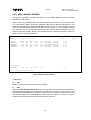
3.6.1. RS232 PORT
Any VT100 compatible video terminal may be plugged into this standard RS232 C serial Port
(see Fig 3.1 for the connector pin assignment). The setting of the Port has to be done in
accordance with the User's terminal characteristics; the Baud Rate and the communication
protocol parameters can be selected via internal DIP switches located on the components
side of the A547 Controller (see Fig. 3.2, Tab. 3.4). A sophisticated Software runs on the
MC68000 microprocessor housed in this module; it acts as a User-friendly interface, to
provide straightforward access:
- to all the channels parameters of the crate directly connected to the terminal;
- to all the channels' parameters of all the crates linked via the H. S. CAENET Network.
In this case the Crate connected directly to the terminal can be used as a H. S.
CAENET Controller (see below).
The default factory configuration of the RS232 Port is listed below.
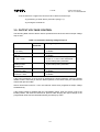
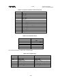
Table 3.3: RS232 Port Default Settings
Password
Baud rate
Number of Stop bits
Parity
The minimum hookup includes pin 2, 3 and 7
Enabled
9600
1
none
pin 7 Signal Ground * *
pin 6 Data Set Ready (in) *
pin 3 TXD Transmit Data
pin 2 RXD Receive Data
pin 1 Ground * *
pin 20 Data Terminal Ready (out)
*
If this line is not connected, Mod SY546
considers it high and will function normally
**
In Mod SY546 pins 1 and 7 are shorted together
Fig. 3.1: RS232 Connector Pin Assignment
15
31/01/96
SY546 User's Manual
Soft. Ver. 0.02 PRELIMINARY
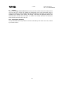
PARITY
PASSWORD EN.
ON (DOT PRESENT)
OFF (DOT NOT PRESENT)
BAUD RATE
SW1
SW2
STOP BIT
SW3
SW4
A547 (COMPONENTS SIDE)
Fig. 3.2: RS232 Parameters Setting
Table 3.4: RS232 Port Settings
Password
Baud rate
Number of Stop bits
Parity
0 (OFF)
Enabled
9600
1
none
16
1 (ON)
Disabled
19200
2
even
31/01/96
SY546 User's Manual
Soft. Ver. 0.02 PRELIMINARY
3.6.2. H. S. CAENET OPERATION
The H. S. CAENET Network is a send and receive half duplex system. It allows
asynchronous serial transmission (1 MBaud rate) of data packets along a simple 50 Ω
coaxial cable. Several devices (H. S. CAENET nodes) are able to share the same media to
transmit and receive data. Each node is able to receive the serial data packet, store it
automatically in a FIFO (RX FIFO) and transmit the data contained in another FIFO (TX
FIFO). Both FIFOs are 512 byte deep.
Usually, the transfers between H. S. CAENET nodes take place according to the typical
Master/Slaves communication:
- there is a single Master, the H. S. CAENET Controller;
- the Slaves are daisy chained on the network, and are identified by an address code
(from 1 to 99);
- the H. S. CAENET Master initiates the transmission, all the Slaves receive the data
and only the addressed Slave accesses the serial line to transmit the data requested
by the Master;
- the maximum data packet length is 512 bytes.
The address of the H. S. CAENET node of the SY546 (Crate #) is selectable via front panel
thumb wheel selector, and its value ranges from 1 to 99. In this way up to 99 crates may be
controlled from a single point in two different ways:
- via a video terminal (the crate directly connected to the terminal is the H. S. CAENET
Controller). In this case, the software allows to operate onto each SY546 in the H. S.
CAENET network as if it is directly connected to the terminal.
- via one of the following H. S. CAENET Controllers:
•
•
•
•
A199HS H. S. CAENET G64 Controller;
A303 H. S. CAENET IBM/PC Controller;
C117B H. S. CAENET CAMAC Controller;
V288 H. S. CAENET VME Controller.
Video terminal and Controllers cannot be used simultaneously.
To avoid reflections it is necessary to terminate the H. S. CAENET line on a 50 Ω
impedance. This is accomplished in the following ways:
- If the H. S. CAENET Controller is one of the crates, by inserting a 50 Ω impedance
terminator in one of the two LEMO 00 type connectors (IN/OUT) in the last and in the first
crate of the chain.
- If the H. S. CAENET Controller is not one of the crates, by inserting a 50 Ω impedance
terminator in one of the two LEMO 00 type connectors (IN/OUT) of the last crate of the
chain.
17
31/01/96
SY546 User's Manual
Soft. Ver. 0.02 PRELIMINARY
4. TERMINAL OPERATION
SOFTWARE VERSION 0.02
A multicrate system can be controlled by a VT100 compatible terminal plugged into the
RS232 port located on the Front Panel as described in § 3.6.
The relevant Software runs on a MC68000 microprocessor housed in the Main Controller
and provides the User with a set of menus that allows to solve most of the problems as
quickly and easily as possible.
The Software allows to control all the Crates on the same H. S. CAENET network and for
each Crate it is possible
- to "kill" all the channels of the Crate;
- to restore the default Factory configuration of all the channel parameters;
- to select the cause and the type of the Alarm;
- to reset the Status output signal;
- to set for each channel a Password protection to avoid an improper channel
parameters setting;
- to program and monitor all the channel parameters described in Chapter 3;
Moreover it is possible for the entire multi-crate system:
- to arrange channels in different Groups;
- to program common parameter values for all the channels belonging to the Group
with a single operation;
- In particular the channels of a Group can be switched ON or OFF simultaneously or
with a programmed sequence in order to obtain the safest ON/OFF detector
procedure;
- It is possible to have up to 16 different Groups. The first Group (GROUP00) contains
all the channels of the Crate.
Figure 4.1 shows the Menu structure of the Software and the parts currently implemented in
the Software Version 0.02.
18
31/01/96
SY546 User's Manual
Soft. Ver. 0.02 PRELIMINARY
Main Menu
Protections
Format
Set/Res.Password
Reformat EEPROM
Crate
Kill
Connect new crate
Kill all channels
Map
Status
Crate Map
Display
Crate Map
Select alarm type
Alarms
Disp./Mod.chann.
Reset alarms
Edit
Edit Parameter
Change
Change Parameter
Group
Group Operation
Add
Insert
Add Channel
Insert Channel
GROUP
Change Group
Name
MENUS
Software version 0.02
Commands
Edit Group
Name
Replace Group
Name
Replace
Replace Channel
Menu currently implemented
Change Group
Parameter
Incr./decr.
Parameter
Fig. 4.1: Terminal Operation Menu Structure
19
31/01/96
SY546 User's Manual
Soft. Ver. 0.02 PRELIMINARY
4.1. MAIN MENU
At Power-On, the logo "C.A.E.N. SY546" appears on the terminal screen; then pressing any
key the top level menu (Main Menu) will appear. The Software Version is indicated on the
top right side of the screen.
A submenu selection can then be made by pressing the key corresponding to the first letter
of the option (highlighted letter).
C.A.E.N.
M A I N
SY546
V0.02
Crate 03
M E N U
Display
Protections
Crate
Map
Kill
Alarms
Status
Format
Quit
Display/Modify channels
Set/Reset password
Connect a new crate
Crate map
Kill all channels
Reset alarms
Select type of alarm
Reformat EEPROM
Abandon program
Select item
Fig. 4.2: Terminal Operation Main Menu
20
31/01/96
SY546 User's Manual
Soft. Ver. 0.02 PRELIMINARY
OPTIONS
D
Display
Display/Modify channels
Shows the status of one or more channels grouped according to symbolic names. Allows
viewing and modifying of the parameters of a single channel or a Group of channels having
a common symbolic name.
P
Protections
Set/Reset password
Protects the System from misuse and allows to disable the front panel Keyboard.
C
Crate
Connect a new Crate
Allows to select which SY546 on the H. S. CAENET network has to be controlled via H. S.
CAENET.
M
Map
Crate Map
Allows to display the Crate configuration.
K
Kill
Kill all channels
All the channels of the Crate are switched off. A confirmation prompt will be displayed and all
channels are shut down at the maximum rate available.
A
Alarms
Reset alarms
Resets the STATUS output signal.
S
Status
Select type of Alarm
Allows to choose the error conditions which cause an Alarm, and the Alarm signal (STATUS
signal) characteristics. The Status command is available only when the Password is
disabled; if the Password is enabled this command is not shown.
F
Format
Reformat EEPROM
This command restores in the permanent memory (EEPROM) the default factory
configuration of the channels' parameter. The Format command is available only when the
Password is disabled; if the Password is enabled this command is not shown (Format sets
the Password to the default factory Password).
Q
Quit
Abandon program
Quits the program and returns to the C.A.E.N. SY546 logo.
21
31/01/96
SY546 User's Manual
Soft. Ver. 0.02 PRELIMINARY
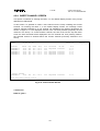
4.2. DISPLAY/MODIFY CHANNELS OPTION
This option is selected by entering the letter "D" in the Main Menu. The screen will show the
parameters' values of the channels of the last Group displayed. If this option is selected on a
Model just shipped from the factory or after a Format command the screen will show the
status of the GROUP00 that contains all the channels present in the Crate. The default
factory configuration of the System is the following:
- the symbolic names of the Groups are GROUP00 .. GROUP15;
- the GROUP00 contains all the channels (the GROUP00 configuration is fixed);
- the other Groups contain no channels.
Each screen contains 16 channels; the remaining channels will be shown on the other pages
by typing the letter "P" (Page command). By entering the letter "M" (More command) the
screen will show the other parameters of the same channels.
On the top of the screen, the following parameters are shown:
- the Group Name;
- the status (ON/OFF) of the "CH_EN" switch;
- the H. S. CAENET address of the connected crate (Crate #);
- the Board Name;
- the Page number.
The Channel parameters shown in this screen depend upon the Board type.
In the first screen, the following parameters are shown for each channel:
Channel, Vmon, Imon, Vset, Iset, Pw, Status, CH#.
In the second screen, the following parameters are shown for each channel:
Channel, SVmax, Rup, Rdwn, Trip, Pon, Password, On/Off, CH#.
Channel is the Channel Name.
Pw (Power) is the status "ON/OFF" of the channel; by setting this parameter On, the
channel is switched On (if the Interlock is not active and the CH EN switch is in the On
position).
SVmax is the Software VMAX (programmable via Local or Remote Control); if the SVmax
programmed value is less then the present VSET value, the VSET takes this value.
22
31/01/96
SY546 User's Manual
Soft. Ver. 0.02 PRELIMINARY
Pon is the Power-On status.
Password is the status of the channel protection.
On/Off is the status of the On/Off channel protection
- If the Password is disabled it is possible to modify every value of the channel
parameters regardless of its Password Parameter.
- If the Password is enabled, the possible actions that can be taken are shown in Table
4.1.
Channel
Password
parameter
"Required"
"Required"
==
Table 4.1: Allowed Operations with Password Enabled
Channel
Action
On/Off
Parameter
"Enabled"
It is possible only to switch ON/OFF the
channel; the other parameters cannot be
modified
==
All the channel parameters cannot be
modified
don't care
it is possible to modify all the channel
parameters except the Password and the
On/Off parameter
The following pages show the structure of the two screens for the GROUP00 and for a
generic Group TEST1 that contains 3 channels. The connected SY546 Crate is in the
following conditions:
- the CH Enable is On;
- the SY546 Crate Number is 01.
On the bottom of the screen are shown some of the available Commands; the User selects
the command by typing the key corresponding to the first letter of the Command itself
(highlighted letter). The highlight bar indicates the Current Parameter and the Current
Channel:
- The Current Parameter is affected by the Modify command shown on the bottom of
the screen (Change/Edit); in particular it is possible to Modify the Channel Name.
- The Current Channel is affected by the Modify Group configuration command shown
on the bottom of the screen (Add, Insert, Replace, Delete); these commands are not
available for GROUP00, because its configuration is fixed.
The Arrow keys allow to move the highlight bar to the parameter that has to be modified.
- The 4 commands Add, Insert, Replace and Delete allow to modify the Group
configuration by adding or removing channels; they are not available for GROUP00
because its configuration is fixed. If the displayed Group does not have any channel,
only the commands Add and Insert are present.
23
31/01/96
SY546 User's Manual
Soft. Ver. 0.02 PRELIMINARY
- The Edit command is available when the Current Parameter can have several values
(Channel, Vset , Iset, SVmax , Rup, Rdwn, Trip).
- The Page command is shown when there are more than 16 channels in the Group.
- The Switch command allows to switch between this screen and the Group operation
screen.
24
31/01/96
GROUP00
Channel
CHANNEL00
CHANNEL01
CHANNEL02
CHANNEL03
CHANNEL04
CHANNEL05
CHANNEL06
CHANNEL07
CHANNEL08
CHANNEL09
CHANNEL10
CHANNEL11
C.A.E.N.
Ch_En is: On
Vmon
0001.60
0001.60
0001.20
0001.60
0002.00
0001.60
0001.60
0001.20
0002.00
0000.60
0000.00
0002.00
SY546
SY546 User's Manual
Soft. Ver. 0.02 PRELIMINARY
V0.02
Crate 03
Imon
0000.00
0000.00
0000.00
0000.00
0000.00
0000.00
0000.00
0000.00
0000.00
0000.00
0000.00
0000.00
Vset
0500.00
0500.00
0500.00
0500.00
0500.00
0500.00
0500.00
0500.00
0500.00
0500.00
0500.00
0500.00
uA
uA
uA
uA
uA
uA
uA
uA
uA
uA
uA
uA
Iset
2500.00
2500.00
2500.00
2500.00
2500.00
2500.00
2500.00
2500.00
2500.00
2500.00
2500.00
2500.00
uA
uA
uA
uA
uA
uA
uA
uA
uA
uA
uA
uA
Pw
Off
Off
Off
Off
Off
Off
Off
Off
Off
Off
Off
Off
Page 0
Status
Ch#
6.00
6.01
6.02
6.03
6.04
6.05
6.06
6.07
6.08
6.09
6.10
6.11
Quit Edit Change Update More Switch
Fig. 4.3: Display of GROUP00, Screen 1, Page 0
GROUP00
Channel
CHANNEL00
CHANNEL01
CHANNEL02
CHANNEL03
CHANNEL04
CHANNEL05
CHANNEL06
CHANNEL07
CHANNEL08
CHANNEL09
CHANNEL10
CHANNEL11
C.A.E.N.
Ch_En is: On
SVmax
2500
2500
2500
2500
2500
2500
2500
2500
2500
2500
2500
2500
Rup
350
350
350
350
350
350
350
350
350
350
350
350
Rdwn
350
350
350
350
350
350
350
350
350
350
350
350
SY546
V0.02
Crate 03
Trip
010.0
010.0
010.0
010.0
010.0
010.0
010.0
010.0
010.0
010.0
010.0
010.0
Pon
Off
Off
Off
Off
Off
Off
Off
Off
Off
Off
Off
Off
Password
Required
On/Off
Enabled
Quit Edit Change Update More Switch
Fig. 4.4: Display of GROUP00, Screen 2, Page 0
25
Ch#
6.00
6.01
6.02
6.03
6.04
6.05
6.06
6.07
6.08
6.09
6.10
6.11
Page 0
31/01/96
TEST01
Channel
CHANNEL03
CHANNEL04
CHANNEL05
CHANNEL06
C.A.E.N.
Ch_En is: On
Vmon
0001.60
0002.00
0001.60
0001.80
SY546
SY546 User's Manual
Soft. Ver. 0.02 PRELIMINARY
V0.02
Crate 03
Imon
0000.00
0000.00
0000.00
0000.00
Vset
0500.00
0500.00
0500.00
0500.00
uA
uA
uA
uA
Iset
2500.00
2500.00
2500.00
2500.00
Pw
Off
Off
Off
Off
uA
uA
uA
uA
Status
Page 0
Ch#
6.03
6.04
6.05
6.06
Quit Edit Change Add Insert Replace Delete Update More Switch
Fig. 4.5: Display of TEST01, Screen 1, Page 0
TEST01
Channel
CHANNEL03
CHANNEL04
CHANNEL05
CHANNEL06
C.A.E.N.
Ch_En is: On
SVmax
2500
2500
2500
2500
Rup
350
350
350
350
Rdwn
350
350
350
350
SY546
V0.02
Crate 03
Trip
010.0
010.0
010.0
010.0
Pon
Off
Off
Off
Off
Password
Required
Required
Required
Required
On/Off
Enabled
Enabled
Enabled
Enabled
Quit Change Add Insert Replace Delete Update More Switch
Fig. 4.6: Display of TEST01, Screen 2, Page 0
26
Ch#
6.03
6.04
6.05
6.06
Page 0
31/01/96
SY546 User's Manual
Soft. Ver. 0.02 PRELIMINARY
COMMANDS
Q
Quit
Returns to Main Menu.
E
Edit
Selects the Edit Parameter Screen. The value of the Current Parameter can be edited and
modified. This command is active when the Current Parameter can have different values
(Channel, Vset, Iset, SVmax, Rup, Rdwn, Trip). It is not active when the Current Parameter
can have only two values (Pw, Pon, Password, On/Off); for these parameters only the
Change command is available.
C
Change
Changes the value of the current parameter.
By entering the "C" key, the value of the Current Parameter is changed:
- if the Current Parameter can have only two different values (Pw, Pon, Password,
On/Off) it toggles between this two values, for example if the Current Parameter is
Pw and its value is Off, by entering "C" the value becomes On and vice versa;
- If the Current Parameter can have different values (Channel, Vset, Iset, SVmax, Rup,
Rdwn, Trip) the display will show the Change Parameter Screen where the previous
value is cleared and a new one has to be typed (the same result is achieved by
pressing one of the numeric keys).
A
Add channel (Command not available for GROUP00)
Selects the Add Channel Screen, that allows to add a channel to the Group.
I
Insert channel (Command not available for GROUP00)
Selects the Insert Channel Screen, that allows to insert a new channel under the Current
Channel in the Group.
R
Replace channel (Command not available for GROUP00)
Selects the Replace Channel Screen, that allows to replace the Current Channel with a
channel to be selected in the Replace Channel screen.
D
Delete channel (Command not available for GROUP00)
Removes the Current Channel from the Group.
U
Update
Refreshes the Screen.
P
Page
Show the next Status page with other 16 channels of the Group, the Page command is
available when there are more than 16 channels in the Group.
M
More
Show the next screen of the same page.
The parameters shown in the two screens are the following:
- screen 1: Channel, Vmon, Imon, Vset, Iset, Pw, Status;
- screen 2 : Channel, Svmax, Rup, Rdwn, Trip, Pon, Password, On/Off.
27
31/01/96
SY546 User's Manual
Soft. Ver. 0.02 PRELIMINARY
S
Switch screen
Selects the Group Operation Screen, from which it is possible:
- to modify the parameters of the entire Group displayed;
- to show the Status of another Group.
To return to the previous screen it is sufficient to enter another time the "S" key.
1, 0 Set a two values parameter
If the Current Parameter can have only two values (Pw, Pon, Password, On/Off) it is
possible to use the keys "1" and "0" to set the two different values (instead of using the "C"
key Change Command). The following table shows the usage of the keys.
Table 4.2: Two Values Parameter Setting
Key
Pw
Pon
Password
On/Off
"0"
"1"
Off
On
Off
On
...
Required
...
Enabled
Numeric keys
- If the Current Parameter can have different values (Vset, Iset, Vmax, Rup, Rdwn, Trip) by
entering the number corresponding to the most significant figure of the new Parameter
value, the display will show the Change Parameter Screen. The corresponding number is
displayed as the most significant figure of the value.
28
31/01/96
SY546 User's Manual
Soft. Ver. 0.02 PRELIMINARY
4.2.1. EDIT PARAMETER SCREEN
This option is selected on entering the letter "E" in the Status Display Screen. In this Screen
it is possible to modify the value of the Current Parameter previously selected.
By pressing the "Edit" key the highlight bar disappears and a blinking cursor appears under
the first character of the value (no command is available on the bottom of the screen). The
cursor indicates the Current Figure of the parameter; the left and right arrow keys move the
cursor along the figures.
On writing a new value and pressing "Return" the Current Parameter will take this new
value; if a "Return" is entered without any change the parameter value remains the same as
the old one.
If the Current Parameter is different from the Channel Name, by using the Up and Down
arrow keys it is possible to increment/decrement the Current Figure:
- pressing the Up arrow key the Current Figure of the Parameter value of all the
channels is incremented by the minimum allowed step;
- pressing the Down arrow key the Current Figure of the Parameter value of all
the channels is decremented by the minimum allowed step.
COMMANDS
Up and Down Arrow keys
Increments/decrements by the minimum allowed step the Current Figure of the Current
Parameter. The cursor indicates the Current Figures.
Ctrl - Z
Clears any modification and restores the old parameter value.
Refer to this paragraph for the usage of the various Edit screens named in the following part of the
chapter:
- Edit Channel Screen;
- Edit Group Name Screen.
29
31/01/96
GROUP00
Channel
CHANNEL00
CHANNEL01
CHANNEL02
CHANNEL03
CHANNEL04
CHANNEL05
CHANNEL06
CHANNEL07
CHANNEL08
CHANNEL09
CHANNEL10
CHANNEL11
C.A.E.N.
Ch_En is: On
SVmax
2500
2500
2500
2500
2500
2500
2500
2500
2500
2500
2500
2500
Rup
350
350
350
350
350
350
350
350
350
350
350
350
Rdwn
350
350
350
350
350
350
350
350
350
350
350
350
SY546
SY546 User's Manual
Soft. Ver. 0.02 PRELIMINARY
V0.02
Crate 03
Trip
010.0
010.0
010.0
010.0
010.0
010.0
010.0
010.0
010.0
010.0
010.0
010.0
Pon
Off
Off
Off
Off
Off
Off
Off
Off
Off
Off
Off
Off
Password
Required
On/Off
Enabled
Required
Required
Required
Required
Enabled
Enabled
Enabled
Enabled
Fig. 4.7: Edit Parameter Screen
(the SVmax of CHANNEL01 is currently edited)
30
Ch#
6.00
6.01
6.02
6.03
6.04
6.05
6.06
6.07
6.08
6.09
6.10
6.11
Page 0
31/01/96
SY546 User's Manual
Soft. Ver. 0.02 PRELIMINARY
4.2.2. CHANGE PARAMETER SCREEN
This option is available in the Status Display Screen when the Current Parameter can have
several values (Channel, Vset, Iset, SVmax, Rup, Rdwn, Trip). It is selected in two ways:
- by pressing the "C" key;
- by entering the number corresponding to the most significant figure of the new value.
In this screen it is possible to enter the new parameter value: by entering the "C" key the
previous value of the Current Parameter is cleared and a new value has to be typed. The
highlight bar disappears, the current parameter value is cleared and a blinking cursor
appears under the first character of the value. If a number has been entered (instead of the
letter "C") the number is displayed as the most significant figure of the value. No commands
are available on the bottom of the screen.
On writing a new value and pressing "Return", the Current Parameter will take this new
value; if a "Return" is entered without any change, the parameter will maintain its old value.
C.A.E.N.
Ch_En is: On
GROUP00
Channel
CHANNEL00
CHANNEL01
CHANNEL02
CHANNEL03
CHANNEL04
CHANNEL05
CHANNEL06
CHANNEL07
CHANNEL08
CHANNEL09
CHANNEL10
CHANNEL11
SVmax
2500
25
2500
2500
2500
2500
2500
2500
2500
2500
2500
2500
Rup
350
350
350
350
350
350
350
350
350
350
350
350
Rdwn
350
350
350
350
350
350
350
350
350
350
350
350
SY546
V0.02
Crate 03
Trip
010.0
010.0
010.0
010.0
010.0
010.0
010.0
010.0
010.0
010.0
010.0
010.0
Pon
Off
Off
Off
Off
Off
Off
Off
Off
Off
Off
Off
Off
Password
Required
On/Off
Enabled
Required
Required
Required
Required
Enabled
Enabled
Enabled
Enabled
Page 0
Ch#
6.00
6.01
6.02
6.03
6.04
6.05
6.06
6.07
6.08
6.09
6.10
6.11
Fig. 4.8: Change Parameter Screen (the SVmax of CHANNEL 01 is in change)
COMMANDS
Ctrl - Z
Clears any modification and restores the old parameter value.
Refer to this paragraph for the usage of the various Change screens named in the following
part of the chapter:
- Change Channel Screen;
- Change Group Name Screen.
31
31/01/96
SY546 User's Manual
Soft. Ver. 0.02 PRELIMINARY
4.2.3. ADD CHANNEL SCREEN
This option is selected on entering the letter "A" in the Status Display Screen of a Group
different from GROUP00.
In this screen it is possible to add a new channel to the current Group. On entering the letter
"A", in the Status Display Screen the message "Add channel" appears followed by a one
channel row displaying the channel parameters as shown in Fig. 4.9. The displayed channel
is the one that follows physically the last channel in the Group. To choose another channel,
the User must use the Up and Down arrow: the other channels will be displayed in the one
channel row, then pressing "Return" the selected channel is added to the Group under the
Current Channel previously selected.
TEST1
Channel
CHANNEL03
CHANNEL04
CHANNEL05
CHANNEL06
C.A.E.N.
Ch_En is: On
SY546
V0.02
Crate 03
SVmax
2500
2500
2500
2500
Rup
350
350
350
350
Rdwn
350
350
350
350
Trip
010.0
010.0
010.0
010.0
Pon
Off
Off
Off
Off
Add channel
CHANNEL07
2500
350
350
010.0
Off
Password
Required
Required
Required
Required
On/Off
Enabled
Enabled
Enabled
Enabled
Page 0
Ch#
6.03
6.04
6.05
6.06
6.07
Quit Help Edit Change Switch
Fig. 4.9: Add Channel Screen
COMMANDS
Q
Quit
Returns to the previous screen without any changes.
E
Edit
Selects the Edit Channel Screen where the Channel Name can be edited and modified; the
highlight bar disappears and a blinking cursor appears under the first character of the value
(no command is available on the bottom of the screen). On writing a new Channel Name
and pressing "Return" the Channel Name will take this new value; if a "Return" is entered
without any change the Name remains the same as the old one.
32
31/01/96
SY546 User's Manual
Soft. Ver. 0.02 PRELIMINARY
C
Change
Selects the Change Channel Screen where the previous Channel Names are cleared and a
new one has to be typed; the highlight bar disappears, the current parameter value is
cleared and a blinking cursor appears under the first character of the value (no command is
available on the bottom of the screen). On writing a new value and pressing "Return" the
Channel Name will take this new value; if a "Return" is entered without a new value the
Name remains the same as the old one.
U/D Up and Down arrow key
The Up and Down arrow keys allow to scroll the channels up and down in the row, ordered
by Channel Number.
33
31/01/96
SY546 User's Manual
Soft. Ver. 0.02 PRELIMINARY
4.2.4. INSERT CHANNEL SCREEN
This option is selected on entering the letter "I" in the Status Display Screen of any Group
different from GROUP00.
In this screen it is possible to insert a new channel into the Group including the Current
Channel. On entering the letter "I" in the Status Display Screen, the message "Insert
channel" appears followed by a one channel row displaying the channel parameters as
shown in Figure 4.10. The displayed channel is the one that precedes physically the last
channel in the Group. To choose another channel, the User must use the Up and Down
arrow: the other channels will be displayed in the one channel row, then pressing "Return"
the selected channel is inserted above the Current Channel previously selected in the
Group.
TEST1
Channel
CHANNEL03
CHANNEL07
CHANNEL04
CHANNEL05
CHANNEL06
C.A.E.N.
Ch_En is: On
SY546
V0.02
Crate 03
SVmax
2500
2500
2500
2500
2500
Rup
350
350
350
350
350
Rdwn
350
350
350
350
350
Trip
010.0
010.0
010.0
010.0
010.0
Pon
Off
Off
Off
Off
Off
Password
Required
On/Off
Enabled
Required
Required
Required
Enabled
Enabled
Enabled
Ch#
6.03
6.07
6.04
6.05
6.06
Insert channel
CHANNEL06
2500
350
350
010.0
Off
Required
Enabled
6.06
Quit Help Edit Change Switch
Fig. 4.10: Insert Channel Screen
COMMANDS
Refer to § 4.2.3
34
Page 0
31/01/96
SY546 User's Manual
Soft. Ver. 0.02 PRELIMINARY
4.2.5. REPLACE CHANNEL SCREEN
This option is selected on entering the letter "R" in the Status Display Screen of any Group
different from GROUP00.
In this screen it is possible to replace the Current Channel with a new channel. On entering
the letter "R" in the Status Display Screen, the message " Replace Channel" appears,
followed by a one channel row displaying the channel parameters of the Current Channel, as
in Fig. 4.11. The displayed channel is the one that follows physically the last channel in the
Group. To choose another channel, the User must use the Up and Down arrow: the other
channels will be displayed in the one channel row, then pressing "Return" the selected
channel replaces the Current Channel previously selected in the Group.
TEST1
Channel
CHANNEL03
CHANNEL06
CHANNEL07
CHANNEL04
CHANNEL05
C.A.E.N.
Ch_En is: On
SY546
V0.02
Crate 03
SVmax
2500
2500
2500
2500
2500
Rup
350
350
350
350
350
Rdwn
350
350
350
350
350
Trip
010.0
010.0
010.0
010.0
010.0
Pon
Off
Off
Off
Off
Off
Password
Required
Required
On/Off
Enabled
Enabled
Required
Required
Enabled
Enabled
Ch#
6.03
6.06
6.07
6.04
6.05
Replace channel
CHANNEL06
2500
350
350
010.0
Off
Required
Enabled
6.06
Quit Help Edit Change Switch
Fig. 4.11: Replace Channel Screen
COMMANDS
Refer to § 4.2.3
35
Page 0
31/01/96
SY546 User's Manual
Soft. Ver. 0.02 PRELIMINARY
4.3. GROUP OPERATION OPTION
The Group Operation Option is selected by entering the "S" key in the Status Display screen
of each Group. A screen appears (Group Operation Screen); within this screen it is
possible:
- to modify the parameters of the entire displayed Group;
- to show the Status of another Group.
To return to the previous screen it is sufficient to enter another time the "S" key.
In the bottom of the screen some of the available commands are shown; the User selects
the command by typing the key corresponding to the first letter of the Command itself.
The left and right Arrow Keys allow to move the highlight bar along the row on the bottom of
the screen. By operating on the fields characterized by the letters "X" it is possible to modify
the corresponding parameter on all the channels (the highlight bar indicates the Current
Parameter: it can be the Group Name, or a field that corresponds to the parameter value of
all the channels).
- If the Current Parameter is the Group Name it is possible to modify it (Change /Edit
command) or to show another Group of channel (using the Replace command or the
Up and Down arrow keys).
- If the Current Parameter can have only two values (Hv, Pon, Password, On/Off) the
keys "1","0" allow to set the two values as shown in § 4.2.
- If the Current Parameter can have different values (Vset, Iset, SVmax, Rup, Rdwn,
Trip) the Change commands allow to enter in the "X" field a value that is taken by all
the channels.
- The Edit commands allow to increment the Current Parameter values of all channels
of the same amount.
- The commands Quit, Page and More have the same usage as in § 4.2.
The Structure of the two screens is shown the following page.
36
31/01/96
GROUP00
Channel
CHANNEL00
CHANNEL01
CHANNEL02
CHANNEL03
CHANNEL04
CHANNEL05
CHANNEL06
CHANNEL07
CHANNEL08
CHANNEL09
CHANNEL10
CHANNEL11
C.A.E.N.
Ch_En is: On
Vmon
0001.60
0001.60
0001.40
0001.60
0002.00
0001.60
0001.60
0001.20
0002.00
0000.60
0000.00
0002.00
SY546
SY546 User's Manual
Soft. Ver. 0.02 PRELIMINARY
V0.02
Crate 03
Imon
0000.00
0000.00
0000.00
0000.00
0000.00
0000.00
0000.00
0000.00
0000.00
0000.00
0000.00
0000.00
Vset
0500.00
0025.00
0500.00
0500.00
0500.00
0500.00
0500.00
0500.00
0500.00
0500.00
0500.00
0500.00
Iset
2500.00
2500.00
2500.00
2500.00
2500.00
2500.00
2500.00
2500.00
2500.00
2500.00
2500.00
2500.00
XXXX.XX
XXXX.XX
uA
uA
uA
uA
uA
uA
uA
uA
uA
uA
uA
uA
GROUP00
uA
uA
uA
uA
uA
uA
uA
uA
uA
uA
uA
uA
Pw
Off
Off
Off
Off
Off
Off
Off
Off
Off
Off
Off
Off
Status
Page 0
Ch#
6.00
6.01
6.02
6.03
6.04
6.05
6.06
6.07
6.08
6.09
6.10
6.11
XXX
Quit Edit Change Replace More Switch
Fig. 4.12: Group Operation Screen of GROUP00, Page 0 (Current Parameter = Group Name)
GROUP00
Channel
CHANNEL00
CHANNEL01
CHANNEL02
CHANNEL03
CHANNEL04
CHANNEL05
CHANNEL06
CHANNEL07
CHANNEL08
CHANNEL09
CHANNEL10
CHANNEL11
GROUP00
C.A.E.N.
Ch_En is: On
SY546
V0.02
Crate 03
SVmax
2500
2500
2500
2500
2500
2500
2500
2500
2500
2500
2500
2500
Rup
350
350
350
350
350
350
350
350
350
350
350
350
Rdwn
350
350
350
350
350
350
350
350
350
350
350
350
Trip
010.0
010.0
010.0
010.0
010.0
010.0
010.0
010.0
010.0
010.0
010.0
010.0
Pon
Off
Off
Off
Off
Off
Off
Off
Off
Off
Off
Off
Off
Password
Required
On/Off
Enabled
Required
Required
Required
Required
Enabled
Enabled
Enabled
Enabled
XXXX
XXX
XXX
XXX.X
XXX
XXXXXXXX
XXXXXXX
Page 0
Ch#
6.00
6.01
6.02
6.03
6.04
6.05
6.06
6.07
6.08
6.09
6.10
6.11
Quit Edit Change Replace More Switch
Fig. 4.13: Group Operation Screen for GROUP00, Page 1 (Current Parameter = Group Name)
37
31/01/96
SY546 User's Manual
Soft. Ver. 0.02 PRELIMINARY
COMMANDS
Q
Quit
Returns to the Main Menu.
E
Edit
This command is active when the Current Parameter is one of the following:
Group Name, Vset, Iset, SVmax, Rup, Rdwn, Trip.
- If the Current Parameter is the Group Name, selects the Edit Group Name Screen.
The value of the Group Name can be edited and modified;
- If the Current Parameter is one of these: Vset, Iset, SVmax, Rup, Rdwn, Trip, it
selects the Increment/Decrement Parameter Screen: the highlight bar disappears,
and a blinking cursor appears under the first "X" of the field that corresponds to the
most significant figure of the Parameter value. The cursor indicates the Current
Figure of the Current Parameter. The left and right arrow keys allow to move the
cursor along the "X" field; and the Up and Down arrow keys allow to
increment/decrement the Current Figure:
- by pressing the Up arrow key the Current Figure of the Parameter value of all
the channels is incremented by the minimum step possible;
- pressing the Down arrow key the Current Figure of the Parameter value of all
the channels is decremented by the minimum step possible.
Then pressing "Return" the display returns to the previous screen.
C
Change
This command is active when the Current Parameter is one of the following:
Group Name, Vset, Iset, SVmax, Rup, Rdwn, Trip.
- If the Current Parameter is the Group Name, selects the Change Group Name
Screen where the Group Name is cleared and a new one has to be typed;
- If the Current Parameter is one of these: Vset, Iset, SVmax, Rup, Rdwn, Trip, selects
the Change Group Parameter Screen: the highlight bar and the "X" disappear, and
a blinking cursor appears under the first position of the field (the same result is
achieved by pressing one of the numeric keys). On writing a new value and pressing
"Return" the Current Parameter of all the channels will take this new value.
R
Replace Group
Selects the Replace Group Screen, which allows to enter the name of the Group to be
displayed. This command is active when the Current Parameter is the Group Name
By entering the letter "R" the highlight bar disappears, the current Group name is cleared
and a blinking cursor appears under the first character of the name. On writing the Name of
another Group and pressing "Return " the screen will show the Group Operation Screen of
this Group (to enter in the Status Display screen of the new Group it is sufficient to press the
"S" key).
38
31/01/96
SY546 User's Manual
Soft. Ver. 0.02 PRELIMINARY
If the typed name does not correspond to one of the existing Groups the screen will prompt
an error message: "The Group <Group Name > is unknown: retry".
P
Page
Shows the next Status page with other 16 channels of the Group. The Page command is
available when there are more than 16 channels in the Group.
M
More
Shows the next screen of the same page of the Group Operation screen:
The parameters shown in the two screens are:
screen 1: Channel, Vmon, Imon, Vset, Iset , Hv, Status;
screen 2: Channel, SVmax, Rup, Rdwn, Trip, Pon, Password, On/Off.
S
Switch screen
Selects the Status display screen of the Group.
1, 0 Set a two values Parameter
If the Current Parameter can have only two values (Hv, Pon, Password, On/Off), the key "1"
and "0" allow to set the two different values. By pressing the keys all the channels take the
same parameter value.
Table 4.3: Two Values Parameter Setting
Key
Hv
Pon
Password
On/Off
"0"
"1"
Off
On
Off
On
...
Required
...
Enabled
U/D
Up and Down arrow key
If the Current Parameter is the Group Name the Up and Down arrow keys allow to select
another Group of channels.
- By pressing the Up key the Group which follows the current Group is selected;
- By pressing the Down key the Group which precedes the current Group is selected.
Numeric keys
- If the Current Parameter can have different values (Vset, Iset, Vmax, Rup, Rdwn, Trip) by
entering the number corresponding to the most significant figure of the new Parameter value
the display will show the Change Group Parameter Screen where the corresponding
number is displayed as the most significant figure of the value.
39
31/01/96
SY546 User's Manual
Soft. Ver. 0.02 PRELIMINARY
4.4. PROTECTION OPTION
This option is selected on entering the letter "P" in the Main menu. If the Password is
enabled the System asks for a password; if the password is correct the "Set Protections"
menu is shown.
Four options can be selected; the User selects the Command by typing the key
corresponding to the first letter of the option itself. They allow:
- to Enable or Disable the Password protection;
- to change the Password itself;
- to disable the Front Panel Keyboard setting.
The meaning of the Password protection is:
- If the Password is enabled:
Channel
Password
parameter
"Required"
Channel
On/Off
Parameter
"Enabled"
"Required"
==
==
Don't care
Action
It is possible only to switch ON/OFF the
channel the other parameters cannot be
modified;
All the channel parameters cannot be
modified;
it is possible to modify all the channel
parameters.except the Password and the
On/Off parameter.
- If the Password is disabled:
- it is possible to modify every value of the channel parameters regardless of the
Password Parameter of the channel;
- in particular it is possible to disable the Password for each channel (the channel
Password is enabled when the word "Required" is shown in the Password field):
- first it is necessary to move the highlighted bar to the Password field;
- when the Password is the Current Parameter, the User has only to type the
"C" key;
- after this operation the Password field becomes blank.
40
31/01/96
SY546 User's Manual
Soft. Ver. 0.02 PRELIMINARY
4.4.1. DISABLE PASSWORD AND KEYBOARD
C.A.E.N.
SY546
V0.02
Crate 03
Set Protections
Change
Change
password
Disable
Disable password
Quit
Abandon program
Select item
Fig. 4.14: Set Protection Menu (Password and Keyboard Enabled)
COMMANDS
Q
Quit
Returns to the Main Menu .
C
Change
Enables to change the Password:
- The System asks for the old Password;
- If the Password is correct then asks for the new Password;
- To confirm the change the System asks for another time the new Password: if the
User doesn't type the new Password the System maintains the old one.
D
Disable
Disables the Password; the screen shows another menu where the "Disable" option is
changed into the "Enable" option;
41
31/01/96
SY546 User's Manual
Soft. Ver. 0.02 PRELIMINARY
4.4.2. ENABLE PASSWORD
C.A.E.N.
SY546
V0.02
Crate 03
Set Protections
Change
Change
password
Enable
Enable password
Quit
Abandon program
Select item
Fig. 4.15: Set Protection Menu (Password Disabled)
COMMANDS
E
Enable
Enables the Password; the screen shows another menu where the "Enable" option is
changed into the "Disable" option.
42
31/01/96
SY546 User's Manual
Soft. Ver. 0.02 PRELIMINARY
4.5. CONNECT A NEW CRATE OPTION
This option is selected on entering the letter "C" in the Main menu. It allows the User to
select which SY546 on the H. S. CAENET Network has to be controlled/monitored via "H. S.
CAENET". If the "C" key is entered, the terminal asks for the number of the crate that the
User wants to control. Near the word "CRATE" the number of the crate physically connected
to the terminal is reported in square brackets.
If the selected Crate can be reached via CAENET, the MAIN MENU will be displayed, and
all the information will refer, from then on, to the crate number indicated on the top right of
the screen. If no SY546 in the network has the entered Crate number, the reply "Remote
crate not responding" will be obtained, and no action will be taken.
C.A.E.N.
M A I N
SY546
V0.02
M E N U
Display
Protections
Crate
Map
Kill
Alarms
Status
Format
Quit
Display/Modify channels
Set/Reset password
Connect a new crate
Crate Map
Kill all channels
Reset alarms
Select type of alarm
Reformat EEPROM
Abandon program
Enter the crate number to be connected
[03]: _
Fig. 4.16: Connect a New Crate Menu
43
Crate 03
31/01/96
SY546 User's Manual
Soft. Ver. 0.02 PRELIMINARY
4.6. CRATE MAP OPTION
This option is selected on entering the letter "M" in the Main menu. It is used to display the
Crate configuration (see figure below).
By entering the "M" key on the display, a screen named "Crate Map" will appear. In ten lines
the ten slots of the crate are reported, indicating the kind of the HV Board inserted in them.
The following Board characteristics are displayed:
- The number of Board channels;
- The Polarity;
- The Maximum Output voltage;
- The Maximum Output Current or the Current reading full scale.
If a slot is empty, the message " Not present" will be displayed. As indicated in the last line, it
is sufficient to press any key to go back to the Main Menu.
C.A.E.N.
SY546
V0.02
Crate 09
Crate map
Slot
Slot
Slot
Slot
Slot
Slot
Slot
Slot
0:
1:
2:
3:
4:
5:
6:
7:
Not Present
Not Present
Not Present
Not Present
BOARD
12 CH
BOARD
12 CH
BOARD
12 CH
BOARD
12 CH
POSITIVE
POSITIVE
NEGATIVE
POSITIVE
6000V
6000V
6000V
6000V
5000.00
5000.00
5000.00
5000.00
Press any key to continue
Fig. 4.17: Crate Map Screen
44
nA
nA
nA
nA
31/01/96
SY546 User's Manual
Soft. Ver. 0.02 PRELIMINARY
4.7. SELECT ALARM MODE OPTION
This option is selected on entering the letter "S" in the Main menu. It allows to choose the
error conditions which cause an Alarm, and the Alarm signal (STATUS signal)
characteristics. The Status command is available only when the Password is disabled.
Five options can be selected:
- the Normal Level of the Alarm signal STATUS (High/Low); this is the STATUS level
when the signal is not active;
- the type of the Alarm signal (Level/Pulsed); if the option chosen is "Pulsed" the
STATUS output (when active) is a periodic signal (the period is about a few hundred
msec);
- a Mask (On/Off) for each of three error conditions (Ovc, Ovv, Unv): if the mask is ON
the corresponding error condition on at least one channel sets the Alarm.
The User selects the Command by typing the key corresponding to the first letter of the
option itself. The option selected toggles between its two values; for example if the Alarm
Type value is "Pulsed", by entering "B" the value becomes "Level" and viceversa.
C.A.E.N.
SY546
V0.02
Crate 03
Select Status Alarm Mode
A)
B)
C)
OVC
OVV
UNV
Q)
Quit
Alarm:
Alarm:
Alarm:
On
Off
Off
Select item
Fig. 4.18: Select Alarm Status Mode Menu
45
31/01/96
SY546 User's Manual
Soft. Ver. 0.02 PRELIMINARY
COMMANDS
A
OVC Alarm
(On/Off)
Selects the Alarm Mask for the Overcurrent condition.
B
OVV Alarm
(On/Off)
Selects the Alarm Mask for the Overvoltage condition.
C
UNV Alarm
(On/Off)
Selects the Alarm Mask for the Undervoltage condition.
Q
Quit
Returns to the Main Menu.
5. H. S. CAENET OPERATION
The Model SY546 is provided with a H. S. CAENET node through which it can be controlled
by the following H. S. CAENET Controllers:
Mod. C117B
Mod. V288
Mod. A199HS
Mod. A303
- H. S. CAENET CAMAC Controller;
- H. S. CAENET VME Controller;
- H. S. CAENET G64 Controller;
- H. S. CAENET PC Controller.
NOTE: the Address Number of the SY546 (Crate #) must be the only one in the line in
which you wish to insert the module. It can be any number between 1 and 99. Due to
high transmission speed of the data in line it is necessary to terminate this line on a
50 Ω impedance at the end to avoid reflections.
Via H. S. CAENET it is possible to modify all the channel parameters regardless of its
Password Protection Status (enabled/disabled) selected via Terminal (see § 5.2 and 5.4). In
particular it is possible to modify the status of its Password Parameter.
5.1. USING THE H. S. CAENET VME CONTROLLER
The Mod. SY546 can be controlled remotely via VME through the Mod. V 288 H. S.
CAENET VME Controller.
The Model V288 has been designed to control a H. S. CAENET node through the VME bus.
It is composed of a collection of registers, for the operation control, and two memory buffers
for the transmitted and received data packets, arranged in a FIFO logic 16 bit wide 256 word
deep.
In the memory buffer for the received data are also stored some error messages generated
by the V288 itself when the H. S. CAENET operation has failed (see Table 5.15).
46
31/01/96
SY546 User's Manual
Soft. Ver. 0.02 PRELIMINARY
Standard VME cycles allow the User to perform the required control and setting operations
on each Mod. SY546 in the network, according to the typical MASTER/SLAVE
communication protocol, where the VME controller assumes the MASTER function.
The module operations can be software controlled in polling mode or can be handled via
interrupt facility. It houses a VME ROAK INTERRUPTER that generates a VME interrupt (if
enabled) as soon as the data packet (or the error message) is stored in the receive buffer.
The Mod. V288 registers are described in Table 5.1
47
31/01/96
SY546 User's Manual
Soft. Ver. 0.02 PRELIMINARY
Table 5.1: Mod. V288 Registers
NAME
TYPE
ADDRESS
FUNCTION
Transmit Data Buffer
Receive Data Buffer
Status Register
Write only
Read only
Read only
Base Address + 00
Base Address + 00
Base Address + 02
Transmission Register
Write only
Base Address + 04
Reset Register
Interrupt Vector Register
Write only
Write only
Base Address + 06
Base Address + 08
Transmit data storage
Receive data storage
After a H. S. CAENET
operation
has
been
performed, this register
indicates
whether
the
operation is valid or not;
FFFE=
valid
operation
FFFF= no valid operation
By writing into this register
the Transmit Data buffer
content is transmitted on the
cable
Module's Reset
Interrupt vector programming register
5.1.1. TRANSMIT DATA BUFFER
(Base Address + 0, write access)
This is the buffer which is loaded with the data packet to transmit. It is arranged in a FIFO
logic 16 bit wide (the transmitted data packet is composed of 16 bit words as shown in Tab.
5.2).
5.1.2. RECEIVE DATA BUFFER
(Base Address + 0, read access)
This is the buffer where the Mod.V288 automatically stores the data packet received from
the SY546 or, if the H. S. CAENET operation has failed, stores an error code. It is arranged
in a FIFO logic 16 bit wide (the data packet received is composed of 16 bit words as shown
in Tab. 5.3).
5.1.3. STATUS REGISTER
(Base Address + 2, read only)
The content of this register indicates if the previous H. S. CAENET operation is valid or not.
Status Register = %FFFF ⇒ No valid operation;
Status Register = %FFFE ⇒ Valid operation.
After one of the following operations the User is recommended to read the Status Register:
- write data in the Transmit Data buffer: it indicates if the datum written has been
stored or not in the Transmit Data Buffer; a "No valid operation" means that the
Transmit Data Buffer is not available for data storage. This may happen in these
cases:
48
31/01/96
SY546 User's Manual
Soft. Ver. 0.02 PRELIMINARY
- if the H. S. CAENET node is active (it is transmitting a previous data packet or
it is receiving the Slave response data packet);
- if the Transmit Data Buffer is full (the max. number of stored data is 256);
- write in the Transmission Register (Start data packet transmission): it indicates if
the Start Transmission command has been recognized by the Mod. V288; a "No valid
operation" means that the H. S. CAENET node is not able to transmit data. This may
happen if the H. S. CAENET node is active (it is transmitting a previous data packet
or it is receiving the Slave response);
- read data from the Receive Data Buffer: it indicates if the data read is valid or not.
5.1.4. TRANSMISSION REGISTER
(Base Address + 4, write only)
By writing at this location the H. S. CAENET node enters in the transmit mode: the data
stored in the Transmit Data Buffer are transmitted on the cable. If this operation is performed
with the Transmit Data Buffer empty, an error message is stored in the Receive Data Buffer
(error %FFFD, see Table 5.15).
5.1.5. RESET REGISTER
(Base address + 6, write only)
A write access to this location causes the V288 to enter in restart mode; this causes the
following operations:
- the buffers are cleared;
- every pending interrupt is cleared;
- every data transfer is aborted;
- the V288 does not accept any command.
It remains in this status for about 3 msec. The module can be reset also by pressing the
Front Panel Push button.
5.1.6. INTERRUPT VECTOR REGISTER
(Base address + 8, write only)
The value written in this 8 bit register is the STATUS/ID that the V288 INTERRUPTER
places on the VME data bus during the Interrupt Acknowledge Cycle.
5.1.7. V288 ADDRESSING CAPABILITY
The module works in A24 mode; this implies that the module address must be specified in a
field of 24 bits.
The Address Modifiers used by the module are:
AM
= %39 :
Standard User data access
AM
= %3A :Standard User program access
AM
= %3D :
Standard supervisor data access
AM
= %3E :Standard supervisor program access
49
31/01/96
SY546 User's Manual
Soft. Ver. 0.02 PRELIMINARY
The module's Base Address is fixed by dip switches located on the board (see V288
Technical Information Manual Fig. 4.1)
5.1.8. V288 DATA TRANSFER AND INTERRUPTER CAPABILITY
The registers and the buffers are accessible in D16 mode.
The V288 module houses a VME ROAK INTERRUPTER D08(o) type. This implies the
following:
- it responds to 8 bit, 16 bit and 32 bit interrupt acknowledge cycles providing an 8-bit
STATUS/ID on the VME data lines D00..D07.
- it removes its interrupt request when the VME MASTER reads the V288 STATUS/ID
during the Interrupt Acknowledge Cycle (ROAK: Release On Acknowledge).
5.1.9. V288 INTERRUPT LEVEL
The interrupt level corresponds to the value set on the two dip-switches SW4, SW3 as
described in the V288 Technical Information Manual .
5.1.10.
MASTER-TO-SLAVE DATA COMPOSITION (V288 CASE)
The Master-to-Slave data have to be written in the Transmit Data Buffer, by performing
subsequent write accesses as follows.
Table 5.2: Master-to-Slave Data Composition
Order
Operation
Address
Datum
(HEX)
Meaning
1
Write
Base Ad. + 0
%0001
2
3
Write
Write
Base Ad + 0
Base Ad + 0
%00XX
Code
4 to 256
Write
Base Ad + 0
Code/Set
H.
S.
CAENET
Controller identified
code
Crate Number
First word of the
operation Code(*) to
be performed
Eventual subsequent
words of the Code or
Set values
(*) The operation Codes may be some words in length and eventually followed by several set values.
In the SY546 case the Code may be one or two words in length.
As soon as the data packet has been stored in the Transmit Data Buffer, it can be
transmitted on the cable by performing a Write operation on the Transmission Register. The
operation codes are shown in Tab. 5.8.
After any transmission, in the V288 Receive Data Buffer the User reads the Slave response
or a V288 error message (for example if the V288 does not receive any Slave response
50
31/01/96
SY546 User's Manual
Soft. Ver. 0.02 PRELIMINARY
within a period of 500 msec it stores the code %FFFF in the Receive Data Buffer, see Table
5.15).
5.1.11.
SLAVE-TO-MASTER DATA COMPOSITION (V288 CASE)
The answer data coming from the Mod. SY546 or a Mod. V288 error message is
automatically stored into the V288 Receive Data buffer and therefore is available to the
User. As soon as the data pack is stored in this buffer, a VME interrupt (if enabled) is
generated.
The following Table shows the structure of the SY546 data packet:
Table 5.3: Slave-to-Master Data Composition
Order
1
2 to 255(*)
Operation
Read
Read
Address
Base Ad + 0
Base Ad + 0
Datum
Error Code
value
Meaning
Error code
Eventual Parameter value
(*) The first data of the packet is read and checked by the V288 Control Logic (see V288 Tecnical
Information Manual).
The Error Codes are described in Tab. 5.14.
51
31/01/96
5.1.12.
SY546 User's Manual
Soft. Ver. 0.02 PRELIMINARY
V288 - SY546 COMMUNICATION SEQUENCE
- write the data packet in the Transmit Data Buffer; in the packet is contained the H. S.
CAENET address of the SY546 (Crate #) (see Tab. 5.2 for the data structure).
For each data:
- write the data in the Transmit Data Buffer;
- read the Status Register;
- if Status Register =%FFFE
{
the data is stored in the buffer
}
- else
{
error
}
- Transmit the data packet:
- Access in write the Transmission Register;
- read the Status Register;
- if Status Register = %FFFE
{
the V288 H. S. CAENET Node enters in the transmit mode and the data
packet stored is transmitted on the cable
}
- else
{
error
}
- Wait for the SY546 response
- if the Interrupt is enabled
{
wait for V288 interrupt
}
- else
{
- read the Receive data buffer;
- read the Status Register;
- if Status Register = %FFFF discard the data and repeat the two read
operations;
- if Status Register = %FFFE accept the data read: it may be the first data of
the SY546 response data packet or a V288 error message; go to the Read
Response section;
}
- Read response
- read the Receive data buffer;
- read the Status Register;
- if Status Register = %FFFE accept the data read and repeat the two read operation;
- if Status Register = %FFFF discard the data read and exit: the Receive Data Buffer is
empty.
52
31/01/96
SY546 User's Manual
Soft. Ver. 0.02 PRELIMINARY
5.2. USING THE H. S. CAENET CAMAC CONTROLLER
The Mod. SY546 can be controlled remotely via CAMAC through the Mod. C 117B, H. S.
CAENET CAMAC Controller.
The Model C 117B has been designed to control a H. S. CAENET node through the CAMAC
bus. It houses two memory buffers for the transmitted and received data packets, arranged
in a FIFO logic 16 bit wide 256 word deep.
In the memory buffer for the received data are also stored some error messages generated
by the C117B itself when the H. S. CAENET operation has failed (see Table 5.15).
The standard CAMAC functions listed in Table 5.4 allow the User to perform the required
control and setting operations on each Mod. SY546 in the network according to the typical
MASTER/SLAVE communication protocol, where the CAMAC controller assumes the
MASTER function.
As soon as the data packet (or the error message) is stored in the receive buffer, a LAM
signal is generated (if enabled).
X response is generated for all valid function.
Q response is generated for each valid function unless is otherwise specified (see Table
below).
Table 5.4: Mod. C 117 B CAMAC Functions
F(0) N
F(8) N
F(9) N
F(16) N
F(17) N
F(24) N
F(26) N
C, Z
Reads the data stored in the Mod. C117B
Receive Data buffer. Q response while the
buffer contains data.
Tests the LAM line. Q response if LAM is
true.
Resets the module (clears buffer and LAM;
disables the LAM line).
Stores the data into the Mod. C117B
Transmit Data buffer. Q response until the
buffer is full (256 16-bit words).
Transfers data to the serial line.
Disables the LAM line.
Enables the LAM line.
Same as F(9) N.
53
31/01/96
SY546 User's Manual
Soft. Ver. 0.02 PRELIMINARY
5.2.1. TRANSMIT DATA BUFFER [F(16) N FUNCTION]
This is the buffer which is loaded with the data packet to transmit; it is arranged in a FIFO
logic 16 bit wide (the transmitted data packet is composed of 16 bit words as shown in Tab.
5.5). The data are stored in this buffer by performing one or more F(16) N Functions with the
data to be written asserted on the WRITE lines W<1..16>.
The Q response to the F(16) N Function indicates if the datum has been stored or not in the
Transmit Data Buffer;
- Q=1 means that the data has been stored in the Transmit Data Buffer;
- Q=0 means that the Transmit Data Buffer is not available for data storage. This may
happen in these cases:
- if the H. S. CAENET node is active (it is transmitting a previous data packet or
it is receiving the Slave response data packet);
- if the Transmit Data Buffer is full (the maximum number of data stored is 256)
5.2.2. RECEIVE DATA BUFFER [F(0) N FUNCTION]
This is the buffer where the Mod. C117B automatically stores the data packet received from
the SY546 or, if the H. S. CAENET operation has failed, stores an error code. It is arranged
in a FIFO logic 16 bit wide (the received data packet is composed of 16 bit words as shown
in Tab. 5.6). The data contained in the Receive Data buffer are read by performing F(0) N
Functions. The required data are present on the READ lines R<1..16>.
The Q response indicates if if the data read is valid or not:
- Q=1 ⇒ valid data;
- Q=0 ⇒ no valid data.
5.2.3. START TRANSMISSION [F(17) N FUNCTION]
By performing an F(17) N Function the H. S. CAENET node enters in the transmit mode: the
data stored in the Transmit Data Buffer are transmitted on the cable. If this operation is
performed with the Transmit Data Buffer empty, an error message is stored in the Receive
Data Buffer (error %FFFD see Table 5.15).
The Q response indicates if the Start Transmission command has been recognized or not by
the Mod. C117B;
- Q=1 ⇒ the Transmit command has been successfully recognized and that a valid
response can be read in the Receive Data Buffer within a period of 500 msec.(the
C117 waits up to 500 msec for a Slave response, after this it stores in the Receive
Data Buffer the error code %FFFF, see Table 5.15)
- Q=0 ⇒ the H.S CAENET node is not able to transmit data. This may happen if the H.
S. CAENET node is active (it is transmitting a previous data packet or it is receiving
the Slave response).
54
31/01/96
SY546 User's Manual
Soft. Ver. 0.02 PRELIMINARY
5.2.4. C117B RESET
The C117 B can be resetted in the following ways:
- by performing an F(9) N Function;
- by performing a C Command;
- by performing a Z Command;
- by pushing the Front Panel push button.
After one of these operations the C117B enters in restart mode; this causes the following:
- the buffers are cleared;
- the LAM is cleared;
- the LAM is disabled;
- every data transfer is aborted;
- the C117B does not accept commands.
It remains in this status for about 3 msec.
5.2.5. MASTER-TO-SLAVE DATA COMPOSITION (C117B CASE)
The MASTER-to-SLAVE data have to be written into the Transmit Data buffer by performing
subsequent F(16) N functions as follows:
Table 5.5: Master-to-Slave Data Composition
Order
CAMAC
Function
W16 to W1
(HEX)
Meaning
1
F(16) N
%0001
2
3
F(16) N
F(16) N
%00XX
Code
4 to 256
F(16) N
Code/Set
H. S. CAENET Controller
identified code
Crate Number
First word of the operation
Code(*) to be performed
Eventual subsequent words
of the Code or Set values
(*) The operation Codes may be some words in length and eventually followed by several set values.
In the SY546 case the Code may be one or two words in length.
After the required F(16) N functions have been performed, it is necessary to carry out an
F(17) N function in order to transfer the stored data to the addressed module. The operation
codes are shown in Tab. 5.8.
As soon as the response data packet is stored into the C117B Receive Data Buffer a LAM
signal is generated (if enabled). The LAM is cleared whenever the last datum has been read.
If the LAM has not been enabled after the F(17) N function the F(0) N function must be
repeated until a Q=1 response is obtained. The readout is over when Q=0 (Q STOP readout
operation).
55
31/01/96
SY546 User's Manual
Soft. Ver. 0.02 PRELIMINARY
In the C117 B Receive Data Buffer the User reads the SY546 response or a C117 B error
message (for example if the C117 B does not receive any Slave response within a period of
500 msec it stores the code %FFFF in the Buffer, see Tab. 5.15).
5.2.6. SLAVE-TO-MASTER DATA COMPOSITION (C117B CASE)
The answer data coming from the Mod. SY546 or a Mod. C 117 B error message is
automatically stored into the C117 B Data buffer and therefore is available to the User. As
soon as the data pack is stored in this buffer, a LAM (if enabled) is generated.
The following Table shows the structure of the SY546 data packet:
Table 5.6: Slave-to-Master Data Composition
Order
CAMAC
Function
Datum
Meaning
1
2 to 255(*)
F(0) N
F(0) N
Error Code
value
Error code
Eventual Parameter
value
(*) The first data of the packet is read and checked by the C117B Control Logic (see C117B Technical
Information Manual).
The Error codes are described in Tab. 5.14.
56
31/01/96
SY546 User's Manual
Soft. Ver. 0.02 PRELIMINARY
5.2.7. C117B - SY546 COMMUNICATION SEQUENCE
- write the data packet in the Transmit Data Buffer; in the packet is contained the H. S.
CAENET address of the SY546 (Crate #) (see Tab. 5.5 for the data structure).
For each data:
- perform an F(16) N Function;
- if Q=1
{
the data is stored in the buffer
}
- else
{
error
}
- Transmit the data packet:
- perform an F(17) N Function;
- if Q=1
{
the C117B H. S. CAENET Node enters in the transmit mode and the data
packet stored is transmitted on the cable
}
- else
{
error
}
- Wait for the SY546 response
- if LAM is enabled
{
wait for C117B LAM: when LAM is asserted go to the Read response section
}
- else
{
- perform an F(0) N Function;
- if Q=0 discard the data and repeat the operation;
- if Q=1 accept the data read: it may be the first data of the SY546 response
data packet or a C117B error message; go to the Read Response section
}
- Read response
- perform an F(0) N Function;
- if Q=1 accept the data read and repeat the operation;
- if Q=0 discard the data read and exit: the Receive Data Buffer is empty.
57
31/01/96
SY546 User's Manual
Soft. Ver. 0.02 PRELIMINARY
5.3. MASTER-TO-SLAVE DATA PACKET DESCRIPTION
The MASTER-to-SLAVE data packet described in the § 5.1.1 and 5.2.5 has the following
structure:
Table 5.7: Master-to-Slave Data Composition
Order
Datum (Hex)
1
2
3
%0001
%00XX
Code
4 to 256
Code/Set
Meaning
H. S. CAENET Controller identified code
Crate Number
First word of the operation Code to be
performed
Eventual subsequent words of the Code or set
values
In the following Table are shown the various Data packet available.
Table 5.8: Data Packet
word 3
word 4
Meaning
%0
%3
%5
%1A
==
==
==
Alarm Word
Boards identifier
Read Boards characteristics
Read General Status
Set Alarm Status
%30
%31
%32
%35
%36
%n01
%n02
%n10
%n12
%n14
%n15
%n16
%n17
%n18
%n19
Format CPU EEPROM
Confirm Format CPU EEPROM
Clear Alarm
Kill All Channels
Confirm Kill All Channels
==
==
Read Channel n Status
Read Channel n parameters values
Vset value
Set Channel n Vset value
Iset value
Set Channel n Iset value
Vmax soft. value Set Vmax software value
Rup value
Set Channel n Ramp-up value (Rup)
Rdwn value
Set Channel n Ramp-down value
(Rdwn)
Trip value
Set Channel n Trip value
Mask & Flag Set Channel n Flags values (Pon,
On/Off, Password, Power)
Channel
Set Channel n name
Name *
- n = Channel's physical number on the Board (n = %00..%5F, corresponding to
channels 0 to 95).
58
31/01/96
* : 6 words (word 4 to 9, see § 5.3.3).
59
SY546 User's Manual
Soft. Ver. 0.02 PRELIMINARY
31/01/96
SY546 User's Manual
Soft. Ver. 0.02 PRELIMINARY
5.3.1. PARAMETERS SETTING
The set parameters (Vset, Iset, and so on) must be expressed in the following
units (for the Vdec, Idec, Current Unit description see §5.4.3):
Table 5.9: Parameters Units
Parameter
Units
Volt x 10Vdec
Current Units x 10Idec
Volt
Volt/sec
Volt/sec
arbitrary value
Vset value
Iset value
Vmax soft. value
Rup value
Rdwn value
Trip value
5.3.2. MASK & FLAG SETTING
The Mask bits indicate which parameter must be modified; the Flag bits indicate which value
the parameters must assume:
- if Mask bit =0
- if Mask bit =1
the corresponding parameter maintains the old value;
The corresponding parameter will take the value
indicated in the corresponding Flag bit.
The following Table shows the structure of the Mask & Flag word.
Table 5.10: Mask & Flag Word Structure
Bits
Meaning
0..2
3
4
5
6
7
8..10
11
12
13
14
15
Don't care
H.V. flag
Password flag
Don't care
On/Off flag
Pwon flag
Don't care
Mask Power
Mask Password
Don't care
Mask On/Off
Mask Pwon
The correspondence of the Flag bits values with the Parameters values is shown in the
following Table.
60
31/01/96
SY546 User's Manual
Soft. Ver. 0.02 PRELIMINARY
Table 5.11: Flag bits and Parameters Values
Flag bit
"0"
"1"
Power
Pon
Password
On/Off
Off
On
Off
On
...
Required
...
Enabled
Note that the channel Password parameter can be modified regardless of the Password
protection Status (enabled/disabled) selected via Terminal (see § 4.4).
5.3.3. CHANNEL NAME SETTING
The CAENET operating code %n19 allows to set the Channel Name up to 11 characters
followed by the null terminator 0. The structure of the Words, assuming, e. g., that
"ABCDEFGHIJK" is the Channel Name, is the following:
Word
4
5
6
7
8
9
Content
"A", "B"
"C", "D"
"E", "F"
"G", "H"
"I", "J"
"K", 0
- If there are less than 11 characters, the name is completed with a pad of zeroes. If there
are more than 11 characters, the response is an error code %FF01. If the 0 terminator is
missing, or if "spurious" characters are used (e.g. "@", "?", etc., the response is an error
code %FF02.
5.3.4. ALARM STATUS SETTING
The CAENET operating code %1A (followed by a Word) allows to set the Status of the
Alarms. The structure of the Word is the following:
Alarm Status Word Structure
Bits
0
1
2
3..15
Bit value = 0
OVC Alarm OFF
OVV Alarm OFF
UNV Alarm OFF
Don't care
61
Bit value = 1
OVC Alarm ON
OVV Alarm ON
UNV Alarm ON
Don't care
31/01/96
SY546 User's Manual
Soft. Ver. 0.02 PRELIMINARY
5.3.5. SYSTEM OPERATIONS
The CAENET operating codes include the following "System" operations.
Codes %30, %31 (Format CPU E2PROM)
- The CAENET operating codes %30, %31 allow to format the CPU EEPROM. In order
to do this a CAENET command %30 must be performed, followed by a %31
command to confirm the operation. If only a %31 is performed, the response is an
error code %FF01.
Code %32 (Clear Alarm)
- The CAENET operating code %32 clears the Alarms occurred in the System.
Codes %35, %36 (Kill All Channels)
- The CAENET operating codes %35, %36 allow to kill all channels. In order to do this
a CAENET command %35 must be performed, followed by a %36 command to
confirm the operation. If only a %36 is performed, the response is an error code
%FF01.
62
31/01/96
SY546 User's Manual
Soft. Ver. 0.02 PRELIMINARY
5.4. SLAVE-TO-MASTER DATA PACKET DESCRIPTION
The answer data coming from the Mod. SY546 or from the H. S. CAENET Controller has the
following structure.
Table 5.12: Slave-to-Master Data Composition
Order
Datum (HEX)
1
2 to 25
Meaning
Error Code
value
Error code
Eventual Parameter
value
5.4.1. ERROR CODES DESCRIPTION
The Error codes are described in the following Table.
Table 5.13: Error Codes
Datum
(Hex)
%0
%FF00
%FF01
%FF02
%FF03
%FFFD
%FFFE
%FFFF
Meaning
Successful operation.
Module Busy; it has tried to effect an operation while the module is
performing a previous operation.
Code not recognized or message incorrect.
Value out of range.
Channel or Board not present.
No data to be transmitted; it has tried to start a transmission with
the Transmit data Buffer empty (H. S. CAENET Controller error
message).
The H. S. CAENET Controller identifier is incorrect (H. S. CAENET
Controller error message).
The addressed module does not exist. This message are generated
after a period of 500 msec (H. S. CAENET Controller error
message).
63
31/01/96
SY546 User's Manual
Soft. Ver. 0.02 PRELIMINARY
5.4.2. MODULE IDENTIFIER PACKET
(Response To Code %0)
The response contains in the low byte the ASCII code of the string of characters identified by
the name of the Module plus the version of the software running on the Main Controller.
Table 5.14: Module Identifier Data Packet Structure
Word
2
3
4
5
6
7
8
9
10
11
12
Contents
db15..8
db7..0
0
"S"
0
"Y"
0
"5"
0
"4"
0
"6"
0
""
0
"V"
0
"0"
0
"."
0
"0"
0
"2"
64
31/01/96
SY546 User's Manual
Soft. Ver. 0.02 PRELIMINARY
5.4.3. BOARD CHARACTERISTICS PACKET
(Response To Code %3)
The Response contains the characteristics of the Boards inserted in the System Mainframe
by sending 8 identical packets (one per board). The structure of each packet is described in
Table 5.15.
Table 5.15: Board Parameters Packet Structure
Word
2
3
4
5..24
25
26
27
28
29
30
31
Contents
db15..0
Current units
Vmax software
Imax software
Reserved
Rampmin
Vres
Ires
Vdec
Idec
Polarity
Board Present
Current Units:
The Iset, Imon unit is indicated by this byte:
= 0:
= 1:
= 2:
= 3:
Ampere
mA
µA
nA
Vmax<15..0>:
This word indicates the Maximum Output Voltage of the Board channels expressed in Volt.
Imax<15..0>:
This word indicates the Maximum Output Current of the Board channels, it is expressed in
(Current Units)/10Idec.
Maximum Output Current (expressed in Current Units) = Imax * 10-Idec
Rampmin<15..0>:
This word indicates the Minimum Ramp-Up/Down value programmable for the channels of
the Board expressed in Volt/sec.
Vres<15..0>:
This word indicates the Vset/Monitor resolution for the Board expressed in hundredth of Volt.
Ires<15..0>:
This word indicates the Iset/Monitor resolution for the Board expressed in hundredth of the
unit determined via the Current Unit field.
65
31/01/96
SY546 User's Manual
Soft. Ver. 0.02 PRELIMINARY
Vdec<15..0>:
This word indicates the No. of significant figures after the decimal point for Vset/Monitor of
the Board channels.
Idec<15..0>:
This word indicates the No. of significant figure after decimal point for Iset/Monitor of the
Board channels.
Polarity:
This word indicates the polarity of the board. It can be 1 (positive polarity) or 0 (negative
polarity).
Board present:
This word indicates the presence of the board. It can be 1 (board present) or 0 (board not
present).
5.4.4. GENERAL STATUS PACKET
(Response To Code %5)
The CAENET operating code %5 allows to read the General Status. The System provides in
response two Words: the first is the Alarm Status Word, the second contains the following
information:
Bits
0
1
2
3
4
5
6
7
8..15
Status Signals Word Structure
Bit value = 0
Bit value = 1
No HV Enable
HV Enable
Password can be Enabled
Password is Disabled
Baud Rate = 9600
Baud Rate = 19200
1 Stop Bit
2 Stop Bits
No Parity
Even Parity
Don't care
Don't care
Don't care
Don't care
No External Kill Present
External Kill Present
Don't care
Don't care
66
31/01/96
SY546 User's Manual
Soft. Ver. 0.02 PRELIMINARY
5.4.5. CHANNEL STATUS PACKET
(Response To Code %n01)
The response content is shown in the following Table.
Table 5.16: Channel Status Data Packet Structure
Word
Contents
2
3
4
5
Vmon<31..16>
Vmon<15..0>
Imon<15..0>
Status<15..0>
The values of Vmon, HVmax ad Imon are expressed in the following units:
Table 5.17: Parameters Units
Parameter
Units
Volt / 10Vdec
Current Units / 10Idec
Vmon
Imon
The word 5 (Status) contains the status of the Channels as shown bellow
Table 5.18: Channel Status
Bits
0
1.. 7
8
9
10
11
12
13
14
15
bit value = 0
bit value = 1
Channel not Present;
Don't care
Channel present
Don't care
Vmax
Trip
Overvoltage
Undervoltage
Overcurrent
Down
Up
Channel On
Channel Off
5.4.6. CHANNEL PARAMETERS PACKET
(Response To Code %n02)
The words 2 to 7 represent a field that contains the Channel Name as a string. It
accommodates the characters of the Channel Name followed by the null terminator 0 which
marks the end of the string (only the bytes that precede the 0 are valid data, the bits from the
0 to end of the field are meaningless; see Table 5.19, where the Channel name is
"TESTCH1").
67
31/01/96
SY546 User's Manual
Soft. Ver. 0.02 PRELIMINARY
Table 5.19: Channel Parameters Packet Structure
Word
Contents
2
3
4
5
6..7
8
9
10
11
12
13
14
15
"T", "E"
"S", "T"
"C", "H"
"1", 0
don't care
Vset<31..16>
Vset<15..0>
Iset<15..0>
Vmax software <15..0>
Rup<15..0>
Rdwn<15..0>
Trip<15..0>
Flag
Table 5.20: Parameters Units
Parameter
Units
Volt / 10Vdec
Current Units / 10Idec
Volt
Volt/sec
Volt/sec
arbitrary value
Vset
Iset
Vmax soft.
Rup
Rdwn
Trip
The word 15 contains the values of the channel flags
Table 5.21: Flag Structure
Bits
Bit value= 0
Bit value =1
0..10
11
12
13
14
15
Don't care
Power= Off
Password =" "
Reserved
On/Off = ".."
Pwon = Off
Don't care
Power = On
Password ="Required"
Reserved
On/Off= "Enabled"
Pwon = On
68
31/01/96
SY546 User's Manual
Soft. Ver. 0.02 PRELIMINARY
5.4.7. PARAMETERS SETTING SLAVE RESPONSE
After a Set Command the SY546 responds in the following way:
- If the Set operation is correct it responds with an error code = 0, and it is Busy for
about 20 msec;
- If it is Busy (for a preceding Set operation) it responds with an error Code = %FF00
Module Busy.
APPENDIX A: SOFTWARE EXAMPLES (A303 USERS)
The details of using the Mod. A303 to communicate with the Mod. SY546 are explained by
means of complete examples:
- PCCAENET.H:
Declaration for the communication with the Mod. A303
- CAENCNT.C :
Caenet Package for the A303 Module
These two listings describe the functioning and general design of a driver for the Mod A303;
all the possible errors are handled.
- PCSY546.C :
Demonstration on the use of Caenet Routines in communication
between A303 and SY546
This example is to be used as a guideline in creating a communication software between the
A303 and the SY546 module.
69
31/01/96
SY546 User's Manual
Soft. Ver. 0.02 PRELIMINARY
/**********************************************************************/
/*
*/
/*
-----C. A. E. N.
S.p.A.
-----*/
/*
*/
/*
PCCAENET.H
*/
/*
Questo file fa parte del progetto CAENET.PRJ.
*/
/*
Contiene le macro e le dichiarazioni che servono ai programmi
*/
/*
che vogliano colloquiare col Caenet tramite l'A303
*/
/*
*/
/*
*/
/*
Creato il 2 Luglio 1991
*/
/*
Aggiunte le dichiarazioni delle funzioni per la gestione
*/
/*
dell'A303 come Slave il 29 Agosto 1991
*/
/*
*/
/*
Aut: C.Raffo
*/
/*
*/
/**********************************************************************/
/*
Indirizzi dei registri dell'A303 come offset di "address"; quest'ultimo
rappresenta l'indirizzo dell'A303 nella mappa di memoria del PC.
Il valore di default e' D001:0000
*/
#define
#define
#define
#define
FIFO
REG
INTR
RESET
(*address)
(*(address+1))
(*(address+2))
(*(address+3))
/* Maschere per il registro di stato */
#define
NOINTR
0x26
#define
RXEMPTY
1
#define
IDLE
(unsigned char)0xee
/* Numero di iterazioni prima di decidere che il modulo non risponde */
#define
TIMEOUT
0x00010000UL
/*
Risposte delle funzioni caenet_read, caenet_write, wait_resp e send_data
come errori generici dell'A303. Il valore 0 corrisponde a una operazione
eseguita correttamente, gli altri quattro sono relativi ai quattro possibili
malfunzionamenti riscontrabili direttamente dalla scheda A303.
Ricordare che caenet_read e caenet_write possono ritornare anche errori
negativi che sono pero' specifici delle comunicazioni CAENET con il modulo
Slave interpellato in quel momento
*/
#define
#define
#define
#define
#define
TUTTOK
E_WRONG_ADDR
E_TX_TIMEOUT
E_NO_SLAVE
E_LESS_DATA
0
1
2
3
4
/* Lunghezza massima, in word, di un pacchetto sulla rete */
#define
PACKET_MAX_LENGHT
100
/*
Questa struttura viene passata a wait_resp che la riempie con la roba che
arriva dal Caenet
*/
struct CAENET_PACK
{
int packet[PACKET_MAX_LENGHT];
int pack_lenght;
/* Pacchetto arrivato dal Caenet */
/* Lunghezza in byte
*/
70
31/01/96
SY546 User's Manual
Soft. Ver. 0.02 PRELIMINARY
};
/*
Dichiarazioni delle tre variabili globali che devono essere definite
e opportunamente inizializzate dal programma utente:
-
address
a303crate
cratenum
code
e'
e'
e'
e'
l'indirizzo dell'A303 nella mappa di memoria del PC
il crate number che si vuole assegnare all'A303
l'indirizzo CAENET del modulo con cui colloquiare
il codice CAENET da inviare al modulo
*/
extern unsigned char far *address;
extern int a303crate,cratenum,code;
/* Prototipo di una funzione di reset del Caenet */
int reset_caenet(void);
/*
Prototipi delle funzioni Caenet chiamate da altri programmi quando usano
l'A303 come Master
*/
int caenet_read(unsigned char *dest, int byte_count);
int caenet_write(unsigned char *source, int byte_count);
int read_caenet_buffer(unsigned char *user_buff, int byte_count);
/*
Prototipi delle funzioni Caenet chiamate da altri programmi quando usano
l'A303 come Slave
*/
int data_swap(int to_swap);
char *strswap(char *s);
int wait_msg(struct CAENET_PACK *c_pack);
int send_data(unsigned char *source_buff, int byte_count);
71
31/01/96
SY546 User's Manual
Soft. Ver. 0.02 PRELIMINARY
/**********************************************************************/
/*
*/
/*
-----C. A. E. N.
S.p.A.
-----*/
/*
*/
/*
CAENCNT.C
*/
/*
Questo file viene usato da tutti quei programmi che vogliano
*/
/*
colloquiare col Caenet tramite il modulo A303.
*/
/*
*/
/*
Creato il 17 Settembre 1990
*/
/*
*/
/*
*/
/*
Aut: C.Raffo
*/
/*
*/
/**********************************************************************/
#include "pccaenet.h"
/*
--- RESET_CAENET --*/
int reset_caenet(void)
{
unsigned long i=0;
RESET=0;
/* reset linea CAENET
do
i++;
while(REG!=IDLE && i!=TIMEOUT);
return((i == TIMEOUT) ? E_WRONG_ADDR : TUTTOK);
}
*/
/*
--- START_TX --*/
int start_tx(void)
{
unsigned long i=0;
REG=0;
/* Start TX
do
i++;
while((REG & 32) && i!=TIMEOUT);
/* Fine TX
return((i == TIMEOUT) ? E_TX_TIMEOUT : TUTTOK);
}
*/
*/
/*
--- END_RX --*/
int end_rx(void)
{
unsigned long i=0;
do
i++;
while((REG & 4) && i!=TIMEOUT);
/* Fine RX
return((i == TIMEOUT) ? E_NO_SLAVE : TUTTOK);
}
*/
/*
Le due funzioni che seguono sono quelle direttamente chiamate e "visibili"
dai programmi utente; viene loro passato in ingresso l'indirizzo di una
zona di memoria in cui (o da cui) scaricare i dati del CAENET, e il numero
di byte da trasferire; esse ritornano un codice di errore i cui valori
possibili sono descritti nel file pccaenet.h; in generale si puo' dire che:
72
31/01/96
- quando tale codice e'
- quando tale codice e'
- quando tale codice e'
e il codice di errore
= 0, l'operazione e' andata
> 0, il malfunzionamento e'
< 0, il malfunzionamento e'
e' stato inviato dal modulo
SY546 User's Manual
Soft. Ver. 0.02 PRELIMINARY
a buon fine
a livello di A303
a livello di rete CAENET
indirizzato
*/
/*
--- CAENET_READ --*/
int caenet_read(unsigned char *dest_buff, int byte_count)
{
int i,dato,esito;
char codice[2];
/* Per motivi storici ...
*/
esito=reset_caenet();
if(esito != TUTTOK)
return esito;
/* Wrong PC Caenet address
*/
FIFO=1;
FIFO=0;
/* Master Identifier
*/
FIFO=(char)(cratenum&0xff);
FIFO=(char)((cratenum&0xff00) >> 8);
/* Crate Number
*/
FIFO=(char)(code&0xff);
FIFO=(char)((code&0xff00) >> 8);
/* Codice Caenet parte bassa
/* Codice Caenet parte alta
*/
*/
esito=start_tx();
if(esito != TUTTOK)
return esito;
/* Timeout in trasmissione
*/
esito=end_rx();
if(esito != TUTTOK)
return esito;
/* No Slave Response
*/
for(i=0;i<2;i++)
codice[i]=FIFO;
/* Ho ricevuto qualcosa dal Caenet*/
/* Scarto il primo dato
*/
dato=FIFO;
dato=dato+256*FIFO;
if(dato == TUTTOK)
for(i=0;i<byte_count;i++)
{
*dest_buff++=FIFO;
if(!(REG & 1) && i<byte_count-1)
return E_LESS_DATA;
}
return dato;
}
/*
--- CAENET_WRITE --*/
int caenet_write(unsigned char *source_buff, int byte_count)
{
int i,dato,esito;
char codice[2];
/* Per motivi storici ...
*/
esito=reset_caenet();
if(esito != TUTTOK)
return esito;
*/
/* Wrong PC Caenet address
73
31/01/96
SY546 User's Manual
Soft. Ver. 0.02 PRELIMINARY
FIFO=1;
FIFO=0;
/* Master Identifier
*/
FIFO=(char)(cratenum&0xff);
FIFO=(char)((cratenum&0xff00) >> 8);
/* Crate Number
*/
FIFO=(char)(code&0xff);
FIFO=(char)((code&0xff00) >> 8);
/* Codice Caenet parte bassa
/* Codice Caenet parte alta
*/
*/
for(i=0;i<byte_count;i++)
FIFO=*source_buff++;
/* Dati da trasmettere
*/
esito=start_tx();
if(esito != TUTTOK)
return esito;
/* Timeout in trasmissione
*/
esito=end_rx();
if(esito !=TUTTOK)
return esito;
/* No Slave Response
*/
for(i=0;i<2;i++)
codice[i]=FIFO;
/* Ho ricevuto qualcosa dal Caenet*/
/* Scarto il primo dato
*/
dato=FIFO;
dato=dato+256*FIFO;
return dato;
}
/*
--- READ_CAENET_BUFFER --*/
int read_caenet_buffer(unsigned char *user_buff, int byte_count)
{
int i;
for(i=0;i<byte_count;i++)
{
*user_buff++=FIFO;
if(!(REG & 1) && i<byte_count-1)
return E_LESS_DATA;
}
return TUTTOK;
}
74
31/01/96
SY546 User's Manual
Soft. Ver. 0.02 PRELIMINARY
/************************************************************
***************/
/*
*/
/*
-----C . A . E . N .
SpA
----*/
/*
*/
/*
PCSY546.C - Demonstration on the use of Caenet
Routines in
*/
/*
communication between A303 module and
SY546 High
*/
/*
Voltage Divider
*/
/*
*/
/*
Program written with Borland Turbo C
*/
/*
*/
/*
04/20/94 - Created
*/
/*
*/
/************************************************************
***************/
#include
#include
#include
#include
#include
#include
<stdio.h>
<string.h>
<ctype.h>
<stdlib.h>
<conio.h>
"pccaenet.h"
#ifndef
#define
#endif
#ifndef
#define
#endif
uchar
uchar
unsigned char
ushort
ushort
unsigned short
#define
#define
#define
ESC
CR
BLANK
0x1b
0x0d
0x20
#define
#define
V0SET
I0SET
0
1
75
31/01/96
#define
#define
#define
#define
#define
#define
VMAX
RUP
RDWN
TRIP
ON_OFF
CHNAME
#define
#define
MAKE_CODE(ch,cod)
MAKE_ON_OFF(val)
SY546 User's Manual
Soft. Ver. 0.02 PRELIMINARY
2
3
4
5
6
7
(((ch)<<8) | (cod))
((((val)&1)<<3) | (1<<11))
/*
Some of the Caenet Codes
*/
#define
#define
#define
#define
#define
IDENT
READ_CH
READ_SETTINGS
CRATE_MAP
READ_GEN_STATUS
#define
#define
#define
#define
#define
#define
FORMAT_EEPROM_1
FORMAT_EEPROM_2
CLEAR_ALARM
SET_STATUS_ALARM
KILL_CHANNELS_1
KILL_CHANNELS_2
0x0
0x1
0x2
0x3
0x5
0x30
0x31
0x32
0x1a
0x35
0x36
/*
The following structure contains all the useful information
about
the settings of a channel
*/
struct hvch
{
char
chname[12];
long
v0;
short
i0;
short
vmax;
short
rup, rdwn;
short
trip;
char
flag;
char
dummy;
};
/*
The following structure contains all the useful information
about
the monitorings of a channel
76
31/01/96
SY546 User's Manual
Soft. Ver. 0.02 PRELIMINARY
*/
struct hvrd
{
long
vread;
short
iread;
ushort
status;
};
/*
The following structure contains all the useful information
about
a board hosted by SY546
*/
struct board
{
short i_u;
/* To address the array
called curr_umis */
short vmax;
short imax;
char
reserved[40];
short rmin;
/*
Minimum ramp */
short resv, resi;
short decv, deci;
short polar;
/* If == 1, positive board; If == 0,
negative board */
short pres;
/* Indicates the presence of the board
in the crate */
};
/*
The following structure contains all the useful information
about
the alarm status of SY546
*/
struct st_al
{
unsigned ovc:1;
unsigned ovv:1;
unsigned unv:1;
unsigned unused:11;
};
/*
Globals
*/
uchar far
*address;
77
31/01/96
int
float
struct st_al
struct board
SY546 User's Manual
Soft. Ver. 0.02 PRELIMINARY
cratenum, code;
pow_10[] = { 1.0, 10.0, 100.0};
status_alarm;
boards[8];
char *curr_umis[] =
{
" A",
"mA",
"uA",
"nA"
};
/***----------------------------------------------------------------------Makemenu
-------------------------------------------------------------------***/
int makemenu(void)
{
clrscr();
highvideo();
puts("
- MAIN MENU \n\n\n ");
normvideo();
puts(" [A] - Read Module Identifier ");
puts(" [B] - Board 0 Monitor ");
puts(" [C] - Board 1 Monitor ");
puts(" [D] - Board 2 Monitor ");
puts(" [E] - Board 3 Monitor ");
puts(" [F] - Board 4 Monitor ");
puts(" [G] - Board 5 Monitor ");
puts(" [H] - Board 6 Monitor ");
puts(" [I] - Board 7 Monitor ");
puts(" [J] - Parameter Set
");
puts(" [K] - Crate Map
");
puts(" [L] - Speed test
");
puts(" [M] - Format EEPROM
");
puts(" [N] - Clear Alarms
");
puts(" [O] - Set Alarm Type
");
puts(" [P] - Kill ALL Channels ");
puts(" [R] - Front Panel Status");
puts("\n\n [Q] - Quit ");
return toupper(getch());
78
31/01/96
SY546 User's Manual
Soft. Ver. 0.02 PRELIMINARY
}
/***----------------------------------------------------------------------Read_Ident
-------------------------------------------------------------------***/
void read_ident(void)
{
int i,response;
char sy546ident[12];
char tempbuff[22];
code=IDENT;
/* To see if
sy546 is present */
if((response=caenet_read(tempbuff,22)) != TUTTOK && response
!= E_LESS_DATA)
{
printf(" Caenet_read: Error number %d
received\n",response);
puts(" Press any key to continue ");
getch();
return;
}
for(i=0;i<11;i++)
sy546ident[i]=tempbuff[2*i];
sy546ident[i]='\0';
printf(" The module has answered : %s\n",sy546ident);
puts(" Press any key to continue ");
getch();
}
/***----------------------------------------------------------------------Swap
-------------------------------------------------------------------***/
void swap(char *a, char *b)
{
char temp;
temp = *a;
*a = *b;
*b = temp;
79
31/01/96
SY546 User's Manual
Soft. Ver. 0.02 PRELIMINARY
}
/***----------------------------------------------------------------------Swap_Byte
-------------------------------------------------------------------***/
void swap_byte(char *buff,int size)
{
int i;
for( i=0 ; i<size ; i += 2 )
swap(buff+i,buff+i+1);
}
/***----------------------------------------------------------------------Swap_Long
-------------------------------------------------------------------***/
void swap_long(char *buff)
{
swap(buff,buff+3);
swap(buff+1,buff+2);
}
/***----------------------------------------------------------------------Build_Chset_Info
-------------------------------------------------------------------***/
void build_chset_info(struct hvch *ch)
{
swap_byte((char *)ch,sizeof(struct hvch));
swap_long((char *)&(ch->v0));
swap_byte((char *)&(ch->i0),sizeof(ch->i0));
swap_byte((char *)&(ch->vmax),sizeof(ch->vmax));
swap_byte((char *)&(ch->rup),sizeof(ch->rup));
swap_byte((char *)&(ch->rdwn),sizeof(ch->rdwn));
swap_byte((char *)&(ch->trip),sizeof(ch->trip));
swap_byte((char *)&(ch->flag),sizeof(ch->flag));
80
31/01/96
SY546 User's Manual
Soft. Ver. 0.02 PRELIMINARY
}
/***----------------------------------------------------------------------Build_Chrd_Info
-------------------------------------------------------------------***/
void build_chrd_info(struct hvrd *ch)
{
swap_byte((char *)ch,sizeof(struct hvrd));
swap_long((char *)&(ch->vread));
swap_byte((char *)&(ch->iread),sizeof(ch->iread));
swap_byte((char *)&(ch->status),sizeof(ch->status));
}
/***----------------------------------------------------------------------Crate_Map
-------------------------------------------------------------------***/
void crate_map(void)
{
int response;
code = CRATE_MAP;
if((response=caenet_read((char *)boards,sizeof(boards))) !=
TUTTOK)
{
printf(" Caenet_read: Error number %d
received\n",response);
puts(" Press any key to continue ");
getch();
return;
}
}
/***----------------------------------------------------------------------Disp_Crate_Map
-------------------------------------------------------------------***/
81
31/01/96
SY546 User's Manual
Soft. Ver. 0.02 PRELIMINARY
void disp_crate_map(void)
{
int
bd, index;
char
bdinfo[75];
static char vi[] = " %4d V
%8.2f %s";
static char *pol[] = { "NEGATIVE", "POSITIVE" };
clrscr();
puts("\n\n
\n\n\n\n\n ");
---
Crate Map ---
for( bd = 0 ; bd < 8 ; bd++ )
{
float scale;
scale = pow_10[boards[bd].deci];
printf(" Slot %d - ",bd);
if( boards[bd].pres == 0 )
strcpy(bdinfo,"Not Present");
else
{
sprintf(bdinfo,"Board
12 CH
%s",pol[boards[bd].polar]);
index=strlen(bdinfo);
sprintf(bdinfo+index,vi,boards[bd].vmax,(float)boards[bd].ima
x/scale,
curr_umis[boards[bd].i_u]);
}
printf("%s\n",bdinfo);
}
puts("\n\n\n
Press any key to continue ");
getch();
}
/***----------------------------------------------------------------------Ch_monitor
-------------------------------------------------------------------***/
void ch_monitor(int group)
{
int
i,
caratt='P',
82
31/01/96
float
ushort
static int
static struct hvch
each board */
static struct hvrd
each board */
SY546 User's Manual
Soft. Ver. 0.02 PRELIMINARY
response,
chs=group*12;
scalei,scalev;
channel;
page = 0;
ch_set[12];
/* Twelve channels
ch_mon[12];
/* Twelve channels
scalev=pow_10[boards[group].decv];
scalei=pow_10[boards[group].deci];
clrscr();
highvideo();
gotoxy(1,3);
if(!page)
puts
(" Channel
Ch# ");
else
puts
(" Channel
Ch# ");
normvideo();
Vmon
Rup
Imon
Rdwn
Vset
Trip
Iset
Status
Flag
SVmax
gotoxy(1,23);
puts(" Press 'P' to change page, any other key to exit ");
while(caratt == 'P') /* Loops until someone presses a key
different from P */
{
/* First update from Caenet the information about the
channels */
for( i = 0 ; i < 12 ; i++ )
{
channel=(uchar)(chs+i);
code=MAKE_CODE(channel,READ_CH);
if((response=caenet_read((char *)&ch_mon[i],sizeof(struct
hvrd))) != TUTTOK)
{
gotoxy(1,22);
printf(" Caenet_read: Error number %d
received\n",response);
puts(" Press any key to continue
");
83
31/01/96
SY546 User's Manual
Soft. Ver. 0.02 PRELIMINARY
getch();
return;
}
build_chrd_info(&ch_mon[i]);
code=MAKE_CODE(channel,READ_SETTINGS);
if((response=caenet_read((char *)&ch_set[i],sizeof(struct
hvch))) != TUTTOK)
{
gotoxy(1,22);
printf(" Caenet_read: Error number %d
received\n",response);
puts(" Press any key to continue
");
getch();
return;
}
build_chset_info(&ch_set[i]);
}
/* Display the information */
if(!page)
/* Page 0
of display */
for( i = 0 ; i < 12 ; i++ )
{
gotoxy(1,i+5);
printf(" %s",ch_set[i].chname);
gotoxy(12,i+5);
printf
("
%07.2f %07.2f %07.2f %07.2f
%2x
%2d \n",
ch_mon[i].vread/scalev,ch_mon[i].iread/scalei,ch_set[i].v0/sc
alev,
ch_set[i].i0/scalei,ch_set[i].flag,chs+i);
}
else
/* Page 1
of display */
for( i = 0 ; i < 12 ; i++ )
{
gotoxy(1,i+5);
printf(" %s",ch_set[i].chname);
gotoxy(14,i+5);
printf
("%3d
%3d
%05.1f
%4x
%4d
%2d\n",
ch_set[i].rup,ch_set[i].rdwn,(float)ch_set[i].trip/10.0,
ch_mon[i].status,ch_set[i].vmax,chs+i);
84
31/01/96
SY546 User's Manual
Soft. Ver. 0.02 PRELIMINARY
}
/* Test the keyboard */
if(kbhit())
/* A key has
been pressed */
if((caratt=toupper(getch())) == 'P') /* They want to
change page */
{
highvideo();
page = !page;
clrscr();
gotoxy(1,3);
if(page == 0)
puts
(" Channel
Vmon
Imon
Vset
Iset
Flag
Ch# ");
else
puts
(" Channel
Rup
Rdwn
Trip
Status
SVmax
Ch# ");
normvideo();
gotoxy(1,23);
puts(" Press 'P' to change page, any other key to
exit ");
}
}
/* End while */
}
/***----------------------------------------------------------------------Par_set
-------------------------------------------------------------------***/
void par_set(void)
{
float
input_value,
scale;
ushort
channel,value;
int
i, bd,
response,
par=0;
char
choiced_param[10], chname[12];
static char *param[] =
{
85
31/01/96
SY546 User's Manual
Soft. Ver. 0.02 PRELIMINARY
"v0set", "i0set", "vmax",
"rup", "rdwn", "trip", "on/off","name", NULL
};
clrscr();
printf("\n\n Channel: ");
/* Choice the
channel */
scanf("%d",&i);
channel=(uchar)i;
bd = channel/12;
puts(" Allowed parameters (lowercase only) are:");
for( i=0 ; param[i] != NULL ; i++ )
puts(param[i]);
while(!par)
{
printf("\n Parameter to set: ");
/* Choice the
parameter */
scanf("%s",choiced_param);
for( i=0 ; param[i] != NULL ; i++ )
if(!strcmp(param[i],choiced_param))
{
par=1;
break;
}
if(param[i] == NULL)
puts(" Sorry, this parameter is not allowed");
}
printf(" New value :");
/* Choice the
value
*/
if(i == CHNAME)
{
scanf("%s",chname);
swap_byte(chname,sizeof(chname));
}
else
scanf("%f",&input_value);
switch(i)
par.
*/
{
case V0SET:
code=MAKE_CODE(channel,16);
scale=pow_10[boards[bd].decv];
input_value*=scale;
value=(ushort)input_value;
break;
case I0SET:
86
/* Decode the
31/01/96
SY546 User's Manual
Soft. Ver. 0.02 PRELIMINARY
code=MAKE_CODE(channel,18);
scale=pow_10[boards[bd].deci];
input_value*=scale;
value=(ushort)input_value;
break;
case VMAX:
code=MAKE_CODE(channel,20);
value=(ushort)input_value;
break;
case RUP:
code=MAKE_CODE(channel,21);
value=(ushort)input_value;
break;
case RDWN:
code=MAKE_CODE(channel,22);
value=(ushort)input_value;
break;
case TRIP:
code=MAKE_CODE(channel,23);
input_value*=10;
/* Trip is in
10-th of sec */
value=(ushort)input_value;
break;
case ON_OFF:
code=MAKE_CODE(channel,24);
value=MAKE_ON_OFF((ushort)input_value);
break;
case CHNAME:
code=MAKE_CODE(channel,25);
break;
}
if(i == CHNAME)
{
if((response=caenet_write((char *)chname,sizeof(chname)))
!= TUTTOK)
{
printf(" Caenet_write: Error number %d
received\n",response);
puts(" Press any key to continue ");
getch();
}
}
else
{
if((response=caenet_write((char *)&value,sizeof(ushort)))
!= TUTTOK)
87
31/01/96
SY546 User's Manual
Soft. Ver. 0.02 PRELIMINARY
{
printf(" Caenet_write: Error number %d
received\n",response);
puts(" Press any key to continue ");
getch();
}
}
}
/***----------------------------------------------------------------------Speed_test
-------------------------------------------------------------------***/
void speed_test(void)
{
int i,response;
char sy546ident[12],loopdata[12];
char tempbuff[22];
code=IDENT;
/* To see if
sy546 is present */
if((response=caenet_read(tempbuff,22)) != TUTTOK && response
!= E_LESS_DATA)
{
printf(" Caenet_read: Error number %d
received\n",response);
puts(" Press any key to continue ");
getch();
return;
}
for(i=0;i<11;i++)
sy546ident[i]=tempbuff[2*i+1];
sy546ident[i]='\0';
puts(" Looping, press any key to exit ... ");
/* Loop until one presses a key */
while(!kbhit())
{
if((response=caenet_read(tempbuff,22)) != TUTTOK &&
response != E_LESS_DATA)
{
printf(" Caenet_read: Error number %d
received\n",response);
puts(" Press any key to continue ");
getch();
88
31/01/96
SY546 User's Manual
Soft. Ver. 0.02 PRELIMINARY
return;
}
for(i=0;i<11;i++)
loopdata[i]=tempbuff[2*i+1];
loopdata[i]='\0';
if(strcmp(sy546ident,loopdata))
/* Data read in loop
are not good */
{
printf(" Test_loop error: String read =
%s\n",loopdata);
puts(" Press any key to continue ");
getch();
return;
}
} /* end while */
getch();
}
/***----------------------------------------------------------------------Format_EEPROM
-------------------------------------------------------------------***/
void format_eeprom(void)
{
int c, response;
clrscr();
gotoxy(2,9);
cprintf("FORMAT EEPROM. Are you sure ? (Y/N) [N]: ");
for(;;)
{
c = tolower(getch());
if( c == 'y' || c == 'n' || c == CR )
break;
}
if( c == 'n' || c == CR )
return;
putch('Y');
code = FORMAT_EEPROM_1;
if((response=caenet_write((char *)NULL,0)) != TUTTOK)
{
89
31/01/96
SY546 User's Manual
Soft. Ver. 0.02 PRELIMINARY
printf(" Caenet_write: Error number %d
received\n",response);
puts(" Press any key to continue ");
getch();
}
printf("\n\n Executing ... \n");
code = FORMAT_EEPROM_2;
if((response=caenet_write((char *)NULL,0)) != TUTTOK)
{
printf(" Caenet_write: Error number %d
received\n",response);
puts(" Press any key to continue ");
getch();
}
}
/***----------------------------------------------------------------------Clear_Alarm
-------------------------------------------------------------------***/
void clear_alarm(void)
{
int response;
code = CLEAR_ALARM;
if((response=caenet_write((char *)NULL,0)) != TUTTOK)
{
printf(" Caenet_write: Error number %d
received\n",response);
puts(" Press any key to continue ");
getch();
}
}
/***----------------------------------------------------------------------Print_Status_Ovc_Value
-------------------------------------------------------------------***/
static void print_status_ovc_value(void)
90
31/01/96
SY546 User's Manual
Soft. Ver. 0.02 PRELIMINARY
{
gotoxy(31,11);
if(status_alarm.ovc)
cprintf("On ");
else
cprintf("Off ");
}
/***----------------------------------------------------------------------Print_Status_Ovv_Value
-------------------------------------------------------------------***/
static void print_status_ovv_value(void)
{
gotoxy(31,12);
if(status_alarm.ovv)
cprintf("On ");
else
cprintf("Off ");
}
/***----------------------------------------------------------------------Print_Status_Unv_Value
-------------------------------------------------------------------***/
static void print_status_unv_value(void)
{
gotoxy(31,13);
if(status_alarm.unv)
cprintf("On ");
else
cprintf("Off ");
}
/***----------------------------------------------------------------------Status_Menu
-------------------------------------------------------------------***/
91
31/01/96
SY546 User's Manual
Soft. Ver. 0.02 PRELIMINARY
int status_menu(void)
{
int
response;
ushort value[2];
clrscr();
code = READ_GEN_STATUS;
if((response=caenet_read((char *)value,sizeof(value))) !=
TUTTOK)
{
printf(" Caenet_read: Error number %d
received\n",response);
puts(" Press any key to continue ");
getch();
return 0;
}
memcpy(&status_alarm,value,sizeof(short));
gotoxy(7,9);
highvideo();
cprintf("Select Status Alarm Mode");
normvideo();
gotoxy(1,10);
cprintf("\r\n
A) OVC
print_status_ovc_value();
Alarm:");
cprintf("\r\n
B) OVV
print_status_ovv_value();
Alarm:");
cprintf("\r\n
C) UNV
print_status_unv_value();
Alarm:");
cprintf("\r\n\r\n");
cprintf("\r\n
Q)
Quit");
gotoxy(7,23);
cprintf("Select item\r\n");
return 1;
}
/***-----------------------------------------------------------------------
92
31/01/96
SY546 User's Manual
Soft. Ver. 0.02 PRELIMINARY
Set_Status_Alarm
-------------------------------------------------------------------***/
void set_status_alarm(void)
{
int c, modified, response;
if(!status_menu())
return;
while(1)
{
modified = 0;
c = tolower(getch());
switch (c)
{
case 'a' : status_alarm.ovc = !status_alarm.ovc;
print_status_ovc_value();
modified = 1;
break;
case
'b' : status_alarm.ovv = !status_alarm.ovv;
print_status_ovv_value();
modified = 1;
break;
case
}
'c' : status_alarm.unv = !status_alarm.unv;
print_status_unv_value();
modified = 1;
break;
/* end switch */
if(modified)
{
code = SET_STATUS_ALARM;
if((response=caenet_write((char
*)&status_alarm,sizeof(struct st_al))) != TUTTOK)
{
printf(" Caenet_write: Error number %d
received\n",response);
puts(" Press any key to continue ");
getch();
return;
}
93
31/01/96
SY546 User's Manual
Soft. Ver. 0.02 PRELIMINARY
modified = 0;
}
if(c == 'q')
break;
gotoxy(1,24);
/* end while(1) */
}
}
/***----------------------------------------------------------------------Kill_Channels
-------------------------------------------------------------------***/
void kill_channels(void)
{
int c, response;
clrscr();
gotoxy(2,9);
cprintf("KILL ALL Channels. Are you sure ? (Y/N) [N]: ");
for(;;)
{
c = tolower(getch());
if( c == 'y' || c == 'n' || c == CR )
break;
}
if( c == 'n' || c == CR )
return;
putch('Y');
code = KILL_CHANNELS_1;
if((response=caenet_write((char *)NULL,0)) != TUTTOK)
{
printf(" Caenet_write: Error number %d
received\n",response);
puts(" Press any key to continue ");
getch();
}
printf("\n\n Executing ... \n");
code = KILL_CHANNELS_2;
if((response=caenet_write((char *)NULL,0)) != TUTTOK)
94
31/01/96
SY546 User's Manual
Soft. Ver. 0.02 PRELIMINARY
{
printf(" Caenet_write: Error number %d
received\n",response);
puts(" Press any key to continue ");
getch();
}
}
/***----------------------------------------------------------------------Fpan_Stat
-------------------------------------------------------------------***/
void fpan_stat(void)
{
int
response;
ushort value[2];
clrscr();
code = READ_GEN_STATUS;
if((response=caenet_read((char *)value,sizeof(value))) !=
TUTTOK)
{
printf(" Caenet_read: Error number %d
received\n",response);
puts(" Press any key to continue ");
getch();
return;
}
gotoxy(7,5);
highvideo();
cprintf("SY546 Front Panel Status");
normvideo();
gotoxy(1,8);
cprintf("\r\n\r\n
cprintf("\r\n\r\n
KILL Status
HV Enable
gotoxy(7,23);
cprintf("Press any key to exit\r\n");
highvideo();
95
:");
:");
31/01/96
SY546 User's Manual
Soft. Ver. 0.02 PRELIMINARY
while(!kbhit())
{
gotoxy(28,10);
cprintf( (value[1] & (1<<7)) ? "On " : "Off" );
gotoxy(28,12);
cprintf( (value[1] & (1<<0)) ? "On " : "Off" );
if((response=caenet_read((char *)value,sizeof(value))) !=
TUTTOK)
{
printf(" Caenet_read: Error number %d
received\n",response);
puts(" Press any key to continue ");
break;
}
delay(500);
}
getch();
normvideo();
}
/***----------------------------------------------------------------------Esci
-------------------------------------------------------------------***/
void esci(void)
{
clrscr();
exit(0);
}
/***----------------------------------------------------------------------Main Program
-------------------------------------------------------------------***/
void main(int argc, char **argv)
{
int c;
96
31/01/96
SY546 User's Manual
Soft. Ver. 0.02 PRELIMINARY
if(argc != 3)
{
puts(" CAEN SpA: PCSY546 Version 1.0");
puts(" Usage: pcsy546 <A303 PC address (in hex)> <sy546
Caenet number (in hex)>");
exit(0);
}
sscanf(*(++argv),"%8X",&address);
sscanf(*(++argv),"%2x",&cratenum);
/*
Initialize boards[] first
*/
crate_map();
/*
Main Loop
*/
for(;;)
switch(c = makemenu())
{
case 'A':
read_ident();
break;
case 'B':
case 'C':
case 'D':
case 'E':
case 'F':
case 'G':
case 'H':
case 'I':
ch_monitor(c-'B');
break;
case 'J':
par_set();
break;
case 'K':
disp_crate_map();
break;
case 'L':
speed_test();
break;
case 'M':
format_eeprom();
break;
case 'N':
97
31/01/96
clear_alarm();
break;
case 'O':
set_status_alarm();
break;
case 'P':
kill_channels();
break;
case 'R':
fpan_stat();
break;
case 'Q':
esci();
break;
default:
break;
}
}
98
SY546 User's Manual
Soft. Ver. 0.02 PRELIMINARY