1
Technical
Information
Manual
MOD. SY 403
64 CHANNEL
H.V. SYSTEM
C.
H
I
A.
G
E.
H
S
U
S
E
N.
Y
R'
S
O
L
T
S
T
E
M
M
A
N
S
U
L
4
V
S o f t w a r e
J
Y
Y
V e r .
2
0
0
0
A
G
E
U
A
L
1 . 4 1
3
3
C.
H
I
G
H
V
A.
O
E.
L
N.
T
S
A
Y
G
4
E
0
3
S
Y
S
T
E
M
SOFTWARE VERSION 1.45
USER’S NOTE
This User Note describes the major features and problems fixed since the release 1.41 of the SY403
software. It is divided in three sections, one for the problems resolved in the version 1.43 and the
others for the newest software versions 1.44, 1.45.
IMPORTANT NOTE: the Mod. A1503 H.V. Channels Board (3000 V / 3 mA) has been issued in
order to prevent eventual discharge related problems. It requires the Software Version 2.00 to
be installed on the SY403 H.V. System.
J U L Y
2 0 0 3
SY403 User’s Note
1. FEATURES ADDED AND PROBLEMS FIXED IN VERSION 1.43
-
It is possible via CAENET to set the trip value = 0; In the software versions
1.43, the SY403 responds with an error code = % FF02 (Value out of range).
preceding the
-
It is possible via CAENET to set Ramp-up/Ramp-down value = 0. The same as with the
terminal. In the sostware versions preceding the 1.43, the SY403 responds with an error code = %FF02
(Value out of range).
-
Ramp-up/Ramp-down values set to 0, means that these parameters assume the minimum
value possible that is = 1 Volt/sec.
2. FEATURES ADDED AND PROBLEMS FIXED IN VERSION 1.44
-
In version preceding the 1.44, in the Connect a new Crate option the number entered must
have two figures (see SY403 User Manual Ver. 1.44 § B.5). This problem has been fixed in Version
1.44.
-
In version preceding the 1.44, at Power-On there is an erroneous update of the Iset Values if
these values have been set via CAENET on channels different from the channel
00,08,16,24,32,40,48,56. This option has been corrected in Version 1.44.
-
In version preceding the 1.44, if one sets the Vmax Software for a given channel (via H.S.
CAENET), the unit does not limit the Vset values to the Vmax software, but to (Vmax Software)/100.
This problem has been fixed in Version 1.44.
3. FEATURES ADDED IN VERSION 1.45
-
In the Operation Code for H.S. CAENET operations of the System the following features have been
added (see § 6.3.1 and Table 6.8 for the Version 1.41 existing codes.) Operations on groups are also
available (see next page).
Hexadecimal Operating Code
(n is the Cannel Number: n = 0..63)
Code
Meaning
%5
Read General Status
%6
Read Hardware Vmax
%n19
Set Channel Name
%1A
Set Status Alarm
%30
Format CPU EEPROM
%31
Confirm Format CPU EEPROM
%32
Clear Alarm
%33
Lock Keyboard
%34
Unlock Keyboard
%35
Kill All Chammels
%36
Confirm Kill All Channels
User Note 3
SY403 User’s Note
Code
%g1B
%g40
%g41
%g42
%g43
%g44
%g45
%g46
%g50
%g51
%g52
%g53
%g54
%g55
%g56
%g57
%g58
%g59
%g5A
%g5B
Hexadecimal Operating Code
(g is the Group Number: g = 0..15)
Meaning
Set Group Name
Read Channels in a Group
Read Vmon/Status Channels in a Group
Read Imon of Channels in a Group
Read V0set/I0set of Channels in a Group
Read V1set/I1set of Channels in a Group
Read Vmax/Itrip of Channels in a Group
Read Rup/Rdwn of Channels in a Group
Add Channel to a Group
Remove Channel from a Group
Set V0set of Channels in a Group
Set V1set of Channels in a Group
Set I0set of Channels in a Group
Set I1set of Channels in a Group
Set Vmax of Channels in a Group
Set Rup of Channels in a Group
Set Rdwn of Channels in a Group
Set Trip of Channels in a Group
Switch ON the Channels in a Group
Switch OFF the Channels in a Group
Channel Parameters Setting
Code %n19 (Set Channel Name)
-
The CAENET operating code %n19 allows to set the Channel Name up to 11 characters followed by the
null terminator 0. The structure of the Wods, assuming, e.g., that “ABCDEFGHIJK” is the Channel
Name, is the following:
Word
2
3
4
5
6
7
-
Content
“A”,”B”
“C”,”D”
“E”,”F”
“G”,”H”
“I”,”J”
“K”,0
If there are less than 11 characters, the name is completed with a pad of zeroes. If there are more than
11 characters, the response is an error code %FF01. If the 0 terminator is missing, or id “spurious”
characters are used (e.g. “@”, “?”, etc.), the response is an error code %FF02.
Code %1A (Set Status Alarm)
-
The CAENET operating code %1A (followed by a Word) allows to set the Status of the Alarms. The
structure of the Word is the following:
Status Alarm Word Structure
User Note 4
SY403 User’s Note
Bits
0
1
2
3
4
5..15
Bit value = 0
Normal Level Low
Level Type Alarm
OVC Alarm OFF
OVV Alarm OFF
UNV Alarm OFF
Don’t care
Bit value = 1
Normal level High
Pulse Type Alarm
OVC Alarm ON
OVV Alarm ON
UNV Alarm ON
Don’t care
Channel Parameters Reading
Code %5 (Read General Status)
-
The CAENET operating code %5 allows to read General Status. The System provides in response two
words: the first is the Status Alarm Word, the second contains some information related to the front
panel signals:
Bits
0
1
2
3
4
5
6
7..15
Status Signal Word Structure
Bit value = 0
Bit value = 1
Vsel: V0 selected
Vsel: V1 selected
Isel: I0 selected
Isel: I1 selected
No Kill
Kill
No Lock
Lock
No HV Enable
HV Enable
Don’t care
Don’t care
Password Ignore
Password Reqiured
Don’t care
Don’t care
Code %6 (Read Hardware Vmax)
-
The CAENET operating code %6 allows to read the Hardware HVMAX of the 4 boards of the
System. The response consists in four words; each word contains the HVMAX value of the
corresponding board. If a board is not present, the corresponding word is meaningless.
System Opereations
2
Code %30, %31 (format CPU E PROM)
-
The CAENET operating codes %30, %31 allow to format the CPU EEPROM. In order to do this a
CAENET command %30 must be performed, followed by a %31 command to confirm the operation. If
only a %31 is performed, the response is an error code %FF01.
Code %32 (Clear Alarm)
-
The CAENET operating code %32 clears the Alarms occurred in the System.
Code %33, %34 (Lock/Unlock Keyboard)
User Note 5
SY403 User’s Note
-
The CAENET operating codes %33, %34 allow respectively to Lock the Front Panel Keyboard or
to Unlock it.
Code %35, %36 (Kill All Channels)
-
The CAENET operating codes %35, %36 allow to kill all channels. In order to do this a CAENET
command %35 must be performed, followed by a %36 command to confirm the operation. If only a %36
is performed, the response is an error code %FF01.
Group Parameters Setting
Code %g1B (Set Group Name)
-
The CAENET operating code %g1B allows to set the Group Name up to 11 characters followed by
the null terminator 0. The structure of the Words is the same as the Channel Name (see page 3 of these
notes).
Code %g50 (Add Channel to a Group)
-
The CAENET operating code %g50, followed by the Channel Number, allows to add a Channel to
a Group. The new Channel is placed at the bottom of the Group.
Code %g51 (Remove Channel from a Group)
-
The CAENET operating code %g51, followed by the Channel number, allows to remove a
Channel from a group.
Code %g52 (Set V0set in a Group)
-
The CAENET operating code %g52, followed by the V0 value, allows to set the V0set value for all
Channels in a Group.
Code %g53 (Set V1set in a Group)
-
The CAENET operating code %g53, followed by the V1 value, allows to set the V1set value for all
Channels in a Group.
Code %g54 (Set I0set in a Group)
-
The CAENET operating code %g54, followed by the I0 value, allows to set the I0set value for all
Channels in a Group.
Code %g55 (Set I1set in a Group)
User Note 6
SY403 User’s Note
-
The CAENET operating code %g55, followed by the I1 value, allows to set the I1 set value for all
Channels in a Group.
Code %g56 (Set Vmax in a Group)
-
The CAENET operating code %g56, followed by the Vmax value, allows to set the Vmax value for
all Channels in a Group.
Code %g57, %g58 (Set Rup/Rdwn in a Group)
-
The CAENET operating codes %g57, %g58, followed by the Rup/Rdwn values, allow to set
respectively the Rup and Rdwn values for all Channels in a Group.
Code %g59 (Set Trip in a Group)
-
The CAENET operating code %g59, followed by the Trip value, allows to set the Trip value for all
Channels in a Group.
Code %g5A (Set ON Channels in a Group)
-
The CAENET operating code %g5A allows to set ON the all Channels in a Group.
Code %g5B (Set OFF Channels in a Group)
-
The CAENET operating code %g5B allows to set OFF the all Channels in a Group.
Group Parameters Reading
Code %g40 (Read Channels in a Group)
-
The CAENET operating code %g40 returns a Group Name and a series of words representing the
Channel Numbers for that Group. Once the Hex number %FFFFis read, the readout of the Channels in
that Group is terminated.
Code %g41 (Read Vmon and Status for a Group)
-
The CAENET operating code %g41 returns a certain number of series of three words
representing, respectively, the Most Significant Word of Vmon, the least Significant word of Vmon and
the Status Word; this is done for each Channel of that Group.
Code %g42 (Read Imon for a Group)
-
The CAENET operating code %g42 returns a word representing Imon for each Channel of that
Group.
Code %g43 (Read V0set and Ioset for a Group)
User Note 7
SY403 User’s Note
-
The CAENET operating code %g43 returns a certain number of series of three words
representing, respectively, the Most Significant Word of V0set, the least Significant word of V0set and
the Word of I0set; this is done for each Channel of that Group.
Code %g44 (Read V1set and I1set for a Group)
-
The CAENET operating code %g44 returns a certain number of series of three words
representing, respectively, the Most Significant Word of V1set, the least Significant word of V1set and
the Word of I1set; this is done for each Channel of that Group.
Code %g45 (Read Vmax and Trip for a Group)
-
The CAENET operating code %g45 returns a certain number of series of two words representing,
respectively, the Vmax and the Trip Word for each Channel of that Group.
Code %g46 (Read Rup and Rdwn for a group)
-
The CAENET operating code %g46 returns a certain number of series of two words representing,
respectively, the Ramp Up and the Ramp Down Word for each Channel of that Group.
User Note 8
TABLE OF CONTENTS
1.SYSTEM OVERVIEW .....................................................................................................................1
2. SYSTEM COMPONENTS ..............................................................................................................3
2.1 Mod A503/A1503 H.V. Channels Board (3000V 3 mA)...................................................3
2.1.1 Mod. A503/A1503 H.V. Channels Board External Components .....................3
2.1.2 Mod. A503/A1503 H.V. Channels Board Safeties ...........................................3
2.1.3 Mod. A503/A1503 H.V. Channel Characteristics ............................................5
2.2 Mod A504 H.V. Channels Board (600V 200 µA) .............................................................6
2.2.1 Mod. A504H.V. Channels Board External Components..................................6
2.2.2 Mod. A504 H.V. Channels Board Safeties ......................................................6
2.2.3 Mod. A504 H.V. Channel Characteristics ........................................................7
2.3 Main Controller ................................................................................................................8
2.3.1 Power Supply...................................................................................................8
2.3.2 H.V. Control .....................................................................................................8
2.3.3 Control and Monitoring ....................................................................................8
2.3.4 Main Controller External Components.............................................................9
2.3.5 Main Controller Signal Characteristics ............................................................11
2.3.6 Power Supply Characteristics..........................................................................11
2.3.7 Crate Characteristics .......................................................................................11
3. OPERATING MODES ....................................................................................................................13
3.1 H.V.Modules Insertion .....................................................................................................13
3.1.1 Channel Numbering........................................................................................13
3.2 Channel Parameters........................................................................................................13
3.2.1 Channel Number (CH #) ..................................................................................13
3.2.2 Channel Name .................................................................................................13
3.2.3 Vmax Hardware ...............................................................................................13
3.2.4 Vmax Software.................................................................................................14
3.2.5 V0set ................................................................................................................14
3.2.6 I0set .................................................................................................................14
3.2.7 V1set ................................................................................................................14
3.2.8 I1set .................................................................................................................15
3.2.9 Ramp-up ..........................................................................................................15
3.2.10 Ramp-down...................................................................................................15
3.2.11 Vmon..............................................................................................................16
3.2.12 Imon ...............................................................................................................16
3.2.13 Trip .................................................................................................................16
3.2.14 H.V. On/Off ....................................................................................................17
3.2.15 Power-on Status (Pon) ..................................................................................17
3.2.16 Power-down Status (Pdwn) ...........................................................................17
3.2.17 Channel Status ..............................................................................................18
3.2.18 Password protection status............................................................................19
3.3 H.V. Control via Front Panel Signals ...............................................................................20
3.3.1 STATUS (output) .............................................................................................21
3.3.2 KILL (input) ......................................................................................................21
3.3.3 VSEL (input).....................................................................................................21
3.3.4 ISEL (input) ......................................................................................................21
3.3.5 INTERLOCK (Input) .........................................................................................22
3.3.6 RESET (Input)..................................................................................................22
3.4 Manual Control ................................................................................................................22
3.5 Remote Control................................................................................................................22
3.5.1 RS232 Port ......................................................................................................22
3.5.2 H.S. CAENET Operation .................................................................................24
4. MANUAL OPERATION SOFTWARE VERSION 1.41 ...................................................................24
4.1 Main Menu .....................................................................................................................25
i
4.2 Display Channel Option ...................................................................................................27
4.2.1 Display Channel Status Menu .........................................................................27
4.2.2 Status of Channel Menu ..................................................................................28
4.3 Modify Channels Option ..................................................................................................29
4.3.1 Modify Channels Status Menu.........................................................................30
4.3.2 Edit Parameter value Menu .............................................................................32
4.3.3 Change Parameter value Menu.......................................................................33
4.3.4 Change Channel Number Menu ......................................................................34
4.4 Crate Map Option ............................................................................................................35
4.5 I/O Configuration Option ..................................................................................................36
4.5.1 RS232 Configuration Option............................................................................37
4.5.1.1. RS232 Configuration Menu.............................................................37
4.5.1.2. RS232 Baud Rate Selection Menu .................................................38
4.5.1.3. RS232 Parity Selection Menu .........................................................39
4.5.1.4. RS232 Character Length Selection Menu ......................................40
4.5.1.5. RS232 Stop Bits Number Selection Menu......................................41
4.5.2 CAENET Configuration Option .......................................................................42
4.5.3 Status Alarm Configuration option ...................................................................43
5. TERMINAL OPERATION SOFTWARE VERSION 1.41 ................................................................44
5.1 Main Menu .......................................................................................................................44
5.2 Display/Modify Channels Option .....................................................................................46
5.2.1 Edit Parameter Screen ....................................................................................53
5.2.2 Change Parameter Screen ..............................................................................55
5.2.3 Add Channel Screen........................................................................................56
5.2.4 Insert Channel Screen .....................................................................................58
5.2.5 Replace Channel Screen.................................................................................59
5.3 Group Operation Option ..................................................................................................60
5.4 Protection option..............................................................................................................64
5.4.1 Disable Password and Keyboard ....................................................................65
5.4.2 Enable Password and Keyboard ....................................................................66
5.5 Connect a New Crate Option...........................................................................................67
5.6 Crate Map Option ............................................................................................................68
5.7 Select Alarm Mode Option...............................................................................................69
6. H.S. CAENET OPERATION...........................................................................................................71
6.1 Using the H.S. CAENET VME Controller (Mod. V 288) ..................................................71
6.1.1 Transmit Data Buffer........................................................................................72
6.1.2 Receive Data Buffer.........................................................................................72
6.1.3 Status Register ................................................................................................72
6.1.4 Transmission Register .....................................................................................73
6.1.5 Reset Register .................................................................................................73
6.1.6 Interrupt Vector Register..................................................................................73
6.1.7 V288 Addressing Capability.............................................................................73
6.1.8 V288 Data transfer capability...........................................................................73
6.1.9 V288 INTERRUPTER Capability .....................................................................74
6.1.10 V288 Interrupt Level ......................................................................................74
6.1.11 Master to Slave data composition (V288 case) .............................................75
6.1.12 Slave to Master data composition (V288 case) .............................................75
6.1.13 V288 - SY403 communication sequence ......................................................76
6.2 Using the H.S. CAENET CAMAC Controller (Mod. C 117B) ..........................................76
6.2.1 Transmit Data Buffer (F(16) N Function) .........................................................78
6.2.2 Receive Data Buffer (F(0) N Function) ............................................................78
6.2.3 Start Transmission (F(17) N Function) ............................................................78
6.2.4 C117B Reset....................................................................................................78
6.2.5 Master to Slave data composition (C117B case) ............................................79
6.2.6 Slave to Master data composition (C117B case) ............................................80
6.2.7 C117B-SY403 communication sequence........................................................81
6.3 Master to Slave data packet description .........................................................................82
6.3.1 Code of the operation ......................................................................................82
ii
6.3.2 Parameters Setting ..........................................................................................83
6.4 Slave to Master data packet description .........................................................................85
6.4.1 Error Codes description ...................................................................................85
6.4.2 Parameters Reading Slave Response ............................................................86
6.4.2 Parameters Setting Slave Response...............................................................90
APPENDIX A SOFTWARE EXAMPLES ............................................................................................A.1
APPENDIX B SOFTWARE BUGS AS OF APRIL 1992 .....................................................................B.1
B.1 Change Channel name bugs ..........................................................................................B.1
B.2 Change V0set/V1set bugs (H.V. Board A503 only) ........................................................B.1
B.3 Edit Parameter bugs........................................................................................................B.1
B.4 Commands showed but inactive .....................................................................................B.1
B.5 Connect a New Crate bugs .............................................................................................B.2
B.6 H.S. CAENET Operation bugs ........................................................................................B.2
B.7 Normal Level of the Alarm signal (STATUS) ..................................................................B.2
APPENDIX C INSTALLATION PROCEDURE ...................................................................................C.1
C.1 When a New System is Received...................................................................................C.1
C.2 Power Up Procedure.......................................................................................................C.1
C.3 At Power On ....................................................................................................................C.1
C.4 At H.V. On .......................................................................................................................C.1
C.5 At Power Off ....................................................................................................................C.2
C.6 Connect Terminal............................................................................................................C.2
C.6 Changing the Operating Voltage.....................................................................................C.3
C.7 Fuse Replacement ..........................................................................................................C.6
C.8 Safety Warnings and Operation Suggestion...................................................................C.7
APPENDIX D HARDWARE PASSWORD CONTROL.......................................................................D.1
iii
30/07/2003
Soft. Ver. 1.41
1.SYSTEM OVERVIEW
The CAEN 64 CHANNEL HIGH VOLTAGE SYSTEM, Model SY403, has been designed
specifically to fulfil the requirements of huge experiments using a large number of channels
(photomultipliers or other detector) which need individual high voltage supply .
The system is organized into "crates".Each crate is a 19" wide euro mechanics rack, it houses
64 independent H.V. channels arranged in 4 boards bearing 16 channels each (A500 series).Up
to 100 crates, for a total of 6400 channels may be connected and controlled from a single point.
Each crate may be controlled locally or remotely.
Local control is performed manually through a key-pad and an LCD display located on the Front
Panel.
Remote control is actuated by means of a video terminal (ANSI VT100 or compatible) plugged
into an RS232C connector, which is also located on the Front Panel.In this case, a sophisticated
software user interface is available, featuring symbolic names for channels, custom status
displays and other features designed to help the management of a large number of channels.In
order to protect the system from improper use a Password protection can be set for each
channel.
Each crate houses an HIGH SPEED (H.S.)CAENET node for the remote control; it allows the
possibility of linking one or more crates to an H.S. CAENET controller which acts as System
control unit.
Available controllers are
- A303 H.S. CAENET PC Controller,
- C117B H.S. CAENET CAMAC Controller,
- V288 H.S. CAENET VME Controller,
The Model SY403 can also be configured as H.S. CAENET Controller itself, it permits to control
a multicrate system from a single video terminal plugged in one of the crates. The
communication software needed for the operation of multicrate system is built in every unit.
A sophisticated hardware protection of the supplied detector is also provided in each H.V.
board. The maximum output voltage (Vmax hardware) can be fixed, through a potentiometer, at
the same value common for all the channels of the board; this value can be read-out by
software.Moreover for each channel is possible to set via software another output voltage
maximum limit (Vmax software) .
Two voltage values (V0set, V1set) can be programmed for each channel, while it is possible to
set two current limit values (I0set, I1set) common for every 8 channels of the board. Switching
from one value to the other is performed via two external (NIM or TTL) input levels (VSEL, ISEL).
The maximum rate of change of the high voltage (Volt/sec), may be programmed for each
channel. Two distinct values are available, depending on the sign of the change (Ramp-Up,
Ramp-Down). An attempt to change the high voltage will result in a linear increase or decrease
with time, being the rate determined by "Ramp-Up" or "Ramp-Down" parameter. This feature
has been provided to protect those devices which could also be harmed by a sudden voltage
step-up.
If a channel tries to draw a current larger than the programmed limit, it is signalled to be in
"overcurrent". The system detects this state as a fault and may be programmed to react in
different ways, namely:
1
30/07/2003
Soft. Ver. 1.41
A. CONSTANT CURRENT
The output voltage is varied to keep the current below the programmed limit.
behaves like a current generator.
The channel
B. KILL
The channel is switched off independently of the value of "Ramp-Down" of that channel. It is
used only in situations where an accidental short circuit could cause serious physical damage to
the detector.
C. TRIP
The channel is switched off. The high voltage will drop to zero at a rate determined by the value
of "Ramp-Down" for that channel. The channel behaves like a current generator before being
switched off.
All the relevant parameters are kept in a special non volatile memory (EEPROM) so that this
information is not lost at power off.
The system may be instructed to react to a Power-on or to a Restart bringing all the channels
from zero to the programmed value without the operator's intervention. If this option is selected,
(see §5.2 and §4.3.1) the system will recover smoothly from a power failure or RESET ,
automatically restoring the status it had before the power was interrupted.
NOTE: A decrease in the voltage (more than 10% for a time ≥ 10 ms) or any external cause (i.e.
output discharge) that can produce a loss of synchronism software of the SY403 system,
generate an automatic Reset.
As option the unit can be delivered with H.V. multipin connectors instead of the standard SHV
ones.
2
30/07/2003
Soft. Ver. 1.41
2. SYSTEM COMPONENTS
The system is composed of a Main controller and up to four boards that house the H.V. channels
which are plugged into the crate.The boards are available with negative or positive polarity.
Boards with different polarity can be freely mixed in the crate.
2.1 Mod A503/A1503 H.V. Channels Board (3000V 3 mA)
HV channels boards are plugged into the back of the crate. Each board houses 16 H. V.
channels. Up to 4 boards may be plugged into a single crate, for a maximum total of 64 H.V.
channels per crate.
The maximum output voltage (Vmax hardware) can be fixed, through a potentiometer, at the
same value common for all the channel of the board and this value can be read-out by software.
Moreover, via software it is possible to set for each channel another output voltage maximum
limit (Vmax software).
The output voltage is programmable from 0 to the maximum value in steps of 0.2 V and the
maximum output current is programmable from 0 to the maximum in steps of 1 µA. Beside each
H.V. connector a LED has been placed to signal when the channel is on.
N.B. The Mod. A1503 has been issued in order to prevent eventual discharge related
problems. It requires the Software Version 2.00 to be installed on the SY403 System.
2.1.1 Mod. A503/A1503 H.V. Channels Board External Components
Refer to Fig 2.1
CONNECTORS
- No. 16
"CH0..15" SHVR317580 connector;
these are for the 16 outputs of the H.V. channels.
LEDs
- No. 16
"CH0..15" red LED;
signalling, when alight, that the corresponding channel is on.
TRIMMERS
- No. 1
"MAXV" screwdriver trimmer;
for the Vmax hardware setting.
2.1.2 Mod. A503/A1503 H.V. Channels Board Safeties
Vmax hardware
range 0 .. +/-3000 V
common for all the H.V.channels of the board;
this value is read-out by the software.
3
30/07/2003
Soft. Ver. 1.41
4
30/07/2003
Soft. Ver. 1.41
2.1.3 Mod. A503/A1503 H.V. Channel Characteristics
Polarity
Positive/Negative
Output Voltage
20 to +/- 3000 V (positive/ negative polarity)
Max Current
3 mA
Voltage Set/Monitor Resolution
0.2 V
Current Set/Monitor Resolution
1µA
Vmax hardware
0 to 3000 V common for all the board channels
Vmax software
0 to 3000 V settable for each channels
H.V. Out Accuracy
+/- 1 V
Voltage Set/Monitor Accuracy
+/- 0.3% +/- 4 V
Current Monitor Accuracy
+/- 2% +/- 1 LSB
Current Set Accuracy
+/- 2% +/- 4 µA
Voltage Monitor Long Term Stability
+/- 1 V
Ramp Down
1 to 999 Volt/sec 1Volt/sec step
Ramp Up
1 to 999 Volt/sec 1Volt/sec step
≤50 mVpp (at 2.5 KV/2.5 mA)
Voltage Ripple
5
30/07/2003
Soft. Ver. 1.41
2.2 Mod A504 H.V. Channels Board (600V 200 µA)
HV channels boards are plugged into the back of the crate. Each board houses 16 H. V.
channels. Up to 4 boards may be plugged into a single crate, for a maximum total of 64 H.V.
channels per crate.
The boards are available with negative or positive polarity, and the output voltage of each
channel can range from 0 to +/- 3000 V.
The maximum output voltage (Vmax hardware) can be fixed, through a potentiometer, at the
same value common for all the channel of the board and this value can be read-out by software.
Moreover, via software it is possible to set for each channel another output voltage maximum
limit (Vmax software):
The output voltage is programmable from 0 to the maximum value in steps of 0.2 V and the
maximum output current is programmable from 0 to the maximum in steps of 1 µA. Beside each
H.V. connector a LED has been placed to signal when the channel is on.
2.2.1 Mod. A504H.V. Channels Board External Components
Refer to Fig 2.1
CONNECTORS
- No. 16
"CH0..15" SHVR317580 connector;
these are for the 16 outputs of the H.V. channels.
LEDs
- No. 16
"CH0..15" red LED;
signalling, when alight, that the corresponding channel is on.
TRIMMERS
- No. 1
"MAXV" screwdriver trimmer;
for the Vmax hardware setting.
2.2.2 Mod. A504 H.V. Channels Board Safeties
Vmax hardware
range 0 .. +/-600V
common for all the H.V.channels of the board;
this value is read-out by the software.
6
30/07/2003
Soft. Ver. 1.41
2.2.3 Mod. A504 H.V. Channel Characteristics
Polarity
Positive/Negative
Output Voltage
0 to +/- 600 V (positive/ negative polarity)
Max Current
200 µA
Voltage Set/Monitor Resolution
0.04V
Current Set/Monitor Resolution
10 nA
Vmax hardware
0 to 600 V common for all the board channels
Vmax software
0 to 600 V settable for each channels
H.V. Out Accuracy
+/- 0.2 V
Voltage Set/Monitor Accuracy
+/- 0.3% V +/- 2 V
Current Set Accuracy
+/- 2% +/- 600 nA
Current Monitor Accuracy
+/- 2% +/- 1 LSB
H.V. Out Long Term Stability
+/- 0.3 V
Voltage Monitor Long Term Stability
+/- 0.3 V
Ramp Down
1 to 999 Volt/sec 1Volt/sec step
Ramp Up
1 to 999 Volt/sec 1Volt/sec step
≤10 mVpp
Voltage Ripple
7
30/07/2003
Soft. Ver. 1.41
2.3 Main Controller
A number of basic functions are provided by this module including Power Supply, ventilation,
direct control and monitoring over HV channels of the crate, manual and remote interface. It
allows control of a multicrate system if it is configured as H.S.CAENET controller.
2.3.1 Power Supply
The power supply for the whole crate is housed in the Main Controller. It is capable of powering
all the high voltage channels that can be plugged into the back. A switch located near the
connector for the Power Cord allows the power a.c. selection. (220 Volt 50 Hz/110 Volt 60 Hz).
The low voltage levels generated are: +70V, +12V, -12V, +5V and are monitored by four
LEDs on the Front Panel.
2.3.2 H.V. Control
A 16-bit MC68000 microprocessor unit (MPU) is located in the Main controller and has direct
control over the HV channels. All the parameters readout or modification requests coming from
different sources (manual interface, video terminal, H.S. CAENET controller) are handled by this
processor. The Main Controller also contains a permanent memory (EEPROM) which holds the
current values of the parameters of all the channels in the crate. All this information is not lost at
power off and there is no need to re-program the system at power on.
2.3.3 Control and Monitoring
A key is provided on the left hand side to turn the system on.
A switch "HV ENABLE" is provided on the Front Panel to enable/disable the high voltage output:
when the switch is low (the relative LED is OFF) the HV outputs of all channels are disabled.The
LAMP "H.V. ON" signals, when alight, that at least one channel is on.
Several connectors are provided on the Front Panel: one output (STATUS) and three inputs
(KILL, VSEL, ISEL); The standard level (TTL or NIM) of these signals is selectable via a Front
panel two position lever switch.
On the Front panel are also present a Reset push button and a Reset input, an INTERLOCK
input (LEMOO 00 connector), and a two position lever switch for the INTERLOCK level setting .
8
30/07/2003
Soft. Ver. 1.41
2.3.4 Main Controller External Components
Refer to Fig. 2.2
CONNECTORS
- No. 2 .
"KILL" LEMO 00 type,50 Ohm connector;
two bridge connectors (for daisy chaining) for the KILL input signal.
The relevant LED is On when the signal is True.
- No. 1 .
"STATUS" LEMO 00 type, 50 Ohm connector;
connector for the STATUS output signal
The relevant LED is On when the signal is True.
- No. 1 .
"INTERLOCK" LEMO 00 type, 50 Ohm connector;
connector for the INTERLOCK input. It can be activated in two ways ("clamp to
ground" or power connection") depending on the position of the two position lever
switch (HIGH/LOW) located near the input.
The relevant LED is On when the signal is True.
- No. 2 .
"VSEL" LEMO 00 type, 50 Ohm connector;
two bridge connectors (for daisy chaining) for the VSEL input signal.
The relevant LED is On when the signal is True.
- No. 2 .
"ISEL" LEMO 00 type, 50 Ohm connector;
two bridge connectors (for daisy chaining) for the ISEL input signal.
The relevant LED is On when the signal is True.
- No. 1 .
"RESET" LEMO 00 type, 50 Ohm connector;
for the RESET input signal.
The relevant LED is On when the signal is True.
- No. 2 .
"HIGH SPEED CAENET" LEMO 00 type, 50 Ohm connector;
two bridge connectors (for daisy chaining) for the H.S. CAENET communication
line.
The relevant LED is On when the H.S. CAENET node is active.
- No. 1
"RS 232C" RS232 female connector; Serial Port:
for the remote control: any VT100 compatible Video Terminal may be plugged into
this standard RS232C port .
9
30/07/2003
Soft. Ver. 1.41
DISPLAYS
- No. 1
"MAIN" LAMP; it lights up when the Power is On.
- No. 1
"H.V. ON" LAMP; it lights up when at least one H.V. channel is On.
- No. 1
"H.V. EN" red LED; it lights up when the "H.V. EN" switch is On.
- No. 4
"+70,+12,-12+5" green LED; for the internal low voltage levels monitoring.
- No. 4
"RESET",KILL,"INTERLOCK","STATUS" red LED;
they light up when the corresponding signal is True.
- No. 5
"VSEL","ISEL",green LED;
they light up when the corresponding signal is True.
- No. 2
"TTL","NIM" green LED;
they indicate the standard level (NIM or TTL) of the signals STATUS,KILL, VSEL,
ISEL.
- No. 1
active.
"HIGH SPEED CAENET" red LED; it lights up when the H.S. CAENET node is
- No. 1
control.
Liquid crystal display 240(W) x 64(H) dots with backlight; display for the Local
KEY PAD
- No. 21 keys"0..9",".","ACK"left,right,up,down, and 5 Function keys;
They allow the manual setting of the channels parameters;They are also used to
set the RS232 port configuration and the H.S. CAENET node address (Crate
number). The meaning of the Function keys is shown on the LCD display.
SWITCHES
- No. 1
"MAIN" Power On/Off Key;
The LAMP under the key is on when the Power is On.
- No. 1
"110/220 V"Switch; for the a.c. power selection.
- No. 1
"H.V. EN" Two position lever Switch;
it allows to enable or disable the H.V. outputs:
UP= Enable
DOWN=Disable
The relevant LED is On when the switch is On
- No. 1
"NIM/TTL" Two position lever Switch;
it allows to set the standard level of the signals STATUS, KILL, VSEL, ISEL.
- No. 1
"LOW/HIGH" Two position lever Switch; it allows to set the INTERLOCK level .
- No. 1
"RESET "push button;
by pushing this button the microprocessor is restarted and the whole system
resumes its operation from the beginning.
10
30/07/2003
Soft. Ver. 1.41
2.3.5 Main Controller Signal Characteristics
INPUT
"KILL"
std NIM level or std TTL level on 50 Ohm
impedance
"RESET"
std NIM level on 50 Ohm impedance
OUTPUT
"STATUS"
std NIM level or std TTL level on 50 Ohm
impedance
2.3.6 Power Supply Characteristics
Power Requirement
220
V
a.c.
115 V a.c
50 Hz,
700 V A at 500 W
power load
700 V A at 500 W
power load
60Hz
(switch selectable)
Low Voltage Characteristics
Voltage
Maximum output current
+70.0 V
+12.0 V
-12.0 V
+5.0 V
10 A
3A
3A
8A
2.3.7 Crate Characteristics
Shipping weight
11 Kg + packaging
Size
4 Eurocard units and 19" wide, rack type
Max delivered Power
500 watts
Humidity range
0 - 80%
Operating Temperature
0 - 45° C
No. of H.V Boards
4 per Crate; Pos and Neg H.V. Modules can be intermixed in
the same crate
No. of H.V. Channels
Max 64 per Crate (16 channels per H.V. Board)
No. of crates
Max of 100 connected on the same H.S. CAENET Network
11
30/07/2003
Soft. Ver. 1.41
12
30/07/2003
Soft. Ver. 1.41
3. OPERATING MODES
3.1 H.V.Modules Insertion
HV channels boards are plugged into the back of the crate. Each board houses 16 H. V.
channels. Up to 4 card boards (Board 0..3) may be plugged into a single crate, for a maximum
total of 64 H.V. channels per crate.
The Board numbering start from the top slot (Board0) to the bottom slot (Board3).
3.1.1 Channel Numbering
Channel in each crate are numbered from 0 to 63.Looking from the back of the crate, the
numbering starts from top left (CH00) and proceeds row wise to bottom right (CH63). If an H.V.
channel board is not present, the corresponding 16 channels are said "not present". Any attempt
to select an empty channel will result in a error message.
3.2 Channel Parameters
Several parameters are associated with each H.V. channel. They can be programmed and
monitored in different ways:
- via Local control by using the LCD display and the Keypad;
- via Remote control through the H.S. CAENET link or through the RS232C Port;
- via the Front Panel input signals;
A brief description of the meaning of all of them is given on the following :
3.2.1 Channel Number (CH #)
It is the physical name of the channel, (CH00..CH63) it is determined by the channel position as
explained in § 3.1.1; this parameter is read-out by the software and is always associated to the
channels monitored both in Local and Remote control.
3.2.2 Channel Name
It is the symbolic name of the channel; It can be modified via Remote Control (the default name
of the Channels are "CHANNEL00".."CHANNEL63") it may be up to 11 characters long and may
contain any alphanumeric character. Via Local Control it is displayed but it is not possible to
modify it.
3.2.3 Vmax Hardware
The maximum High Voltage value programmable for all the 16 channels of the H.V. Board Expressed in Volt-. It is fixed, through a potentiometer "MAXV" (located near the CH0 H.V.
connector of the H.V. Board).
H.V. Channels Board
Range
0.. +/- 3000 V
0.. +/- 600 V
A503/A1503(3000V 3mA)
A504 (600V 200µA)
This value can be read-out by the software
13
30/07/2003
Soft. Ver. 1.41
3.2.4 Vmax Software
It is the maximum High Voltage value (absolute value) programmable for the channel.
H.V. Channels Board
A503/A1503 (3000V 3mA)
A504 (600V 200µA)
Range
0.. +/- 3000 V
0.. +/- 600
Step
0.20V
0.04 V
It can be programmed via :
- Local Control;
- Remote Control.
3.2.5 V0set
First High Voltage programmed value (absolute value).
H.V. Channels Board
A503/A1503 (3000V 3mA)
A504 (600V 200µA)
Range
0.. Vmax Soft.
0.. Vmax Soft.
Step
0.20V
0.04 V
Active when VSEL is False. It can be programmed via :
- Local Control;
- Remote Control.
3.2.6 I0set
First Current Limit programmed value; it is common for every 8 channels of the board .
H.V. Channels Board
A503/A1503 (3000V 3mA)
A504 (600V 200µA)
Range
1µA.. 3000µA
0.01µA.. 200µA
Step
1µA
0.01µA
Active when ISEL is False. It can be programmed via :
- Local Control;
- Remote Control.
3.2.7 V1set
Second High Voltage programmed value ( absolute value).
H.V. Channels Board
A503/A1503 (3000V 3mA)
A504 (600V 200µA)
Range
0.. Vmax Soft.
0.. Vmax Soft.
Active when VSEL is True. It can be programmed via :
- Local Control;
- Remote Control.
14
Step
0.20V
0.04 V
30/07/2003
Soft. Ver. 1.41
3.2.8 I1set
Second Current Limit programmed value; it is common for every 8 channels of the board.
H.V. Channels Board
A503/A1503 (3000V 3mA)
A504 (600V 200µA)
Range
1µA.. 3000µA
0.01µA.. 200µA
Step
1µA
0.01µA
Active when ISEL is True It can be programmed via :
- Local Control;
- Remote Control.
3.2.9 Ramp-up
Maximum High Voltage programmable increase rate (absolute value).When channels are
switched On, or when are switched from a lower High Voltage value to an higher, the H.V. output
drifts from one value to the other at the rate expressed by the Ramp-up parameter programmed
for each channel.
H.V. Channels Board
A503/A1503 (3000V 3mA)
A504 (600V 200µA)
Range
1..999 Volt/sec
1..999 Volt/sec
Step
1 Volt/sec
1 Volt/sec
It can be programmed via :
- Local Control;
- Remote Control.
3.2.10 Ramp-down
Maximum High Voltage programmable decrease rate (absolute value). When channels are
switched Off, (H.V. Off see §3.2.14 or at power-down with Pon=Rdwn see §3.2.16) or when are
switched from an higher High Voltage value to a lower, the H.V. output drifts from one value to
the other at the rate expressed by the Ramp-down parameter programmed for each channel.
H.V. Channels Board
A503/A1503 (3000V 3mA)
A504 (600V 200µA)
Range
1..999 Volt/sec
1..999 Volt/sec
It can be programmed via :
- Local Control;
- Remote Control.
15
Step
1 Volt/sec
1 Volt/sec
30/07/2003
Soft. Ver. 1.41
3.2.11 Vmon
High Voltage Monitored value.(Expressed in Volt).
H.V. Channels Board
Resolution
0.20V
0.04 V
A503/A1503 (3000V 3mA)
A504 (600V 200µA)
It is monitored via :
- Local Control;
- Remote Control.
3.2.12 Imon
Current Monitored value (Expressed in µA)
H.V. Channels Board
Resolution
1µA
0.01µA
A503/A1503 (3000V 3mA)
A504 (600V 200µA)
It is monitored via :
- Local Control;
- Remote Control.
3.2.13 Trip
Maximum time an "overcurrent" is allowed to last expressed in tenth of second. If an
"overcurrent" lasts more than the programmed value, the system will react in the following ways:
Trip =0..999: Trip
it will cause the channel to "Trip": After an interval of time equal to the Trip value
in tenth of second, the output voltage will drop to zero at the rate specified by the
Pdwn parameter (see § 3.2.16) and the channel will be put in the off state.
- Pdwn = Kill : the channel is switched off, irrespective of its Ramp down
programmed value;
- Pdwn = Rdwn: the output voltage will drop to zero at the programmed rate
(Ramp-down programmed value).
Trip = 1000:
Constant Current
the overcurrent may last indefinitely. The channel behaves like a current
generator.
It can be programmed via :
- Local Control;
- Remote Control.
16
30/07/2003
Soft. Ver. 1.41
3.2.14 H.V. On/Off
This is the Status On/Off of the channel; by setting this parameter On the channel is On and the
H.V. output drifts from 0 to the programmed value at the programmed rate.
It can be programmed via :
- Local Control;
- Remote Control.
3.2.15 Power-on Status (Pon)
This parameter controls the behaviour of the channel at the power on (On/Off.) If this
parameter is On, and if it is enabled (see § 5.2), the channel react at Power on, or after a Restart
bringing the channel from 0 to the programmed value without operator intervention.
It can be programmed via :
- Local Control;
- Remote Control.
3.2.16 Power-down Status (Pdwn)
This parameter controls the behaviour of the channel in these cases:
- when the H.V. outputs of the system are disabled via the "H.V. EN" Switch;
- when an overcurrent lasts more than the programmed value (Trip = 0..999).
If one of these events occurs the channel are switched off in a way determined by the Pdwn
parameter as shown in the following table:
Pdwn= Kill
the channel is switched off in less than 20
ms irrespective of its Ramp down
programmed value.
Pdwn= Rdwn
the output voltage will drop to zero at the
programmed rate (Ramp-down programmed
value).
It can be programmed via :
- Local Control;
- Remote Control.
17
30/07/2003
Soft. Ver. 1.41
3.2.17 Channel Status
It is the status of the channel which can be:
Up
H.V. output Up
The high voltage is regularly increasing towards the programmed value at the
programmed rate.(Ramp-up).
Down
H.V. output Down
The high voltage is regularly decreasing towards the programmed value at the
programmed rate.(Ramp-down).
Ovv
Overvoltage
This condition is signalled :
-When the actual value of the high voltage output is higher than the programmed
value.
- When the actual value of the high voltage increase/decrease rate is higher then
the programmed value (Ramp-up /Ramp-down parameter).
if the Ovv mask is ON (see § 3.3.1) the output signal STATUS becomes true;
Unv
Undervoltage
This condition is signalled :
-When the actual value of the high voltage output is lower than the programmed
value.
-When the actual value of the high voltage increase/decrease rate is lower than
the programmed value (Ramp-up/Ramp-down parameter).
if the Unv mask is ON (see § 3.3.1) the output signal STATUS becomes true;
Ovc
Overcurrent
The current limit has been reached, and the channel is now behaving like a
constant current source. if the Ovc mask is ON (see § 3.3.1) the output signal
STATUS becomes true;
Trip-down
The channel has tripped,
An overcurrent has lasted longer then the allowed time.and the high voltage is
decreasing towards 0 at the programmed rate (Ramp-down).
Tripped
The channel has Tripped and has been switched off.
If the STATUS is true, it remains in that state until a "Clear Alarm" command is
performed (see § 5.1) To recover from this state it is sufficient to turn that
channel On again. this operation also clears the STATUS signal (if asserted).
Hvmax
The channel has reached the Vmax Hardware value.
This means that the hardware protection circuit is active.
The channel Status is monitored via :
- Local Control;
- Remote Control.
18
30/07/2003
Soft. Ver. 1.41
3.2.18 Password protection status
This protection is active only via Terminal control (see §5). It is the status of the protection:
if="Required" it is necessary to know the password to modify the parameters of the channel (via
Terminal).
It can be programmed via Remote Control; in particular it is possible to set this parameter via
H.S. CAENET link when the H.S. CAENET network is not controlled via Video Terminal. That is
when the H.S. CAENET Controller is one of the following:
- A303 H.S. CAENET PC Controller,;
- C117B H.S. CAENET CAMAC Controller;
- V288 H.S. CAENET VME Controller.
19
30/07/2003
Soft. Ver. 1.41
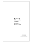
3.3 H.V. Control via Front Panel Signals
Fig. 3.1 Connecting the Main controllers
The Status output is capable of driving 50 ohm, the inputs are high impedance and each one is
provided with two bridge connectors for daisy chaining (ref. to FIG.3.1). Note that the high
impedance makes these inputs sensitive to noise, so the chain has to be terminated on 50 ohm
on the last module; the same is needed also if one module only is used, whose inputs have thus
to be properly matched. LEDs are provided for each input/output connector: they are ON when
the corresponding signal is "true".
The standard level (TTL or NIM) of the signals STATUS, KILL, VSEL, ISEL is selectable via the
Front panel switch "NIM/TTL".
20
30/07/2003
Soft. Ver. 1.41
3.3.1 STATUS (output)
It signals that an error condition has been detected in a channel. Via Software it is possible to
chose:
- the error conditions that cause the Alarm; (It is possible to set a Mask for each of these
three conditions Ovc,Ovv,Unv: if the mask is ON the corresponding error condition
causes the Alarm);
- the level of the output when there are no error conditions (Normal Level);
- the Alarm type (Pulsed or Level). If the option chosen is "Pulsed", The STATUS output
(when active) is a periodic signal (the period is about few hundred msec)
The STATUS signal is cleared (goes to the Normal level chosen) in these cases:
- If the error condition detected is an Overvoltage, the STATUS is cleared only when the
channel resumes its normal operating conditions.
- If the error condition detected is an Undervoltage, the STATUS is cleared only when the
channel resumes its normal operating conditions.
- If the error condition detected is an Overcurrent and the channel has not "Tripped", the
STATUS is cleared only when the channel resumes its normal operating conditions.
- If the channel has "Tripped" the STATUS is cleared in these ways
- by making a "Clear Alarm" procedure (see § 5.1);
- by turning the channel On.
3.3.2 KILL (input)
A pulse of at least 100 msec sent into this input will switch all the crate channels off regardless
of the Ramp-down or other parameters.
3.3.3 VSEL (input)
Two HV values can be programmed for each channel: V0set and V1set.They are selected by the
status of VSEL:
VSEL = False
VSEL = True
V0set selected
V1set selected
When channels are switched from V0 to V1 or viceversa, the HV drifts from one value to the
other at the rate programmed for each channel (Ramp-Up or Ramp-Down).
3.3.4 ISEL (input)
Two current limit values can be programmed for each channel: I0set and I1set. They are
selected by the status of ISEL:
ISEL = False
ISEL = True
I0set selected
I1set is selected
21
30/07/2003
Soft. Ver. 1.41
3.3.5 INTERLOCK (Input)
This input allows to switch off simultaneously all the SY 403 channels, thus operating like the
"KILL" input. The "Interlock" can be activated in two ways depending on the position of the two
position lever switch (HIGH/LOW) located near the INTERLOCK input .
If the switch is on position "LOW" the channels are switched off if the ground connection in the
"Interlock" input is removed.
Vice-versa if the switch is positioned on "HIGH" the channels are switched off if the "Interlock"
input is grounded.In order to turn the channels on again you must remove the Interlock
condition.
Any attempt to turn the channels on without removing the Interlock condition will result
unsuccessfully.
3.3.6 RESET (Input)
If a pulse of at least 30 µsec is applied to this input, the microprocessor is restarted and the
whole system resumes its operation from the beginning. All the high voltage outputs are dropped
to zero and put in the "OFF" state.
The system then reacts as it would react to a power on. If the system has been programmed for
an automatic recovery, it will restore the status of all the channels bringing all the high voltages
to their programmed values at the correct rate.
The same result is obtained by pushing the RESET push-button.
3.4 Manual Control
The manual interface houses a LCD display and 21 keys (0 - 9, ., ACK , left,right, up, down
and 5 Function keys). By using this interface it is possible to set all the parameters and to know
the status of all the channels in the crate. In particular permits the RS232 port configuration and
the H.S. CAENET address setting.
Some of the setting operation can be disabled via Terminal (see Disable keyboard command)
3.5 Remote Control
As previously described the remote control of the Model SY403 is possible via the RS232 port
and via H.S. CAENET link.
3.5.1 RS232 Port
Any VT100 compatible video terminal may be plugged into this standard RS232 C serial
Port.(see Fig 3.2 for the connector pin assignment). The setting of the Port has to be made in
accordance with the User terminal characteristics; the Baud rate and the communication
protocol parameters can be selected via Manual control. Detailed instructions are found in
chapter 4.4. A sophisticated Software runs on the MC68000 microprocessor housed in this
module; it acts as an user-friendly interface, to provide straightforward access
- to all the channels parameters of the crate directly connected to the terminal.
- to all the channels parameters of all the crates linked via the H.S.CAENET Network. In
this case the Crate connected directly to the terminal can be used as an H.S. CAENET
Controller (see below)
22
30/07/2003
Soft. Ver. 1.41
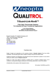
The minimum hookup includes pin 2,3 and 7
pin 7 Signal Ground
**
pin 6 Data Set Ready
) *
pin 3 (iTXD:Transmit
Data
pin 2 RXD: Receive Data
pin 1 Ground **
pin 20 Data Terminal Ready
( t)
* if this line is not connected, Mod. SY403
consider them high and will function normally
** In Mod. SY403 pin 1 e 7 are tied together
Fig 3.2 RS232 connector pin assignment
23
30/07/2003
Soft. Ver. 1.41
3.5.2 H.S. CAENET Operation
H.S. CAENET Network is a send and receive half duplex system; It permits asynchronous
serial transmission (1MBaud rate) of data packets along simple 50 Ohm coaxial cable. Several
devices (H.S. CAENET nodes) are able to share the same media to transmit and receive data.
Each node is able to receive the serial data packet and store it automatically in a FIFO (RX
FIFO) and transmit the data contained in another FIFO ( TX FIFO).Both FIFOs are 512 byte
deep.
Usually transfers between H.S. CAENET nodes take place according to the typical
Master/Slaves communication:
- There is a single Master : H.S. CAENET controller
- The Slaves are daisy chained on the network, and are identified by an address code
(from 0 to 99);
- the H.S. CAENET Master initiates the transmission, all the Slaves receive the data, and
only the Slave addressed then accesses the serial line to transmit the data requested by
the Master.
- The maximum data packet length is 512 bytes.
The address of the H.S. CAENET node of the SY403 (Crate #) is selectable via the Manual
interface, and its value ranges from 0 to 99. In this way up to 100 crates may be controlled from
a single point in two different ways:
- via a video terminal ( the crate directly connected to the terminal is the H.S. CAENET
Controller) In this case, the software available permits to operate to each SY403 in the H.
S. CAENET network as if they were directly connected to the terminal.
- or via one of the following CAEN H.S. CAENET Controllers:
A303 H.S. CAENET PC Controller,;
C117B H.S. CAENET CAMAC Controller;
V288 H.S. CAENET VME Controller.
Video terminal and the Controllers cannot be used simultaneously.
To avoid reflections it is necessary to terminate the H.S.CAENET line on a 50 Ω impedance.
This is accomplished in these ways:
- If the H.S.CAENET Controller is one of the crates :
by inserting a 50 Ω impedance terminator in one of the two LEMO 00 type connectors ( IN/OUT)
in the last and in the first crate of the chain.
- If the H.S.CAENET Controller is not one of the crates :
by inserting a 50 Ω impedance terminator in one of the two LEMO 00 type connectors ( IN/OUT)
of the last crate of the chain.
4. MANUAL OPERATION SOFTWARE VERSION 1.41
24
30/07/2003
Soft. Ver. 1.41
A single Crate can be operated manually through the 21 keys and the LCD display which are
located in the Front Panel. The relative software runs in the MC68000 microprocessor housed
in the Main Controller and provides the operator with a set of menus which allows him to solve
most of his problems quickly and easily. The meaning of the 5 Function keys located near the
bottom of the display is shown in the display itself. Some of the setting operation can be disabled
via Terminal (see Disable Keyboard command § 5.4.1)
The following table resumes all the possible keyboard operations:
Operation
program channels parameters
monitor channels parameters
configure the RS232 Port
set the H.S. CAENET address of
the Node
select the cause and the type of
the Alarm.
Keyboard enabled
Yes
don't care
don't care
Yes
Yes
The following figure shows the Menu structure of the software.
Fig. 4.1 Manual operation Menu Structure
4.1 Main Menu
At power on, the display starts displaying on the screen "C.A.E.N SY403"; then pressing any
key will appear the top-level Menu: the Main Menu. The version running in the Main Controller is
25
30/07/2003
Soft. Ver. 1.41
indicated on the top right of the display, near the software version is shown the actual H.S.
CAENET address of the SY403 (Crate #). The following figure shows the Main menu:The
submenu selections are shown in correspondence of the Function keys: (Note that display will
vary slightly from that shown with new software releases).
C.A.E.N.
SY403
Crate 02
V1.40
64 Channels High Voltage System
Main Menu
Display
Chann.
|
Modify
Chann.
|
Crate
Map
|
I/O
Config
|
|
Fig. 4.2 Main Menu
The operator selects the submenu by pressing the Function key corresponding to the option.
The Meaning of the options are:
Display Channel
Shows the status of the channel identified by its number (CH#).
Modify Channels
Modify the various channels parameters.
Crate Map
Display the status of the H.V. Channels Board inserted in the SY403 crate.
I/O Configuration
- Modify the RS232 Port configuration.
- Set the H.S. CAENET address (Crate #).
- Select the Alarm type.
The channels Parameters showed in the following are expressed in these units:
Vmon
Imon
HVmax
V0set
I0set
SVmax
Rup
Rdwn
Trip
Volt
µA
Volt
Volt
µA
Volt
Volt/sec
Volt/sec
Tenth of
second
26
30/07/2003
Soft. Ver. 1.41
4.2 Display Channel Option
This option is selected by pressing the Function key corresponding to the Main Menu Option
"Display Chann." It is actuated by two level Menu:
1th level:
Display Channel Status Menu.
It permits the channel number selection
2th level:
Status of Channel Menu.
It shows the Channel Status. In this submenu an option allows to enter directly in
the Modify Channel Menu without no need to return to Main Menu.
4.2.1 Display Channel Status Menu
The Display Channel Status Menu allows to choose the channel to be monitored by entering the
Channel number The Channel Name are also shown in this Menu.
C.A.E.N.
SY403
Crate 02
V1.40
Display channel status
Channel to be monitored [05]: _
Channel name : CHANNEL05
Display
|
|
|
|
Return
|
Fig. 4.3 Display Channel Status Menu.
COMMANDS
Channel to be monitored [#]:
use the numeric keypad to enter the number of the channel to be monitored.Its Channel Name is
automatically displayed.
Display
Go to next menu: Status of Channel Menu, where is shown the status of the channel entered; If
no channel number has been entered the following submenu will show the status of the channel
corresponding to the number in the brackets.
Return
Return to Main Menu.
Ack key
Same as Display.
27
30/07/2003
Soft. Ver. 1.41
4.2.2 Status of Channel Menu
This option is selected by pressing the Function key "Display "in the Display Channel Status
Menu.
The Status of Channel Menu allows to monitor five parameters (Vset, Iset, Vmon, Imon, Status)
of the channel previously selected. Vset and Iset are the High Voltage and Current limit
programmed values (V0/1sel, I0/1sel) actually selected by the external signals VSEL and ISEL.
The Channel Name are also shown in this Menu.
C.A.E.N.
SY403
Crate 02
Status of CHANNEL05
VSET: 1500.0
VREAD: 0012.1
Next
|
ISET:
IMON:
Previous
|
|
0000
0012
[05]
STATUS
Tripped
Modify
|
Fig. 4.4 Status of channel Menu.
COMMANDS
Next
Show the Status of the Next channel.
Previous
Show the Status of the Previous channel.
Modify
Go to the Modify Channel Menu:
Return
Return to Main Menu.
28
V1.40
Return
|
30/07/2003
Soft. Ver. 1.41
4.3 Modify Channels Option
This option is selected
- in Main Menu:
by pressing the Function key corresponding to the Option "Modify Chann.";
- in Status of Channels Menu:
by pressing the Function key corresponding to the Option "Modify ".
It is composed of a two level Menu:
1th level
Modify Channels Status Menu.
It is structured in four pages: each page shows different parameter of a group of four channels.
First Page
V0set, I0set, Status (1);
Second Page
V1set, I1set, Status (1);
Third Page
Vmax (Soft), Rup, Rdwn;
Fourth Page
Trip,Pon,Pdwn:
(1): Status On/Off of the channel : it is the H.V. On/Off of the channel (see § 3.2.14)
In each page the Channel Name and the Channel # of the channels under control are also
shown. The highlight bar indicates the Current Parameter. If the Keyboard is enabled, the
Current Parameter is affected by the Modify command (Change/Edit).
Use the Arrow keys to move the highlight bar to the parameter which has to be modified; the Up
and Down arrow keys permit to scroll the channels on the display, showing another group of four
channel. It is possible to modify all the parameters displayed except the Channel Name.
2th level
It is active only if the Keyboard is enabled.It is composed of three different menus:
- Edit Parameters Menu
In this menu it is possible to edit the parameter value and to modify it by using the numeric
keypad.
- Change Parameters Menu
In this menu it is possible to enter a new parameter value by using the numeric keypad.
- Change CH# Menu
This menu permits to select another group of channels by entering the number of one of the
channels of that group.
29
30/07/2003
Soft. Ver. 1.41
4.3.1 Modify Channels Status Menu
The following figures show the three Pages of the menu, press the More key to switch between
the pages.
CHANNEL
V0SET
I0SET
STATUS
CHANNEL28
CHANNEL29
CHANNEL30
CHANNEL31
0000.0
0000.0
0000.0
0000.0
0000
0000
0000
0000
Off
Off
Off
Off
More
|
Edit
|
CH#
28
29
30
31
Change Display Return
|
|
|
Fig. 4.5 Modify Channel Status Menu: First page
CHANNEL
V1SET
I1SET
STATUS
CHANNEL28
CHANNEL29
CHANNEL30
CHANNEL31
0000.0
0000.0
0000.0
0000.0
0000
0000
0000
0000
Off
Off
Off
Off
More
|
Edit
|
CH#
28
29
30
31
Change Display Return
|
|
|
Fig. 4.6 Modify Channel Status Menu: Second page
CHANNEL
VMAX
CHANNEL28
CHANNEL29
CHANNEL30
CHANNEL31
More
|
3000
3000
3000
3000
Edit
|
RUP
RDWN
CH#
100
100
100
100
100
100
100
100
28
29
30
31
Change Display Return
|
|
|
Fig. 4.7 Modify Channel Status Menu: Third page
CHANNEL
TRIP
CHANNEL28
CHANNEL29
CHANNEL30
CHANNEL31
More
|
Edit
|
inf.
inf.
inf.
inf.
PON
PDWN
CH#
Off
Off
Off
Off
Kill
Kill
Kill
Kill
28
29
30
31
Change Display Return
|
|
|
Fig. 4.8 Modify Channel Status Menu: Fourth page
30
30/07/2003
Soft. Ver. 1.41
COMMANDS
If the Keyboard is disabled Change and Edit are not available.
If the Keyboard is enabled More, Display, Return, Change are always active, while Edit is
active only when the Current Parameter is one of the following: V0set, I0set, V1set, I1set,Vmax,
Rup, Rdwn, Trip.
More
Switch between the pages.
Edit (This Command is available if the Keyboard is enabled)
Go to the Edit Parameter Menu.The value of the Current Parameter can be edited and modified;
This command is active when the Current Parameter can have different values (V0set , I0set,
V1set, I1set,Vmax, Rup, Rdwn, Trip), it is not active when the Current Parameter shares only
two values (Status, Pon, Pdwn); for these parameters only the Change command is used.
Change (This Command is available if the Keyboard is enabled)
Change the value of the current parameter.
Pressing the Change key the value of the Current Parameter is changed:
- if the Current Parameter can take only two different values (Status, Pon, Pdwn) by
pressing the Change key it toggles between the two values, for example if the Current
Parameter is Status (Status On/Off of the channel) and its value is Off, pressing "Change"
the value becomes On and vice versa;
- If the Current Parameter can take different values (V0set, I0set, V1set, I1set,Vmax, Rup,
Rdwn, Trip) the display will show the Change Parameter Menu (The same result is
achieved by pressing one of the numeric keys).
- if the Current Parameter is the CH # the display will show the Change CH # Menu.
Display
Return to the Display Menu.
Return
Return to Main Menu.
Up and Down arrow keys
Permits to scroll the channels on the display, showing another group of four channels.
Numeric keys
- If the Current Parameter can take different values (V0set, I0set, V1set, I1set,Vmax, Rup,
Rdwn, Trip), by pressing the numeric key corresponding to the most significant figure of the new
Parameter value, the display will show the Change Parameter Menu (the corresponding number
is displayed as the most significant figure of the value).
31
30/07/2003
Soft. Ver. 1.41
4.3.2 Edit Parameter value Menu
This Menu is active if the Keyboard is enabled; it is selected by pressing the "Edit"Function key
in the Modify Channel Status Menu.
The Edit Parameter Menu allows to edit and modify the Current Parameter. By pressing the
"Edit" key the highlight bar disappeared, and a blinking cursor appears under the first character
of the value. The cursor indicates the Current Figure of the parameter; use the left and right
arrow keys to move the cursor along the figures.
On writing a new value and pressing the Ack key or "Return" the Current Parameter will take this
new value; if the Ack key is entered without having giving any change the parameter value
remains the old one.
By using the Up and Down arrow keys it is possible to increment/decrement the Current Figure
- pressing the Up arrow key the Current Figure of the Parameter value of all the
channels is incremented by the minimum step possible
- pressing the Down arrow key the Current Figure of the Parameter value of all
the channels is decremented by one by the minimum step possible
CHANNEL
V0SET
I0SET
STATUS
CHANNEL28
CHANNEL29
CHANNEL30
CHANNEL31
1500.0
0000.0
0000.0
0000.0
0000
0000
0000
0000
Off
Off
Off
Off
|
|
|
|
CH#
28
29
30
31
Return
|
Fig. 4.9 Edit Parameter Menu.
COMMANDS
Up and Down Arrow keys
Increment/decrement by the minimum step possible the Current Figure of the Current
Parameter. The cursor indicates the Current Figures.
Return
The Current Parameter will take the value; and the display returns to the previous menu.If the
Return key is pressed without having giving any change the parameter value remains the old
one.
Ack key
The Current Parameter will take the value; and the display returns to the previous menu.If the
Ack key is pressed without having giving any change the parameter value remains the old one.
32
30/07/2003
Soft. Ver. 1.41
4.3.3 Change Parameter value Menu
If the Keyboard is enabled this option is available in the Modify Channel Status Menu when the
Current Parameter can assume several values (V0set, I 0set, V1set, I1set, Vmax, Rup, Rdwn,
Trip). It is selected in two ways:
- by pressing the "Change" Function key;
- by pressing the numeric key corresponding to the most significant figure of the new
Parameter value;
The Change Parameter value Menu allows to enter the new parameter value.
By pressing the Change key the highlight bar disappeared, the actual parameter value is cleared
and a blinking cursor appears under the most significant figure of the value.
If a numeric key has been pressed, the corresponding number is displayed as the most
significant figure of the value.
CHANNEL
V0SET
I0SET
STATUS
CHANNEL28
CHANNEL29
CHANNEL30
CHANNEL31
0000.0
_
0000.0
0000.0
0000
0000
0000
0000
Off
Off
Off
Off
|
|
|
|
CH#
28
29
30
31
Abort
|
Fig. 4.10 Change Parameter value Menu.
COMMANDS
Abort
The operation is aborted: the parameter value remains the old one, the display returns to the
previous menu.
Ack key
The Current Parameter will take the value; and the display returns to the previous menu. If the
Ack key is pressed without having giving any change the parameter value remains the old one.
33
30/07/2003
Soft. Ver. 1.41
4.3.4 Change Channel Number Menu
This Menu is active if the Keyboard is enabled.
It is available in the Modify Channel Status Menu. when the Current Parameter is the Channel
Number CH#; It is selected in two ways:
- by pressing the "Change"Function key
- by pressing the numeric key corresponding to the most significant figure of the new
Channel Number.
The Change Channel Number Menu allows to select another group of four channels by entering
the number of one of the channels of this group.
By pressing the Change key the highlight bar disappeared, the actual Channel Number is
cleared and a blinking cursor appears under the first character of the value. If a numeric key has
been pressed, the corresponding number is displayed as the most significant figure of the
Channel number.Use the numeric keypad to enter the new CH# . If the channel entered is not
present in the crate an error message is displayed.
CHANNEL
V0SET
I0SET
STATUS
CHANNEL28
CHANNEL29
CHANNEL30
CHANNEL31
0000.0
0000.0
0000.0
0000.0
0000
0000
0000
0000
Off
Off
Off
Off
|
|
|
|
CH#
28
29
_
31
Exec
|
Fig. 4.11 Change Channel Number Menu.
COMMANDS
Exec
The display returns to the previous menu showing the new group of four channels that contains
the CH# entered. if the Exec key is pressed without having giving any change the group
displayed remains the old one.
Ack key
The display returns to the previous menu showing the new group of four channels that contains
the CH# entered. if the Ack key is pressed without having giving any change the group
displayed remains the old one.
34
30/07/2003
Soft. Ver. 1.41
4.4 Crate Map Option
This option is selected by pressing the Function key corresponding to the Main Menu Option
"Crate Map.".This option is used to display the crate configuration (see Fig. 4.12). On the display
a screen named "Crate Map" will appear. In four lines are reported the kind of HV Boards
inserted in the four slots of the crate .
The following Board characteristics are displayed:
- The Max Output voltage;
- The Max Current;
- The Polarity;
- the Vmax hardware.
If a slot is empty, the message " Board not present" will be displayed.
C.A.E.N.
Mod.
Mod.
Mod.
Mod.
|
SY403
Crate 02
Crate Map
A503
A503
A503
A503
3.0
3.0
3.0
3.0
|
KV
KV
KV
KV
3000
3000
3000
3000
|
µA
µA
µA
µA
|
Fig. 4.12 Crate Map Menu
COMMANDS
Return
Return to Main Menu.
35
V1.40
HVmax
Neg.
3095
Neg.
3095
Neg.
3095
Neg.
3095
Return
|
30/07/2003
Soft. Ver. 1.41
4.5 I/O Configuration Option
This option is selected by pressing the Function key corresponding to the Main Menu Option
"I/O Config.". The display shows the I/O Configuration Menu that allows to modify the RS232
Configuration or the CAENET configuration.
C.A.E.N.
SY403
64 Channels
RS 232
Config.
|
CAENET
Config
|
Crate 02
V1.40
High Voltage System
Status
Alarm
|
|
Return
|
Fig. 4.13 I/O Configuration Menu
COMMANDS
RS232 Configuration
Go to the RS232 Configuration Menu that permits to modify the RS232 Port configuration.
CAENET Configuration
Go to the CAENET Configuration Menu where it is possible to set the H.S. CAENET address
(Crate#).
Status Alarm (STATUS output signal configuration)
Go to the Status Alarm Configuration Menu where it is possible to set the error condition that
cause the Alarm and the "STATUS" signal characteristic
Return
Return to Main Menu.
36
30/07/2003
Soft. Ver. 1.41
4.5.1 RS232 Configuration Option
This option is selected by pressing the Function key corresponding to the I/O Configuration
Option "RS232 Config." It is actuated by two level Menu:
1th level: RS232 Configuration Menu.
It shows the value of the RS232 parameters.
2th level: at this level belong four submenus :
- Baud Rate Selection composed of 4 pages
- Parity Selection
- Character length Selection
-Stop bits number Selection
4.5.1.1. RS232 Configuration Menu
The RS232 Configuration Menu shows the value of the RS232 parameters.
C.A.E.N.
SY403
Crate 02
V1.40
RS232 configuration
Baud rate = 9600
8 bits/character
Baud
|
Parity
|
Bits #
|
no Parity
1 Stop bit
Stop #
|
Return
|
Fig. 4.14 RS232 Configuration Menu
COMMANDS
Baud
set the RS232 Baud rate; go to submenu: Baud Rate Selection Menu.
Parity
set the RS232 Parity; go to submenu: Parity Selection Menu.
Bits #
set the RS232 Character length; go to submenu: Character length Selection.Menu.
Stop #
set the RS232 Stop bits number; go to submenu: Stop bits number Selection.Menu.
Return
Return to I/O Configuration Menu.
37
30/07/2003
Soft. Ver. 1.41
4.5.1.2. RS232 Baud Rate Selection Menu
The following figures show the structure of the four pages of the menu, press the More key to
switch between the pages.
C.A.E.N.
SY403
Crate 02
V1.40
RS232 configuration
Actual Baud rate is
9600
Select new value
n0
|
n1
|
n2
|
n3
|
More
|
Fig. 4.15 Structure of the Baud Rate Selection Menu (four pages)
COMMANDS
no..n3
By pressing the appropriate Function key the Baud rate is modified and the display returns to the
previous menu.
The following table shows the different values of n0..n3 in the four pages:
Page
1
2
3
4
n0
n1
n2
n3
4800
50
150
1800
7200
75
300
2000
9600
110
600
2400
19200
134.5
1200
3600
More
Switch between the pages.
38
30/07/2003
Soft. Ver. 1.41
4.5.1.3. RS232 Parity Selection Menu
This menu permits to set the RS232 Parity value.
C.A.E.N.
SY403
Crate 02
V1.40
RS232 configuration
Actual Parity is odd
Select new value
none
|
odd
|
even
|
|
|
Fig. 4.16 Parity Selection Menu.
COMMANDS
none,odd,even
By pressing the appropriate Function key the corresponding Parity value is set and the display
returns to the previous menu.
39
30/07/2003
Soft. Ver. 1.41
4.5.1.4. RS232 Character Length Selection Menu
This menu allows to set the RS232 Character length.
C.A.E.N.
SY403
Crate 02
V1.40
RS232 configuration
Actual Character Length is 8 bits
Select new value
7
|
8
|
|
|
|
Fig. 4.17 Character Length Selection Menu
COMMANDS
7,8
By pressing the appropriate Function key the RS232 character length is set to the
corresponding value and the display returns to the Previous menu.
40
30/07/2003
Soft. Ver. 1.41
4.5.1.5. RS232 Stop Bits Number Selection Menu
This menu permits to set the RS232 number of Stop bits value
C.A.E.N.
SY403
Crate 02
V1.40
RS232 configuration
Actual # of stop bits is 1
Select new value
1
|
1.5
|
2
|
|
|
Fig. 4.18 Stop Bits Number Selection Menu
COMMANDS
1,1.5,2
By pressing the appropriate Function key the stop bits number is set to the corresponding value
and the display returns to the previous menu.
41
30/07/2003
Soft. Ver. 1.41
4.5.2 CAENET Configuration Option
This option are selected by pressing the Function key corresponding to the I/O Configuration
Option "CAENET Config." It shows the H.S. CAENETY address of the SY403 (Crate #).
If the keyboard is enabled It allows to set the address of H.S. CAENET node housed in the
Module(Crate #), the address can range from 0 to 99.
C.A.E.N.
SY403
Crate 02
V1.40
CAENET configuration
Actual Crate # is 2
Enter new value : _
|
|
|
|
Return
|
Fig. 4.19 CAENET Configuration Menu
COMMANDS
Enter new value: (This option is available if the Keyboard is enabled)
Use the numeric keypad to enter the new value of the H.S.CAENET address (Crate #).
Return
Return to I/O Configuration Menu.
Ack key
The H.S.CAENET address (Crate #) will take the value entered; and the display returns to the
Main Menu. if the Ack key is pressed without having giving any change the Crate # value
remains the old one.
42
30/07/2003
Soft. Ver. 1.41
4.5.3 Status Alarm Configuration option
This option are selected by pressing the Function key corresponding to the I/O Configuration
Option "Status Alarm." It allows to chose the error conditions which cause an Alarm, and the
Alarm signal (STATUS signal) characteristics.
Five options can be selected;
- the Normal Level of the Alarm signal STATUS (High/Low);
This is the STATUS level when the signal is not active;
- the type of the Alarm signal (Level/Pulsed); If the option chosen is "Pulsed" The STATUS
output (when active) is a periodic signal (the period is about few hundred msec);
- a Mask (On/Off) for each of these three error conditions Ovc,Ovv,Unv: if the mask is ON
the corresponding error condition on at least one channel sets the Alarm.
The highlight bar indicates the Current Parameter. If the Keyboard is enabled, the Current
Parameter is affected by the Change command.
Use the Arrow keys to move the highlight bar to the parameter which has to be modified; The
change command causes the parameter to toggle between its two values; for example if the
Alarm Type value is "Pulsed", pressing the Change Key the value becomes "Level" and
viceversa.
Status Alarm configuration
Normal Level:
Alarm Type :
OVC Alarm
:
OVV Alarm
:
UNV Alarm
:
Change
|
|
|
Low
Level
On
Off
Off
|
Return
|
Fig. 4.20 Status Alarm Configuration Menu
COMMANDS
Change: (This option is available if the Keyboard is enabled)
By pressing the Change key the Current Parameter toggles between the two values that can
assume.
Return
Return to I/O Configuration Menu.
43
30/07/2003
Soft. Ver. 1.41
5. TERMINAL OPERATION SOFTWARE VERSION 1.41
A multicrate system can be controlled by a VT100 compatible terminal plugged into the RS232
port located on the Front Panel as described in § 3.5.
The relative software runs on an MC68000 microprocessor housed in the Main Controller and
provides the operator with a set of menus which allows him to solve most of his problems quickly
and easily.
It allows to control all the Crate on the same H.S. CAENET network and for each Crate it is
possible
- to program and monitor all the channel parameters described in the chapter 3;
- to arrange the Crate channels in different Groups, and to program common parameter
values for all the channels belonging to the Group, with a single operation. It is possible to
have up to 16 Groups. To the first Group (GROUP00) belong all the channels of the
Crate;
- to "kill" all the channels of the Crate;
- to reset the Status output signal;
- to set for each channel a Password protection to avoid an improper channel parameters
setting;
- to restore the default Factory configuration of all the channels parameters;
- To select the cause and the type of the Alarm;
5.1 Main Menu
At power on, appears on the screen "C.A.E.N SY403"; then pressing any key will appear the
top level menu, the "Main Menu" and the operator can then select the next action. The software
version is indicated on the top right of the screen. (Note that screens will vary slightly from that
shown in the following with new software releases).
A submenu selection can then be made by pressing the key correspondent to the first letter of
the option (highlighted letter).
44
30/07/2003
Soft. Ver. 1.41
C.A.E.N.
M A I N
SY403
V1.40
Crate 01
M E N U
Display
Protections
Crate
Map
Kill
Alarms
Status
Format
Quit
Display/Modify channels
Set/Reset password
Connect a new crate
Crate Map
Kill all channels
Reset alarms
Select type of alarm
Reformat EEPROM
Abandon program
Select item
Fig 5.1 Main Menu
OPTIONS
D Display Display/Modify channels
Shows the status of one or more channels Grouped according to symbolic names. Allows
viewing and eventually modifies the parameter of a single channel or a Group of channels
having a common symbolic name.
P Protections Set/Reset password
Protects the system from misuse and allows to disable the Keyboard .
C Crate Connect a new Crate
It allows to select which SY403 on the H.S. CAENET network has to be controlled via H.S.
CAENET.
M Map Crate Map
It allows to display the Crate configuration.
K Kill Kill all channels
All H.V. channels of the Crate are switched off.
A Alarms Reset alarms
Resets the STATUS output signal.
S Status Select type of Alarm
It allows to chose the error conditions which cause an Alarm, and the Alarm signal (STATUS
signal) characteristics. The Status command is available only when the Password is disabled; if
the Password is enabled this command is not shown
F Format Reformat EEPROM
This command restores in the permanent memory (EEPROM) the default factory configuration
of the channels parameter. The Format command is available only when the Password is
disabled; if the Password is enabled this command is not shown (Format sets the Password to
the default factory Password).
45
30/07/2003
Soft. Ver. 1.41
5.2 Display/Modify Channels Option
This option is selected on entering the letter "D" in the Main Menu.The screen will show the
parameters values of the channels of the last Group displayed. If this option is selected on a
Model just shipped from the factory or after a Format command the screen will show the status
of the GROUP00 that contains all the channels present in the Crate. The default factory
configuration of the system is the following:
- the symbolic name of the Groups are GROUP00 .. GROUP15;
- to the GROUP00 belongs all the channels (the GROUP00 configuration is fixed);
- no channels belong to the other Groups.
Each screen contains 16 channels, the remaining channels will be shown on the other pages by
typing the letter "P".(Page command). By entering the letter "M" (More command) the screen will
show the other parameters of the same channels.
On the top of the screen are also shown the following parameters:
- the status On/Off of the "H.V. EN" switch;
- which High Voltage and Current limit programmed value (V0/1sel, I0/1sel) are actually
selected by the external signals VSEL and ISEL.
- the H.S. CAENET address of the crate connected (Crate XX where XX is the Crate #);
In the first screen for each channel are shown the following parameters:
Channel, Vmon, Imon, HVmax, V0set (V1set), I0set (I1set), Hv, Status, CH#
Channel is the Channel Name.
HVmax is the Vmax Hardware.
Hv is the status "On"/"Off" of the channel; by setting this parameter On, the channel is switched
On.
By pressing the letter "V"(V/Isel command) on the screen are displayed the other two set values
for the current and voltage, for example, if V0set and I0set are displayed, pressing "V" the
screen will show V1set and I1set and viceversa.
In the second screen for each channel are shown the following parameters:
Channel, SVmax, Rup, Rdwn, Trip, Pon, Pdwn, Password, On/Off, CH#
SVmax is the Vmax Software; if the SVmax value programmed is less then the actual Vset
value, the Vset take this value.
46
30/07/2003
Soft. Ver. 1.41
Password is the status of the protection :
- If the Password is enabled:
- if The Channel Password parameter = "Required" it is not possible to modify the
channels parameter;
- if The Channel Password parameter is blank it is possible to modify all the
channels parameters except the password and the On/Off parameter.
- If the Password is disabled it is possible to modify every value of the channel parameters
regardless of its Password Parameter.
On/Off is the status of the Power-on enable:
- if ="Enabled" the channel react at power on following the status of the Pon parameter;
- if there is a blank field at the power on the channel is Off regardless the status of the Pon
parameter.
in the following pages are shown the structure of the two screens for the GROUP00 and for a
generic Group TEST1 that contains 3 channels.The SY403 connected is in the following
conditions:
- the H.V. Enable is On;
- V0sel and I0sel are actually selected by the external signals VSEL and ISEL;
- the SY403 Crate number is 01.
On the bottom of the screen are shown some of the Commands available; the operator selects
the command by typing the key correspondent to the first letter of the Command itself
(highlighted letter). The highlight bar indicates the Current Parameter and the Current
Channel:
- The Current Parameter is affected by the Modify command shown on the bottom of the
screen (Change/Edit), (In particular it is possible to Modify the Channel Name).
- The Current Channel is affected by the Modify Group configuration command shown on
the bottom of the screen (Add,Insert,Replace,Delete).These commands are not available
for the GROUP00, because its configuration is fixed.
Use the Arrow keys to move the highlight bar to the parameter which has to be modified.
- The 4 commands Add, Insert, Replace and Delete allow to modify the Group
configuration adding or removing channels; they are not available for the GROUP00
because its configuration is fixed. If the Group displayed does not have any channel, only
the commands Add and Insert are present.
- The Edit command is available when the Current Parameter can take different values
(Channel, V0/1set , I0/1set,SVmax , Rup, Rdwn, Trip).
- The Page command is shown when there are more than 16 channels in the Group.
- The Switch command allows to switch between this screen and the Group operation
screen.
47
30/07/2003
Soft. Ver. 1.41
The Parameters showed on the screen are expressed in the following units:
Vmon
Imon
HVmax
V0set
I0set
SVmax
Rup
Rdwn
Trip
Volt
µA
Volt
Volt
µA
Volt
Volt/sec
Volt/sec
Tenth of
second
48
30/07/2003
Soft. Ver. 1.41
GROUP00
C.A.E.N.
Hv_En is: On
Channel
CHANNEL00
CHANNEL01
CHANNEL02
CHANNEL03
CHANNEL04
CHANNEL05
CHANNEL06
CHANNEL07
CHANNEL08
CHANNEL09
CHANNEL10
CHANNEL11
CHANNEL12
CHANNEL13
CHANNEL14
CHANNEL15
Vmon
0000.00
0499.88
0500.04
0499.84
0000.00
0000.00
0000.00
0000.00
0000.00
0000.00
0100.52
0000.00
0000.00
0000.00
0000.00
0000.00
SY403
V0-SEL
Imon
0000.00
0000.00
0000.00
0000.00
0000.00
0000.00
0000.00
0000.00
0000.00
0000.00
0000.01
0000.00
0000.00
0000.00
0000.00
0000.00
HVmax
0675
0675
0675
0675
0675
0675
0675
0675
0675
0675
0675
0675
0675
0675
0675
0675
V1.41
I0-SEL
V0set
0500.60
0500.64
0500.68
0500.56
0500.56
0500.56
0500.56
0400.56
0500.56
0500.56
0100.56
0500.56
0500.56
0500.56
0500.56
0500.56
Crate 01
I0set
0100.41
0100.41
0100.41
0100.41
0100.41
0100.41
0100.41
0100.41
0050.20
0050.20
0050.20
0050.20
0050.20
0050.20
0050.20
0050.20
Hv
Off
On
On
On
Off
Off
Off
Off
Off
Off
On
Off
Off
Off
Off
Off
Page 0
Status
Ch#
00
01
02
03
04
05
06
07
08
09
10
11
12
13
14
15
Quit Edit Change Update Page More Switch V/Isel
Fig. 5.2 GROUP00 screen 1 of page 0 (Current Par. = Channel, V0set, I0set)
GROUP00
Channel
CHANNEL00
CHANNEL01
CHANNEL02
CHANNEL03
CHANNEL04
CHANNEL05
CHANNEL06
CHANNEL07
CHANNEL08
CHANNEL09
CHANNEL10
CHANNEL11
CHANNEL12
CHANNEL13
CHANNEL14
CHANNEL15
C.A.E.N.
Hv_En is: On
SVmax
0600
0600
0600
0600
0600
0600
0600
0600
0600
0600
0600
0600
0600
0600
0600
0600
Rup
020
020
020
020
020
020
020
020
020
020
020
020
020
020
020
020
Rdwn
020
020
020
020
020
020
020
020
020
020
020
020
020
020
020
020
SY403
V0-SEL
Trip
010.0
010.0
010.0
010.0
010.0
010.0
010.0
010.0
010.0
010.0
010.0
010.0
010.0
010.0
010.0
010.0
V1.41
I0-SEL
Pon
Off
Off
Off
Off
Off
Off
Off
Off
Off
Off
Off
Off
Off
Off
Off
Off
Pdwn
Kill
Kill
Kill
Kill
Kill
Kill
Kill
Kill
Kill
Kill
Kill
Kill
Kill
Kill
Kill
Kill
Crate 01
Password
Required
Required
Required
Required
Required
Required
Required
Required
Required
Required
Required
Required
Required
Required
Required
Required
On/Off
Enabled
Enabled
Enabled
Enabled
Enabled
Enabled
Enabled
Enabled
Enabled
Enabled
Enabled
Enabled
Enabled
Enabled
Enabled
Enabled
Quit Edit Change Update Page More Switch
Fig 5.3 GROUP00 screen 2 of page 0 (Current Par. = Channel, SVmax, Rup, Rdwn, Trip)
49
Page 0
Ch#
00
01
02
03
04
05
06
07
08
09
10
11
12
13
14
15
30/07/2003
Soft. Ver. 1.41
TEST1
C.A.E.N.
Hv_En is: On
Channel
CHANNEL01
CHANNEL04
CHANNEL41
Vmon
0499.88
0000.00
2000.20
Imon
0000.00
0000.00
0000.00
SY403
V0-SEL
HVmax
0675
0675
3125
V1.41
I0-SEL
V0set
0500.64
0500.56
2000.20
Crate 01
I0set
0100.41
0100.41
1185.00
Hv
On
Off
On
Page 0
Status
Ch#
01
04
41
Quit Edit Change Add Insert Replace Delete Update More Switch V/Isel
Fig. 5.4 Group TEST1: screen 1 of page 0 (Current Parameter = Channel, V0set, I0set)
TEST1
Channel
CHANNEL01
CHANNEL04
CHANNEL41
C.A.E.N.
Hv_En is: On
SVmax
0600
0600
3000
Rup
020
020
100
SY403
V0-SEL
Rdwn Trip
020 010.0
020 010.0
100 010.0
V1.41
I0-SEL
Pon
Off
Off
Off
Pdwn
Kill
Kill
Kill
Crate 01
Password
Required
Required
Required
On/Off
Enabled
Enabled
Enabled
Quit Edit Change Add Insert Replace Delete Update More Switch
Fig 5.5 Group TEST1: screen 2 of page 0
(Current Parameter = Channel, SVmax, Rup, Rdwn, Trip)
50
Page 0
Ch#
01
04
41
30/07/2003
Soft. Ver. 1.41
COMMANDS
Q Quit
Return to Main Menu.
E Edit
Go to the Edit Parameter Screen.The value of the Current Parameter can be edited and
modified. This command is active when the Current Parameter can have different values
(Channel, V0set, I0set, V1set, V0set, SVmax, Rup, Rdwn, Trip), it is not active when the Current
Parameter can assume only two values (Hv, Pon, Pdwn, Password, On/Off); for these
parameters only the Change command is available.
C Change
Change the value of the current parameter.
Entering the "C" key the value of the Current Parameter is changed:
- if the Current Parameter can take only two different values (Hv, Pon, Pdwn, Password,
On/Off) it toggles between this two values, for example if the Current Parameter is Hv
and its value is Off, entering "C" the value becomes On and vice versa;
- If the Current Parameter can take different values (Channel, V0set, I0set, V1set, I1set,
SVmax, Rup, Rdwn, Trip) the display will show the Change Parameter Screen where
the previous value are cleared and a new one has to be typed (the same result is
achieved by pressing one of the numeric key).
A Add channel (Command not available for the GROUP00)
Go to the Add Channel Screen. Add a channel to the Group.
I Insert channel (Command not available for the GROUP00)
Go to the Insert Channel Screen. Insert a new channel under the Current Channel in the
Group.
R Replace channel (Command not available for the GROUP00)
Go to the Replace Channel Screen. Replace the Current Channel with a channel which will be
selected in the Replace Channel screen.
D Delete channel (Command not available for the GROUP00)
Remove the Current Channel to the Group.
U Update
Refresh Screen.
P Page
Show the next Status page with other 16 channels of the Group, the Page command is
available when there are more than 16 channels in the Group.
51
30/07/2003
Soft. Ver. 1.41
M More
Show the next screen of the same page.
The parameters shown in the two screens are the following:
screen 1: Channel, Vmon, Imon, HVmax, V0set (V1set), I0set (I1set), Hv, Status;
screen 2 : Channel, SVmax, Rup, Rdwn, Trip, Pon, Pdwn, Password, On/Off.
S Switch screen
Go to the Group Operation Screen where it is possible:
- to modify the parameters of the entire Group displayed;
- to show the Status of another Group.
To return to the previous screen it is sufficient to enter another time the "S" key.
V Vsel Isel 0/1 selection
Show the other two set values for the current and voltage, for example, if V0set and I0set are
displayed, by pressing "V" the screen will show V1set and I1set and viceversa.
1,0 Set a two values parameter
If the Current Parameter can assume only two values (Hv, Pon, Pdwn, Password, On/Off), it is
possible to use the keys "1" and "0" to set the two different values (instead of use the "C" key
Change Command). The following table shows the usage of the keys:
Key
Hv
Pon
Pdwn
Password
On/Off
"0"
"1"
Off
On
Off
On
Kill
Rdwn
...
Required
...
Enabled
Numeric keys
- If the Current Parameter can take different values (V0set, I0set, V1set, I1set,Vmax, Rup,
Rdwn, Trip) by entering the number corresponding to the most significant figure of the new
Parameter value, the display will show the Change Parameter Screen. The corresponding
number is displayed as the most significant figure of the value.
52
30/07/2003
Soft. Ver. 1.41
5.2.1 Edit Parameter Screen
This option is selected on entering the letter "E" in the Status Display Screen. In this Screen it is
possible to modify the value of the Current Parameter previously selected.
By pressing the "Edit" key the highlight bar disappears, and a blinking cursor appears under the
first character of the value (No command is available on the bottom of the screen). The cursor
indicates the Current Figure of the parameter; use the left and right arrow keys to move the
cursor along the figures.
On writing a new value and pressing "return " the Current Parameter will take this new value; if a
"return "is entered without having giving any change the parameter value remains the old one.
If the Current Parameter is different from the Channel Name, by using the Up and Down arrow
keys it is possible to increment/decrement the Current Figure
- pressing the Up arrow key the Current Figure of the Parameter value of all the
channels is incremented by the minimum step possible
- pressing the Down arrow key the Current Figure of the Parameter value of all
the channels is decremented by one by the minimum step possible
COMMANDS
Up and Down Arrow keys
Increment/decrement by the minimum step possible the Current Figure of the Current
Parameter. The cursor indicates the Current Figures.
Ctrl - Z
Clear any modification and restore the old parameter value.
Refer to this paragraph for the usage of the various Edit screens named in the following of the chapter:
- Edit Channel Screen
- Edit Group Name Screen
53
30/07/2003
GROUP00
Channel
CHANNEL00
CHANNEL01
CHANNEL02
CHANNEL03
CHANNEL04
CHANNEL05
CHANNEL06
CHANNEL07
CHANNEL08
CHANNEL09
CHANNEL10
CHANNEL11
CHANNEL12
CHANNEL13
CHANNEL14
CHANNEL15
Soft. Ver. 1.41
C.A.E.N.
Hv_En is: On
SVmax
3000
2500
3000
3000
3000
3000
3000
3000
3000
3000
3000
3000
3000
0444
3000
3000
Rup
100
100
100
100
100
100
100
100
100
100
100
100
100
444
100
100
SY403
V0-SEL
Rdwn
100
100
100
100
100
100
100
100
100
100
100
100
100
100
100
100
Trip
010.0
010.0
010.0
010.0
010.0
010.0
010.0
010.0
010.0
010.0
010.0
010.0
010.0
010.0
010.0
010.0
V1.40
I0-SEL
Pon
Off
Off
Off
Off
Off
Off
Off
Off
Off
Off
Off
Off
Off
On
Off
Off
Pdwn
Kill
Kill
Kill
Kill
Kill
Kill
Kill
Kill
Kill
Kill
Kill
Kill
Kill
Kill
Kill
Kill
Crate 01
Password
Required
Required
Required
Required
Required
Required
Required
Required
Required
Required
Required
Required
Required
Required
Required
Required
Fig. 5.6 Edit Parameter Screen
(the SVmax of CHANNEL 01 is edited)
54
On/Off
Enabled
Enabled
Enabled
Enabled
Enabled
Enabled
Enabled
Enabled
Enabled
Enabled
Enabled
Enabled
Enabled
Enabled
Enabled
Enabled
Page 0
Ch#
00
01
02
03
04
05
06
07
08
09
10
11
12
13
14
15
30/07/2003
Soft. Ver. 1.41
5.2.2 Change Parameter Screen
This option is available in the Status Display Screen when the Current Parameter can assume
several values (Channel, V0set, I0set, V1set, I1set, SVmax, Rup, Rdwn, Trip); It is selected in
two ways:
- by pressing the "C" key ;
- by entering the number corresponding to the most significant figure of the new value;
In this screen it is possible to enter the new parameter value: Entering the "C" key the previous
value of the Current Parameter is cleared and a new one has to be typed. The highlight bar
disappeared, the actual parameter value is cleared and a blinking cursor appears under the first
character of the value. If a number has been entered (instead of the letter "C") the number is
displayed as the most significant figure of the value No command is available on the bottom of
the screen.
On writing a new value and pressing "return " the Current Parameter will take this new value; if a
return is entered without having giving any new value, the parameter will maintain the old one
GROUP00
Channel
CHANNEL00
CHANNEL01
CHANNEL02
CHANNEL03
CHANNEL04
CHANNEL05
CHANNEL06
CHANNEL07
CHANNEL08
CHANNEL09
CHANNEL10
CHANNEL11
CHANNEL12
CHANNEL13
CHANNEL14
CHANNEL15
C.A.E.N.
Hv_En is: On
SVmax
3000
25
3000
3000
3000
3000
3000
3000
3000
3000
3000
3000
3000
0444
3000
3000
Rup
100
100
100
100
100
100
100
100
100
100
100
100
100
444
100
100
SY403
V0-SEL
Rdwn
100
100
100
100
100
100
100
100
100
100
100
100
100
100
100
100
Trip
010.0
010.0
010.0
010.0
010.0
010.0
010.0
010.0
010.0
010.0
010.0
010.0
010.0
010.0
010.0
010.0
V1.40
I0-SEL
Pon
Off
Off
Off
Off
Off
Off
Off
Off
Off
Off
Off
Off
Off
On
Off
Off
Pdwn
Kill
Kill
Kill
Kill
Kill
Kill
Kill
Kill
Kill
Kill
Kill
Kill
Kill
Kill
Kill
Kill
Crate 01
Password
Required
Required
Required
Required
Required
Required
Required
Required
Required
Required
Required
Required
Required
Required
Required
Required
Page 0
On/Off
Enabled
Enabled
Enabled
Enabled
Enabled
Enabled
Enabled
Enabled
Enabled
Enabled
Enabled
Enabled
Enabled
Enabled
Enabled
Enabled
Fig. 5.7 Change Screen (the SVmax of CHANNEL 01 is changed)
COMMANDS
Ctrl - Z
Clears any modification and restores the old parameter value
Refer to this paragraph for the usage of the various Change screens named in the following of the chapter:
- Change Channel Screen, Change Group Name Screen
55
Ch#
00
01
02
03
04
05
06
07
08
09
10
11
12
13
14
15
30/07/2003
Soft. Ver. 1.41
5.2.3 Add Channel Screen
This option is selected on entering the letter "A" in the Status Display Screen of a Group
different from GROUP00.
In this screen it is possible to add a new channel to the Group under the Current Channel. On
entering the letter "A" in the Status Display Screen appears the message "Add channel"
following by one channel row displaying the channel parameters as shown in the following
figure.
Use the Commands displayed on the bottom of the screen to select a new channel or press the
Up and Down arrow keys; then pressing "return", the channel selected is added to the Group
under the Current Channel previously selected.
C.A.E.N.
Hv_En is: On
TEST1
Channel
CHANNEL00
CHANNEL01
CHANNEL13
SY403
V0-SEL
V1.40
I0-SEL
Crate 01
Page 0
SVmax
3000
3000
2500
Rup
100
100
300
Rdwn Trip
100 010.0
100 010.0
100 010.0
Pon
Off
Off
Off
Pdwn
Kill
Kill
Kill
Password
Required
Required
Required
On/Off
Enabled
Enabled
Enabled
Ch#
00
01
13
Add channel
CHANNEL14
3000
100
100
Off
Kill
Required
Enabled
14
Quit
Help
Edit
Change
010.0
Switch
Fig. 5.8 Add Channel Screen
COMMANDS
Q Quit
Return to Previous screen without Group changes.
E Edit
Go to the Edit Channel Screen where The Channel Name can be edited and modified; the
highlight bar disappears, and a blinking cursor appears under the first character of the value (No
command is available on the bottom of the screen). On writing a new Channel Name and
pressing "return " the Channel Name will take this new value; if a "return"i s entered without
having giving any change the Name remains the old one.
56
30/07/2003
Soft. Ver. 1.41
C Change
Go to the Change Channel Screen where the previous Channel Name are cleared and a new
one has to be typed; the highlight bar disappeared, the actual parameter value is cleared and a
blinking cursor appears under the first character of the value. (No command is available on the
bottom of the screen). On writing a new value and pressing "return " the Channel Name will take
this new value; if a return is entered without having giving any new value the Name will maintain
the old one
U/D Up and Down arrow key
The Up and Down arrow keys allows to scroll the channels up and down in the row ordered by
the Channel Number.
For the Change Channel screen and Edit Channel screen refer to the operation described in
§5.2.1 and 5.2.2.
57
30/07/2003
Soft. Ver. 1.41
5.2.4 Insert Channel Screen
This option is selected on entering the letter "I" in the Status Display Screen of a Group different
from GROUP00.
In this screen it is possible to insert a new channel to the Group over the Current Channel. On
entering the letter "I" in the Status Display Screen appears the message "Insert channel"
following by one channel row displaying the channel parameters as shown in the following
figure.
Use the Commands displayed on the bottom of the screen to select a new channel or press the
Up and Down arrow keys; then pressing "return" the channel selected is added to the Group
over the Current Channel previously selected.
C.A.E.N.
Hv_En is: On
TEST1
Channel
CHANNEL00
CHANNEL01
CHANNEL13
CHANNEL14
SY403
V0-SEL
V1.40
I0-SEL
Crate 01
Page 0
SVmax
3000
3000
2500
3000
Rup
100
100
300
100
Rdwn
100
100
100
100
Trip
010.0
010.0
010.0
010.0
Pon
Off
Off
Off
Off
Pdwn
Kill
Kill
Kill
Kill
Password
Required
Required
Required
Required
On/Off
Enabled
Enabled
Enabled
Enabled
Ch#
00
01
13
14
Insert channel
CHANNEL12
3000
100
100
010.0
Off
Kill
Required
Enabled
12
Quit
Help
Edit
Change
Switch
Fig. 5.9 Insert Channel Screen
COMMANDS
Refer to § 5.2.3
58
30/07/2003
Soft. Ver. 1.41
5.2.5 Replace Channel Screen
This option is selected on entering the letter "R" in the Status Display Screen of a Group
different from GROUP00.
In this screen it is possible to replace the Current Channel with a new channel. On entering the
letter "R" in the Status Display Screen appears the message " Replace channel" following by
one channel row displaying the channel parameters of the Current Channel.
Use the Commands displayed on the bottom of the screen to select a new channel or press the
Up and Down arrow keys; then pressing "return" the channel selected replaces the Current
Channel previously selected.
TEST1
C.A.E.N.
Hv_En is: On
Channel
CHANNEL00
CHANNEL01
CHANNEL13
Vmon
0000.1
0000.0
0000.0
Imon
0000
0000
0000
HVmax
3124
3124
3124
V0set
1000.0
0025.0
0444.0
I0set
3000
3000
3000
Hv
Off
Off
Off
Replace channel
CHANNEL13
0000.0
0000
3124
0444.0
3000
Off
Quit
Help
Edit
Change
SY403
V0-SEL
V1.40
I0-SEL
Switch
Fig. 5.10 Replace Channel Screen
COMMANDS
Refer to § 5.2.3
59
Crate 01
Status
Page 0
Ch#
00
01
13
13
30/07/2003
Soft. Ver. 1.41
5.3 Group Operation Option
The Group operation Option is selected by entering the "S" key in the Status Display screen of
each Group. appears a screen (Group Operation Screen)where it is possible:
- to modify the parameters of the entire Group displayed;
- to show the Status of another Group.
To return to the previous screen it is sufficient to enter another time the "S" key.
In the bottom of the screen some of the available commands are shown; the operator selects the
command by typing the key correspondent to the first letter of the Command itself.
Use the left and right Arrow Keys to move the highlight bar along the row on the bottom of the
screen. By operating on the fields characterized by the letters "X" it is possible to modify the
corresponding parameter of all the channel. (The highlight bar indicates the Current Parameter:
it may be the Group Name, or a field that corresponds to the parameter value of all the
channels).
- If the Current Parameter is the Group Name it is possible to modify it (Change /Edit
command) or to show another Group of channel (using the Replace command or the Up
and Down arrow keys).
- If the Current Parameter can assume only two values (Hv, Pon, Pdwn, Password, On/Off)
use the keys "1","0" to set the two values as shown in §5.2.
- If the Current Parameter can take different values (V0set, I0set, V1set, I1set, SVmax,
Rup, Rdwn, Trip), the Change commands allows to enter in the "X" field a value that is
taken by all the channels.
- The Edit commands permits to increment the Current Parameter values of all channels by
the same quantity.
- The commands Quit, Page and More have the same usage as in §5.2.
The Structure of the two screens are shown the following page.
60
30/07/2003
GROUP00
Channel
CHANNEL00
CHANNEL01
CHANNEL02
CHANNEL03
CHANNEL04
CHANNEL05
CHANNEL06
CHANNEL07
CHANNEL08
CHANNEL09
CHANNEL10
CHANNEL11
CHANNEL12
CHANNEL13
CHANNEL14
CHANNEL15
Soft. Ver. 1.41
C.A.E.N.
Hv_En is: On
Vmon
0000.1
0000.0
0000.0
0000.3
0000.0
0000.2
0000.0
0000.0
0000.0
0000.0
0000.0
0000.0
0000.0
0000.0
0000.4
0000.0
Imon
0000
0000
0000
0000
0000
0000
0000
0000
0000
0000
0000
0000
0000
0000
0000
0000
SY403
V0-SEL
HVmax
3124
3124
3124
3124
3124
3124
3124
3124
3124
3124
3124
3124
3124
3124
3124
3124
V0set
1000.0
0025.0
1000.0
1000.0
1000.0
1000.0
1000.0
1000.0
1000.0
1000.0
1000.0
1000.0
1000.0
0444.0
1000.0
1000.0
GROUP00
Quit
Edit
V1.40
I0-SEL
I0set
3000
3000
3000
3000
3000
3000
3000
3000
3000
3000
3000
3000
3000
3000
3000
3000
XXXX.X
Change
Replace
Page
More
Crate 01
XXXX
Switch
Hv
Off
Off
Off
Off
Off
Off
Off
Off
Off
Off
Off
Off
Off
Off
Off
Off
Status
Page 0
Ch#
00
01
02
03
04
05
06
07
08
09
10
11
12
13
14
15
XXX
V/Isel
Fig. 5.11 Group Operation Screen of GROUP00 page 0 (Current Parameter = Group Name)
GROUP00
Channel
CHANNEL00
CHANNEL01
CHANNEL02
CHANNEL03
CHANNEL04
CHANNEL05
CHANNEL06
CHANNEL07
CHANNEL08
CHANNEL09
CHANNEL10
CHANNEL11
CHANNEL12
CHANNEL13
CHANNEL14
CHANNEL15
GROUP00
C.A.E.N.
Hv_En is: On
SVmax
3000
3000
3000
3000
3000
3000
3000
3000
3000
3000
3000
3000
3000
2500
3000
3000
XXXX
Rup
100
100
100
100
100
100
100
100
100
100
100
100
100
300
100
100
XXX
SY403
V0-SEL
Rdwn
100
100
100
100
100
100
100
100
100
100
100
100
100
100
100
100
XXX
Trip
010.0
010.0
010.0
010.0
010.0
010.0
010.0
010.0
010.0
010.0
010.0
010.0
010.0
010.0
010.0
010.0
XXX.X
V1.40
I0-SEL
Pon
Off
Off
Off
Off
Off
Off
Off
Off
Off
Off
Off
Off
Off
Off
Off
Off
XXX
Pdwn
Kill
Kill
Kill
Kill
Kill
Kill
Kill
Kill
Kill
Kill
Kill
Kill
Kill
Kill
Kill
Kill
XXXX
Crate 01
Password
Required
Required
Required
Required
Required
Required
Required
Required
Required
Required
Required
Required
Required
Required
Required
Required
XXXXXXXX
On/Off
Enabled
Enabled
Enabled
Enabled
Enabled
Enabled
Enabled
Enabled
Enabled
Enabled
Enabled
Enabled
Enabled
Enabled
Enabled
Enabled
XXXXXXX
Quit Edit Change Replace Page More Switch
Fig. 5.12 Group Operation Screen of GROUP00 page 1 (Current Parameter = Group Name)
61
Page 0
Ch#
00
01
02
03
04
05
06
07
08
09
10
11
12
13
14
15
30/07/2003
Soft. Ver. 1.41
COMMANDS
Q Quit
Return to Main Menu.
E Edit
This command is active when the Current Parameter is one of the following:
Group Name, V0set, I0set, V1set, I1set, SVmax, Rup, Rdwn, Trip:
- If the Current Parameter is the Group Name, Go to the Edit Group Name Screen. The
value of the Group Name can be edited and modified;
- If the Current Parameter is one of these: V0set, I0set, V1set, I1set, SVmax, Rup, Rdwn,
Trip, go to the Increment/Decrement Parameter Screen:the highlight bar disappears,
and a blinking cursor appears under the first "X" of the field that corresponds to the most
significant figure of the Parameter value. The cursor indicates the Current Figure of the
Current Parameter. Use the left and right arrow keys to move the cursor along the "X"
field; and use the Up and Down arrow keys to increment/decrement the Current Figure:
- pressing the Up arrow key the Current Figure of the Parameter value of all the
channels is incremented by the minimum step possible;
- pressing the Down arrow key the Current Figure of the Parameter value of all
the channels is decremented by the minimum step possible.
Then Pressing "return" the display returns to the previous screen.
C Change
This command is active when the Current Parameter is one of the following:
Group Name, V0set, I0set, V1set, I1set, SVmax, Rup, Rdwn, Trip:
- If the Current Parameter is the Group Name, go to the Change Group Name Screen
where the Group Name is cleared and a new one has to be typed;
- If the Current Parameter is one of these: V0set, I0set, V1set, I1set, SVmax, Rup, Rdwn,
Trip, go to the Change Group Parameter Screen: the highlight bar and the "X"
disappear, and a blinking cursor appears under the first position of the field; (the same
result is achieved by pressing one of the numeric key). On writing a new value and
pressing "return" The Current Parameter of all the channels will take this new value.
R Replace Group
Go to the Replace Group Screen, which allows to enter the name of the Group to be displayed.
This command is active when the Current Parameter is the Group Name
By entering the letter "R" the highlight bar disappeared, the actual Group name is cleared and a
blinking cursor appears under the first character of the name. On writing the Name of another
Group and pressing "return " the screen will show the Group Operation Screen of of this Group
(To enter in the Status Display screen of the new Group it is sufficient to press the "S" key).
If the name typed does not correspond to one of the Group existent the screen will prompt an
error message: " The Group <Group Name > is unknown : retry".
62
30/07/2003
Soft. Ver. 1.41
P Page
Show the next Status page with other 16 channels of the Group. The Page command is
available when there are more than 16 channels in the Group.
M More
Show the next screen of the same page of the Group Operation screen:
The parameters shown in the two screen are:
screen 1: Channel, Vmon, Imon, HVmax, V0set (V1set), I0set (I1set), Hv, Status;
screen 2 : Channel, SVmax, Rup, Rdwn, Trip, Pon, Pdwn, Password, On/Off.
S Switch screen
Go to the Status display screen of the Group.
1,0 Set a two values Parameter
If the Current Parameter can assume only two values (Hv, Pon, Pdwn, Password, On/Off), use
the key "1" and "0" to set the two different values. By pressing the keys all the channels take the
same parameter value.
Key
Hv
Pon
Pdwn
Password
On/Off
"0"
"1"
Off
On
Off
On
Kill
Rdwn
...
Required
...
Enabled
U/D Up and Down arrow key
If the Current Parameter is the Group Name The UP and Down arrow keys allows to select
another Group of channels.
- By pressing the Up key the Group which follows the actual Group is selected;
- By pressing the Down key the Group which precedes the actual Group is selected.
Numeric keys
- If the Current Parameter can take different values (V0set, I0set, V1set, I1set,Vmax, Rup,
Rdwn, Trip) by entering the number corresponding to the most significant figure of the new
Parameter value the display will show the Change Group Parameter Screen where the
corresponding number is displayed as the most significant figure of the value.
63
30/07/2003
Soft. Ver. 1.41
5.4 Protection option
This option is selected on entering the letter "P" in the Main menu. If the Password is enabled
the system ask the Password; if the password is correct the "Set Protections" menu is shown.
Four options can be selected; the operator selects the Command by typing the key
correspondent to the first letter of the option itself. They allow:
- to Enable Disable the Password protection;
- to change the Password itself;
- to disable the Front Panel Keyboard setting.
The meaning of the Password protection is:
- If The Password is enabled:
- if The Channel Password parameter = "Required" t is not possible to modify the channels
parameter.
- if The Channel Password parameter is blank
parameter
except the Password and the On/Off parameter.
it is possible to modify the channels
- If the Password is disabled:
- it is possible to modify every value of the channel parameters regardless of the Password
Parameter of the channel;
- in particular it is possible to disable the Password for each channel, (the channel
Password is enabled when the word "Required" is shown in the Password field):
- first it is necessary to move the highlighted bar to the Password field
- when the Password is the Current Parameter, the operator just only have to type
the "C" key;
- after this operation the Password field becomes blank.
- the Lock option allows to disable some of the setting operation via Keyboard (see § 4).
64
30/07/2003
Soft. Ver. 1.41
5.4.1 Disable Password and Keyboard
C.A.E.N.
SY403
V1.40
Crate 01
Set Protections
Change
Change
password
Disable
Disable password
Lock
Disable Keyboard
Quit
Abandon program
Select item
Fig 5.13 Set Protection Menu (Password and Keyboard Enabled)
COMMANDS
Q Quit
Return to the Main Menu .
C Change
Change the Password:
- first the system asks the old Password;
- if the Password is correct then asks the new Password;
- to confirm the change the system asks another time the new Password: if the operator
do not types the new Password the system maintains the old one.
D Disable
Disable the Password; the screen shows another menu where the "Disable" option is changed in
the "Enable" option:
L Lock
Disable the Keyboard; the screen shows another menu where the "Lock" option is changed in
the "Unlock" option:
65
30/07/2003
Soft. Ver. 1.41
5.4.2 Enable Password and Keyboard
C.A.E.N.
SY403
V1.40
Crate 01
Set Protections
Change
Change
password
Enable
Enable password
Unlock
Disable Keyboard
Quit
Abandon program
Select item
Fig 5.14 Set Protection Menu (Password Disabled)
COMMANDS
E Enable
Enable the Password; the screen shows another menu where the "Enable" option is changed in
the "Disable" option.
U Unlock
Enable the Keyboard, the screen shows another menu where the "Unlock" option is changed in
the "Lock" option.
66
30/07/2003
Soft. Ver. 1.41
5.5 Connect a New Crate Option
This option is selected on entering the letter "C" in the Main menu. It allows the operator to
select which SY403 on the H.S. CAENET Network has to be acted upon via "H.S. CAENET".
If the "C" key is entered, the terminal asks for the number of the crate that the operator wants to
control. Near the word "CRATE" the number of the crate physically connected to the terminal is
reported in square brackets.
If the Crate selected can be reached via CAENET, the MAIN MENU will be displayed, and all
the information will from then on refer to crate number indicated on the top right of the screen. If
no one SY403 in the network has the Crate number entered, the reply "Remote crate not
responding" will be obtained, and no action will be taken.
C.A.E.N.
M A I N
SY403
V1.40
M E N U
Display
Protections
Crate
Map
Kill
Alarms
Status
Format
Quit
Display/Modify channels
Set/Reset password
Connect a new crate
Crate Map
Kill all channels
Reset alarms
Select type of alarm
Reformat EEPROM
Abandon program
Enter the crate number to be connected
[01]: _
Fig 5.15 Connect a New Crate Menu
67
Crate 01
30/07/2003
Soft. Ver. 1.41
5.6 Crate Map Option
This option is selected on entering the letter "M" in the Main menu. It is used to display the
Crate configuration (see figure below).
Entering the "M" key on the display a screen named "Crate Map" will appear. In four lines the
four slots of the crate are reported, indicating the kind of the HV Board inserted in them . The
following Board characteristics are displayed:
- The Max Output voltage;
- The Max Current;
- The Polarity.
If a slot is empty, the message " Board not present" will be displayed. As indicated in the last
line, it is sufficient to press any key to go back to the Main Menu.
C.A.E.N.
SY403
V1.40
Crate Map
Slot O
Mod. A503
3.0 KV
3000
µA
Neg
Slot 1
Mod. A503
3.0 KV
3000
µA
Neg
Slot 2
Mod. A503
3.0 KV
3000
µA
Neg
Slot 3
Mod. A503
3.0 KV
3000
µA
Neg
Press any key to continue
Fig 5.16 Crate Map Screen
68
Crate 01
30/07/2003
Soft. Ver. 1.41
5.7 Select Alarm Mode Option
This option is selected on entering the letter "S" in the Main menu.It allows to chose the error
conditions which cause an Alarm, and the Alarm signal (STATUS signal) characteristics.The
Status command is available only when the Password is disabled.
Five options can be selected;
- the Normal Level of the Alarm signal STATUS (High/Low); This is the STATUS level
when the signal is not active;
- the type of the Alarm signal (Level/Pulsed); If the option chosen is "Pulsed" The STATUS
output (when active) is a periodic signal (the period is about few hundred msec);
- a Mask (On/Off) for each of these three error conditions Ovc,Ovv,Unv: if the mask is ON
the corresponding error condition on at least one channel sets the Alarm.
The operator selects the Command by typing the key correspondent to the first letter of the
option itself. The option selected toggles between its two values; for example if the Alarm Type
value is "Pulsed", entering "B" the value becomes "Level" and viceversa.
C.A.E.N.
SY403
V1.40
Select Status Alarm Mode
A)
B)
Normal Level:
Alarm Type :
High
Pulsed
D)
E)
F)
OVC
OVV
UNV
On
Off
Off
Q)
Quit
Alarm:
Alarm:
Alarm:
Select item
Fig 5.17 Select Status Alarm Mode Menu
69
Crate 01
30/07/2003
Soft. Ver. 1.41
COMMANDS
A Normal Level (High/Low)
Select the level of the STATUS output when no error condition is present.
B Alarm Type (Pulsed/Level)
Select the Type of the STATUS output when an error condition is present.
D OVC Alarm (On/Off)
Select the Alarm Mask for the Overcurrent condition.
E OVV Alarm (On/Off)
Select the Alarm Mask for the Overvoltage condition.
F UNV Alarm (On/Off)
Select the Alarm Mask for the Undervoltage condition.
Q Quit
Return to the Main Menu.
70
30/07/2003
Soft. Ver. 1.41
6. H.S. CAENET OPERATION
The Model SY403 is provided with an H.S. CAENET node through which it can be controlled by
the following H.S. CAENET Controllers:
Mod. C117B
H.S. CAENET CAMAC Controller
Mod. V288
H.S. CAENET VME Controller
Mod. A303
H.S. CAENET PC Controller.
-
NOTE: the address number of the SY403 (Crate#) must be the only one in the line in which
you wish to insert the module. Due to high transmission speed of the data in line it is
necessary to terminate this line on a 50 Ω impedance at the end to avoid reflections.
Via H.S. CAENET it is possible to modify all the channel parameters regardless of its Password
protection Status (enabled/disabled) selected via Terminal (see § 5.2 and 5.4)
In particular it is possible to modify the status of its Password Parameter.
6.1 Using the H.S. CAENET VME Controller (Mod. V 288)
The Mod. SY403 can be controlled remotely via VME through the Mod. V 288 H.S. CAENET
VME Controller.
The Model V288 has been designed to control an H.S. CAENET node through the VME bus.
It is composed of a collection of registers, for the operation control, and two memory buffer for
the data packet transmitted and received, arranged in a FIFO logic 16 bit wide 256 word deep.
In the memory buffer for the received data are also stored some error messages generated by
the V288 itself when the H.S. CAENET operation has failed (see Table 6.15)
Standard VME cycles allow the user to perform the required control and setting operations on
each Mod.SY403 in the network, according to the typical MASTER/SLAVE communication
protocol, where the VME controller assumes the MASTER function.
The module operations can be software controlled in polling mode or can be handled via
interrupt facility. It houses a VME ROAK INTERRUPTER that generates a VME interrupt (if
enabled) as soon as the data packet (or the error message) is stored in the receive buffer.
The Mod. V288 registers are described in the Table 6.1
71
30/07/2003
Soft. Ver. 1.41
Table 6.1: Mod V288 Registers
NAME
Transmit
Buffer
Receive
Buffer
Status
Register
TYPE
ADDRESS
FUNCTION
Data
Write only
Base Address + 00
Transmit data storage
Data
Read only
Base Address + 00
Receive data storage
Read only
Base Address + 02
Write only
Base Address + 04
WRITE only
WRITE only
Base Address + 06
Base Address + 08
After an H.S.CAENET operation has been performed,
This register indicates
whether the operation is
valid or not
FFFE= valid operation
FFFF= no valid operation
By writing into this register
the Transmit Data buffer
content is transmitted on
the cable
Module's Reset
Interrupt vector programming register
Transmission
Register.
Reset Register
Interrupt Vector
Register
6.1.1 Transmit Data Buffer
(Base Address + 0 write access )
This is the buffer which is loaded with the data packet to transmit, it is arranged in a FIFO logic
16 bit wide; (the data packet transmitted is composed of 16 bit words as shown in Tab 6.2).
6.1.2 Receive Data Buffer
(Base Address + 0 read access )
This is the buffer where the Mod.V288 automatically stores the data packet received from the
SY403 or, if the H.S. CAENET operation has failed, stores an error code. It is arranged in a FIFO
logic 16 bit wide; (the data packet received is composed of 16 bit words as shown in Tab 6.3).
6.1.3 Status Register
(Base Address + 2 read only )
The content of this register indicates if the previous H.S. CAENET operation is valid or not.
Status
Register
=
%FFFF
No valid operation;
Status
Register
=
%FFFE
Valid operation.
After one of the following operation the user is recommended to read the Status Register:
- write data in the Transmit Data buffer: it indicates if the datum written has been stored
or not in the Transmit Data Buffer; a "No valid operation" means that the Transmit Data
Buffer is not available for data storage. This may happen in these cases:
- if the H.S. CAENET node is active (it is transmitting a previous data packet or it
is receiving the Slave response data packet);
- if the Transmit Data Buffer is full (the maximum number of data stored is 256)
72
30/07/2003
Soft. Ver. 1.41
- write in the Transmission Register (Start data packet transmission): it indicates if the
Start Transmission command has been recognized by the Mod. V288; a "No valid
operation" means that the H.S CAENET node is not able to transmit data. This may
happen if the H.S. CAENET node is active (it is transmitting a previous data packet or it is
receiving the Slave response);
- read data from the Receive Data Buffer: it indicates if the data read is valid or not.
6.1.4 Transmission Register
(Base Address + 4 write only )
By writing at this location the H.S.CAENET node enters in the transmit mode: the data stored in
the Transmit Data Buffer are transmitted on the cable. If this operation is performed with the
Transmit Data Buffer empty, an error message is stored in the Receive Data Buffer (error
%FFFD see Table 6.15
6.1.5 Reset Register
(Base address + 6, write only)
An access in writing to this location causes the V288 to enter in restart mode; this causes the
following operations:
- the buffers are cleared;
- every interrupt pending is cleared;
- every data transfer is aborted;
- the V288 does not accept any command.
It remains in this status for about 3 msec.
The module can be reset also by pressing the Front Panel Push button.
6.1.6 Interrupt Vector Register
(Base address + 8, write only)
The value written in this 8 bit register is the STATUS/ID that the V288 INTERRUPTER places
on the VME data bus during the Interrupt Acknowledge Cycle
.
6.1.7 V288 Addressing Capability
The module works in A24 mode; this means that the module address must be specified in a field
of 24 bits.
The Address Modifiers used by the module are
AM = %39 : Standard user data access
AM = %3A : Standard user program access
AM = %3D :Standard supervisor data access
AM = %3E :Standard supervisor program access
The module's Base address is fixed by dip switches located on the board (see Fig 6.1)
6.1.8 V288 Data transfer capability
The registers and the buffers are accessible in D16 mode.
73
30/07/2003
Soft. Ver. 1.41
6.1.9 V288 INTERRUPTER Capability
The V288 module houses a VME ROAK INTERRUPTER D08(o) type.This means that :
- it responds to 8 bit, 16 bit and 32 bit interrupt acknowledge cycles providing an 8-bit
STATUS/ID on the VME data lines D00..D07.
- it removes its interrupt request when the VME MASTER reads the V288 STATUS/ID
during the Interrupt Acknowledge Cycle (ROAK: Release On Acknowledge).
Fig 6.1 V288 dip switches setting
6.1.10 V288 Interrupt Level
The interrupt level corresponds to the value set on the two dip-switches SW4,SW3 as described
in
Fig. 6.1
74
30/07/2003
Soft. Ver. 1.41
6.1.11 Master to Slave data composition (V288 case)
The Master to Slave data have to be written in the Transmit Data Buffer, by performing
subsequent write accesses as follows.
Table 6.2: Master to Slave data composition
Order
Operation
Address
Datum
(HEX)
Meaning
1
Write
Base Ad. + 0
%0001
2
3
Write
Write
Base Ad + 0
Base Ad + 0
%00XX
Code
4
Write
Base Ad + 0
Set
H.S. CAENET Controller
identified code
Crate Number
Code of the operation to be
performed
Eventual set value
As soon as the data pack has been stored in the Transmit Data Buffer, it can be transmitted on
the cable by performing a Write operation on the Transmission Register.
The operation codes are shown in Tab. 6.8.
After any transmission, in the V288 Receive Data Buffer the user reads the Slave response or a
V288 error message (for example if the V288 does not receive any Slave response within a
period of 500 msec it stores the code %FFFF in the Receive Data Buffer, see Table 6.15).
6.1.12 Slave to Master data composition (V288 case)
The answer data coming from the Mod. SY403 or a Mod. V288 error message is automatically
stored into the V288 Receive Data buffer and therefore is available to the user. As soon as the
data pack is stored in this buffer, a VME interrupt (if enabled) is generated.
The following Table shows the structure of the SY403 data packet:
Table 6.3: Slave to Master data composition
Order
1
2 to 25
Operation
Read
Read
Address
Base Ad + 0
Base Ad + 0
The Error codes are described in Tab. 6.15.
75
Datum
Error Code
value
Meaning
Error code
Eventual Parameter value
30/07/2003
Soft. Ver. 1.41
6.1.13 V288 - SY403 communication sequence
- write the data packet in the Transmit Data Buffer; in the packet is contained the H.S.
CAENET address of the SY403 (Crate #), (see Tab 6.2 for the data structure).
for each data:
- write the data in the Transmit Data Buffer
- read the Status Register :
- if Status Register =%FFFE
{
the data is stored in the buffer.
}
- else
{
error.
}
- Transmit the data packet:
- Access in write the Transmission Register:
- read the Status Register :
- if Status Register = %FFFE
{
the V288 H.S. CAENET Node enters in the transmit mode and the data packet
stored is transmitted on the cable.
}
- else
{
error
}
- Wait for the SY403 response
- if the Interrupt is enabled
{
wait for V288 interrupt
}
- else
{
- read the Receive data buffer
- read the Status Register :
- if Status Register = %FFFF discard the data and repeat the two read operation
- if Status Register = %FFFE accept the data read: it may be the first data of the
SY403 response data packet or a V288 error message; go to the Read
Response section
}
- Read response
- read the Receive data buffer
- read the Status Register :
- if Status Register = %FFFE accept the data read: and repeat the two read operation
- if Status Register = %FFFF discard the data read and exit: the Receive Data Buffer is
empty .
6.2 Using the H.S. CAENET CAMAC Controller (Mod. C 117B)
The Mod. SY403 can be controlled remotely via CAMAC through the Mod. C 117B H.S.
CAENET CAMAC Controller.
76
30/07/2003
Soft. Ver. 1.41
The Model C 117B has been designed to control an H.S. CAENET node through the CAMAC
bus. It houses two memory buffer for the data packet transmitted and received, arranged in a
FIFO logic 16 bit wide 256 word deep.
In the memory buffer for the received data are also stored some error messages generated by
the C117B itself when the H.S. CAENET operation has failed (see Table 6.15).
The standard CAMAC functions listed in Table 6.4 allow the user to perform the required control
and setting operations on each Mod. SY403 in the network according to the typical
MASTER/SLAVE communication protocol, where the CAMAC controller assumes the MASTER
function.
As soon as the data packet (or the error message) is stored in the receive buffer, a LAM signal is
generated (if enabled).
X response is generated for all valid function.
Q response is generated for each valid function unless is otherwise specified (see Table below).
Table 6.4 Mod. C 117 B CAMAC Functions
F(0) N
F(8) N
F(9) N
F(16) N
F(17) N
F(24) N
F(26) N
C, Z
Reads the data stored in the mod. C 117 B
Receive Data buffer. Q response while the
buffer contains data.
Tests the LAM line. Q response if LAM is
true.
Resets the module (clears buffer and LAM;
disables the LAM line).
Stores the data into the Mod. C 117 B
Transmit Data buffer. Q response until the
buffer is full (256 16-bit words).
Transfers data to the serial line.
Disables the LAM line.
Enables the LAM line.
Same as F(9) N.
77
30/07/2003
Soft. Ver. 1.41
6.2.1 Transmit Data Buffer (F(16) N Function)
This is the buffer which is loaded with the data packet to transmit, it is arranged in a FIFO logic
16 bit wide; (the data packet transmitted is composed of 16 bit words as shown in Tab 6.5).
The data are stored in this buffer by performing one or more F(16) N Functions with the data to
be written asserted on the WRITE lines W<1..16>.
The Q response to the F(16) N Function indicates if the datum has been stored or not in the
Transmit Data Buffer;
- Q=1 means that the data has been stored in the Transmit Data Buffer
- Q=0 means that the Transmit Data Buffer is not available for data storage. This may
happen in these cases:
- if the H.S. CAENET node is active (it is transmitting a previous data packet or it
is receiving the Slave response data packet);
- if the Transmit Data Buffer is full (the maximum number of data stored is 256)
6.2.2 Receive Data Buffer (F(0) N Function)
This is the buffer where the Mod.C117B automatically stores the data packet received from the
SY403 or, if the H.S. CAENET operation has failed, stores an error code. It is arranged in a FIFO
logic 16 bit wide; (the data packet received is composed of 16 bit words as shown in Tab 6.6).
The data contained in the Receive Data buffer are read by performing F(0) N Functions. The
required data are present on the READ, line R<1..16>.
The Q response indicates if if the data read is valid or not.
- Q=1 means valid data;
- Q=0 means no valid data.
6.2.3 Start Transmission (F(17) N Function)
By performing an F(17) N Function the H.S.CAENET node enters in the transmit mode: the data
stored in the Transmit Data Buffer are transmitted on the cable. If this operation is performed
with the Transmit Data Buffer empty, an error message is stored in the Receive Data Buffer
(error %FFFD see Table 6.15).
The Q response indicates if the Start Transmission command has been recognized or not by the
Mod. C117B;
- Q=1 means that the Transmit command has been successfully recognized and that a
valid response can be read in the Receive Data Buffer within a period of 500 msec.(the
C117 waits up to 500 msec for a Slave response, after this it stores in the Receive Data
Buffer the error code %FFFF, see Table 6.15)
- Q=0 means that the H.S CAENET node is not able to transmit data. This may happen if
the H.S. CAENET node is active (it is transmitting a previous data packet or it is receiving
the Slave response);
6.2.4 C117B Reset
The C117 B can be resetted in these ways:
- by performing an F(9) N Function;
- by performing a C Command;
78
30/07/2003
Soft. Ver. 1.41
- by performing a Z Command;
- by pushing the Front Panel push button.
After one of these operations the C117B enters in restart mode; this causes the following
operations:
- the buffers are cleared;
- the LAM is cleared;
- the LAM is disabled;
- every data transfer is aborted;
- the C117B does not accept commands.
It remains in this status for about 3 msec.
6.2.5 Master to Slave data composition (C117B case)
The MASTER-to-SLAVE data have to be written into the Transmit Data buffer by performing
subsequent F(16) N functions as follows:
Table 6.5: Master to Slave data composition
Order
CAMAC
Function
W16 to W1 (HEX)
1
F(16) N
%0001
2
3
F(16) N
F(16) N
%00XX
Code
4
F(16) N
Set
Meaning
H.S. CAENET Controller
identified code
Crate Number
Code of the operation to be
performed
Eventual set value
After the required F(16) N functions have been performed, it is necessary to carry out an F(17) N
function in order to transfer the stored data to the addressed module.The operation codes are
shown in Tab. 6.8.
As soon as the response data packet is stored into the C117b Receive Data buffer a LAM signal
is generated (if enabled).
The LAM is cleared whenever the last datum has been read.
If the LAM has not been enabled after the F(17) N function the F(0) N function must be repeated
until a Q=1 response is obtained; The readout is over when Q=0 (Q STOP readout operation).
In the C117 B Receive Data Buffer the user reads the SY403 response or a C117 B error
message ( for example if the C117 B does not receive any Slave response within a period of
500 msec it stores the code %FFFF in the Buffer, see Tab. 6.15).
79
30/07/2003
Soft. Ver. 1.41
6.2.6 Slave to Master data composition (C117B case)
The answer data coming from the Mod. SY403 or a Mod. C 117 B error message is
automatically stored into the C117 B Data buffer and therefore is available to the user. As soon
as the data pack is stored in this buffer, a LAM (if enabled) is generated.
The following Table shows the structure of the SY403 data packet:
Order
1
2 to 25
Table 6.6: Slave to Master data composition
CAMAC
Datum
Meaning
Function
F(0) N
Error Code
Error code
F(0) N
value
Eventual Parameter value
The Error codes are described in Tab 6.15.
80
30/07/2003
Soft. Ver. 1.41
6.2.7 C117B-SY403 communication sequence
- write the data packet in the Transmit Data Buffer; in the packet is contained the H.S.
CAENET address of the SY403 (Crate #), (see Tab 6.5 for the data structure).
for each data:
- perform an F(16) N Function
- if Q=1
{
the data is stored in the buffer.
}
- else
{
error.
}
- Transmit the data packet:
- perform an F(17) N Function
- if Q=1
{
the C117B H.S. CAENET Node enters in the transmit mode and the data packet
stored is transmitted on the cable.
}
- else
{
error
}
- Wait for the SY403 response
- if LAM is enabled
{
wait for C117B LAM : when LAM is asserted go to the Read response section
}
- else
{
- perform an F(0) N Function
- if Q=0 discard the data and repeat the operation
- if Q=1 accept the data read: it may be the first data of the SY403 response data
packet or a C117B error message; go to the Read Response section
}
- Read response
- perform an F(0) N Function
- if Q=1 accept the data read and repeat the operation
- if Q=0 discard the data read and exit: the Receive Data Buffer is empty .
81
30/07/2003
Soft. Ver. 1.41
6.3 Master to Slave data packet description
The MASTER-to-SLAVE data Packet described in the § 6.1.1 and 6.2.5 has the following
structure:
Table 6.7: Master to Slave data composition
Order
1
2
3
4
Datum (Hex)
%0001
%00XX
Code
Set
Meaning
H.S. CAENET Controller identified code
Crate Number
Code of the operation to be performed
Eventual set value
6.3.1 Code of the operation
In the following Table are shown the various operation Codes available.
Code
Table 6.8: hexadecimal code of the operation
(n is the Channel number: n = 0..63)
Meaning
%0
%3
%n01
%n02
%n10
%n11
%n12
%n13
%n14
%n15
%n16
%n17
%n18
%00FF
Module identifier
Read H.V. Boards characteristics
Read Channel n Status
Read Channel n parameter values
Set Channel n V0set value
Set Channel n V1set value
Set Channel n I0set value
Set Channel n I1set value
Set Vmax software value
Set Channel n Ramp-up value (Rup)
Set Channel n Ramp-down value (Rdwn)
Set Channel n Trip value
Set Channel n Flags values (Pon, On/Off, Pdwn, Password, H.V.)
Read Busy Status
82
30/07/2003
Soft. Ver. 1.41
6.3.2 Parameters Setting
The following tables describe the structure of the word 4
operations.
of the data packet for the Set
Code %n10..Code %n17
Table 6.9: Word 4 structure for the set
operation Code %n10..Code %n17
Code
Word4 Content
%n10
%n11
%n12
%n13
%n14
%n15
%n16
%n17
V0set value
V1set value
I0set value
I1set value
Vmax soft. value
Rup value
Rdwn value
Trip value
The Parameters values must be expressed in the following units:
Parameter
V0set value
V1set value
I0set value
I1set value
Vmax soft. value
Rup value
Rdwn value
Trip value
Table 6.10:Parameters Units
A503/A1503 (3000V 3mA)
tenth of Volt
tenth of Volt
µA
µA
Volt
Volt/sec
Volt/sec
tenth of second
83
A504 (600V 200µA)
hundredth of Volt
hundredth of Volt
hundredth of µA
hundredth of µA
Volt
Volt/sec
Volt/sec
tenth of second
30/07/2003
Soft. Ver. 1.41
Code %n18
Table 6.11: Code %n18 Set Channel n Flags values (Pon, On/Off, Pdwn, Password, H.V.)
Word
Content
4
Mask & Flag
The Mask bits indicate which parameter must be modified:
The Flag bits indicate which value the parameters must assume.
- if Mask bit =0
the corresponding parameter maintains the
old value
- if Mask bit =1
The corresponding parameter will take the
value indicated in the corresponding Flag bit
the following Table shows the structure of the Mask & Flag word.
Table 6.12: Mask & Flag word structure
Bits
Meaning
0..2
3
4
5
6
7
8..10
11
12
13
14
15
Don't care
H.V. flag
Password flag
Pdwn flag
On/Off flag
Pwon flag
Don't care
Mask H.V.
Mask Password
Mask Pdwn
Mask On/Off
Mask Pwon
The correspondence of the Flag bits values with the Parameters values is shown in the following
Table:
Flag
bit
"0"
"1"
Hv
Off
On
Table 6.13: Flag bits and Parameters values
Pon
Pdwn
Password
Off
On
Kill
Rdwn
...
Required
On/Off
...
Enabled
Note that the channel Password parameter can be modified regardless of the Password
protection Status (enabled/disabled) selected via Terminal (see § 5.4).
84
30/07/2003
Soft. Ver. 1.41
6.4 Slave to Master data packet description
The answer data coming from the Mod. SY403 or from the H.S. CAENET Controller has the
following structure.
Table 6.14: Slave to Master data composition
Order
1
2 to 25
Datum (HEX)
Error Code
value
Meaning
Error code
Eventual Parameter value
6.4.1 Error Codes description
The Error codes are described in the following Table:
Table 6.15: Error Codes
Datum
(Hex)
Meaning
%0
%FF00
Successful operation.
Module Busy; it has tried to effect an operation while the module is
performing a previous operation.
Code not recognized or message incorrect.
Value out of range.
Channel not present. (for Set commands only)
No data to be transmitted; it has tried to start a transmission with
the Transmit data Buffer empty. (H.S. CAENET Controller error
message).
The H.S. CAENET Controller identifier is incorrect. (H.S. CAENET
Controller error message).
The addressed module does not exist. This message are generated after a period of 500 msec. (H.S. CAENET Controller error
message).
%FF01
%FF02
%FF03
%FFFD
%FFFE
%FFFF
85
30/07/2003
Soft. Ver. 1.41
6.4.2 Parameters Reading Slave Response
Code %0
Module identifier
The response contains in the low byte the ASCII code of the string of characters identified by the
name of the Module plus the version of the software running on the Main Controller.
Table 6.16: Module identifier Data Packet Structure
Word
Contents
2
3
4
5
6
7
8
9
10
11
12
"S"
"Y"
"4"
"0"
"3"
""
"V"
"1"
"."
"4"
"1"
86
30/07/2003
Soft. Ver. 1.41
Code %n01
Read Channel n status 0<n<63
The response contains:
Table 6.17: Channel status Data Packet Structure
Word
Contents
2
3
4
5
Most significant word of Vmon
Least Significant word of Vmon
Imon
Status
The values of Vmon ad Imon are expressed in the following units:
Parameter
Vmon
Imon
Table 6.18: Parameters units
A503 (3000V 3mA)
tenth of Volt
µA
A504 (600V 200µA)
hundredth of Volt
hundredth of µA
The word 5 (Status) contains the status of the Channels as shown bellow
Bits
0..1
2
3.. 7
8
9
10
11
12
13
14
15
Table 6.19: Channel Status
bit value = 0
bit value = 1
Don't care
Don't care
Channel not Present;
Channel present
Don't care
Don't care
H.V. max
Trip
Overvoltage
Undervoltage
Overcurrent
Down
Up
Channel On
Channel Off
87
30/07/2003
Soft. Ver. 1.41
Code %n02
Read Channel n Parameter values
The words 2 to 7 represents a field that contains the Channel name as a string; It
accommodates the characters of the Channel Name followed by the null terminator 0 which
marks the end of the string(Only the bytes that precede the 0 are valid data, the byte comprised
from the 0 to end of the field are "don't care"; see the Table below where the Channel name is
"TESTCH1")
Table 6.20: Channel Parameters Packet Structure
Word
Contents
2
3
4
5
6..7
8
9
10
11
12
13
14
15
16
17
"T","E"
"S","T"
"C","H"
"1",0
don't care
Most significant word of V0set
Least significant word of V0set
Most significant word of V1set
Least significant word of V1set
I0set value
I1set value
Vmax software value
Ramp-Up value (Rup)
Ramp-down value (Rdwn)
Trip value
Flag
Table 6.21: Parameters units
Units
Parameter
V0set value
V1set value
I0set value
I1set value
Vmax soft. value
Rup value
Rdwn value
Trip value
A503/A1503 (3000V 3mA)
A504 (600V 200µA)
tenth of Volt
tenth of Volt
µA
µA
Volt
Volt/sec
Volt/sec
tenth of second
hundredth of Volt
hundredth of Volt
hundredth of µA
hundredth of µA
Volt
Volt/sec
Volt/sec
tenth of second
The word 18 contains the values of the channel flags
Bits
Table 6.22: Flag Structure
Bit value= 0
Bit value =1
0..10
11
12
13
14
15
Hv = Off
Password =" "
Pdwn= Kill
On/Off = ".."
Pwon = Off
Don't care
Don't care
Hv = On
Password ="Required"
Pdwn= Rdwn
On/Off= "Enabled"
Pwon = On
88
30/07/2003
Soft. Ver. 1.41
Code %n03
Read Boards characteristics
The Response contains the characteristics of the H.V. Channels Boards inserted in the crate
slots
Word
2
3
4
5
6
7
8
9
10
11
12
13
14
15
16
17
18
19
20
21
22
23
24
25
Table 6.23: Channel Parameters Packet Structure
Contents
Units
Max Output Voltage Board 0
Max Output Voltage Board 1
Max Output Voltage Board 2
Max Output Voltage Board 3
Max Current Board 0
Max Current Board 1
Max Current Board 2
Max Current Board 3
Vset/Monitor resolution Board 0
Vset/Monitor resolution Board 1
Vset/Monitor resolution Board 2
Vset/Monitor resolution Board 3
Iset/Monitor resolution Board 0
Iset/Monitor resolution Board 1
Iset/Monitor resolution Board 2
Iset/Monitor resolution Board 3
No. of significant figure after decimal point
for Vset/Monitor Board0
No. of significant figure after decimal point
for Vset/Monitor Board1
No. of significant figure after decimal point
for Vset/Monitor Board2
No. of significant figure after decimal point
for Vset/Monitor Board3
No. of significant figure after decimal point
for Iset/Monitor Board0
No. of significant figure after decimal point
for Iset/Monitor Board1
No. of significant figure after decimal point
for Iset/Monitor Board2
No. of significant figure after decimal point
for Iset/Monitor Board3
Volt
Volt
Volt
Volt
µA
µA
µA
µA
mV
mV
mV
mV
hundredth of µA
hundredth of µA
hundredth of µA
hundredth of µA
==
==
==
==
==
==
==
==
If some Boards are not present, the response always contains 25 words, and the words
corresponding to the missing Boards must be considered "don't care".
89
30/07/2003
Soft. Ver. 1.41
Code %00FF
Word
2
Read BUSY Status
Table 6.24: Read Busy Status response
Contents
Busy status
Busy status = %FF00 Module Busy
Busy status = %2 Module Ready
6.4.2 Parameters Setting Slave Response
Codes %n10..%n16
Parameters Setting
After a Set Command The SY403 responds in this way:
- If The Set operation is correct it responds with an error code = 0, and it is Busy for about
20msec;
- if it is Busy (for a precedent Set operation) it responds with an error Code = %FF00
Module Busy.
90
C.
H
I
A.
G
E.
N.
H
S
Y
S
Y
V
O
L
T
S
T
E
M
A P P E N D I X
S O F T W A R E
A
P
R
I
4
L
0
A
3
G
A :
E X A M P L E S
1
9
9
2
E
29/06/93
Soft. Ver 1.32
APPENDIX A SOFTWARE EXAMPLES
The detail of using the Mod.V288 to communicate with the Mod. SY403 are explained
by means of complete examples:
-
VMECAENET.H:
Declaration for communication via VME with the Mod. V288
-
VMCAENET.C
:
Caenet Package for V288 Module
These two listings describes the function and general design of a
driver for the Mod V288; all the possible errors are handled,
included the VME Buserror.
VMESY403.C
Demonstration
:
on
the
use
of
Caenet
Routines
in
communication
between V288 module and SY403 High Voltage System
This example is to be used as guides in creating a communication
software between the V288 and SY403 module
A. 1
29/06/93
Soft. Ver 1.32
/***************************************************************************/
/*
*/
/*
-----C . A . E . N .
SpA
-----*/
/*
*/
/*
VMCAENET.H - Declarations for communication with V288 Module
*/
/*
*/
/***************************************************************************/
#ifndef
#define
#endif
#ifndef
#define
#endif
uchar
uchar
unsigned char
ushort
ushort
unsigned short
/* Constants for vme_cycles routines */
#define
BYTE
#define
WORD
#define
LWORD
1
2
4
/*
Errors returned by caenet_read and caenet_write; the positive ones
are depending from V288 Module and not from CAENET network
*/
#define
#define
#define
#define
#define
#define
#define
#define
#define
TUTTOK
E_NO_Q_IDENT
E_NO_Q_CRATE
E_NO_Q_CODE
E_NO_Q_DATA
E_NO_Q_TX
E_NO_Q_RX
E_LESSDATA
E_BUSERR
0
1
2
3
4
5
6
7
8
/* Number of iterations before deciding that V288 does not answer */
#define
TIMEOUT
-1
#define
#define
Q
V288
(ushort)0xfffe
1
/* Registers of V288 Module */
#define
STATUS
#define
TXMIT
#define
#define
LOBYTE(x)
HIBYTE(x)
(v288addr+0x02)
(v288addr+0x04)
(uchar)((x)&0xff)
(uchar)(((x)&0xff00) >> 8)
/*
Interface between the user program and V288; these functions are defined
in file Vmcaenet.c
*/
int
int
caenet_read();
caenet_write();
/* Declarations of Global Variables defined in the user program */
extern unsigned
v288addr,craten;
extern ushort
code;
A. 2
29/06/93
Soft. Ver 1.32
/***************************************************************************/
/*
*/
/*
-----C . A . E . N .
SpA
-----*/
/*
*/
/*
VMCAENET.C - Caenet Package for V288 Module
*/
/*
*/
/***************************************************************************/
#include "vmcaenet.h"
/***-----------------------------------------------------------------------Read_data
--------------------------------------------------------------------***/
int read_data(datovme)
ushort *datovme;
{
ushort q=0;
vme_read(v288addr,datovme,WORD);
vme_read(STATUS,&q,WORD);
return((q == Q) ? TUTTOK : TIMEOUT);
}
/***-----------------------------------------------------------------------Wait_resp
--------------------------------------------------------------------***/
int wait_resp(datovme)
ushort *datovme;
{
int i=0;
ushort q=0;
while(i!=TIMEOUT && q!=Q)
{
vme_read(v288addr,datovme,WORD);
vme_read(STATUS,&q,WORD);
i++;
}
return((i == TIMEOUT) ? TIMEOUT : TUTTOK);
}
/***-----------------------------------------------------------------------Send_comm
--------------------------------------------------------------------***/
int send_comm(vmeaddress,datovme)
unsigned int vmeaddress;
ushort datovme;
{
int i=0;
ushort q=0;
while(i!=TIMEOUT && q!=Q)
{
A. 3
29/06/93
Soft. Ver 1.32
if(!vme_write(vmeaddress,&datovme,WORD))
return E_BUSERR;
vme_read(STATUS,&q,WORD);
i++;
}
return((i == TIMEOUT) ? TIMEOUT : TUTTOK);
}
/***-----------------------------------------------------------------------Caenet_read: Called by user programs to load "byte_count" bytes from
CAENET into the buffer pointed by "*dest_buff".
The VME address of V288, the CAENET crate number and the
CAENET code are found in global variables.
Caenet_read returns TUTTOK = 0 if everything has worked;
It returns one from seven different errors (defined as
positive constants in Vmcaenet.h) if it has received one
error which strictly depends from V288 Module;
It returns a negative error (depending from the CAENET slave
module) if the CAENET communication has not worked.
Remember: Module V288 can return three "general" negative errors
related to the CAENET network that this routine does not
handle separately from the "slave specific" ones.
--------------------------------------------------------------------***/
int caenet_read(dest_buff,byte_count)
uchar *dest_buff;
int byte_count;
{
int i,esito;
ushort mstident=V288,datatemp;
short dato;
if((esito=send_comm(v288addr,mstident)) == TIMEOUT)
return E_NO_Q_IDENT;
else if(esito == E_BUSERR)
return esito;
/* Transmit Crate Number */
if((esito=send_comm(v288addr,(ushort)craten)) == TIMEOUT)
return E_NO_Q_CRATE;
else if(esito == E_BUSERR)
return esito;
/* Transmit Code
*/
if((esito=send_comm(v288addr,(ushort)code)) == TIMEOUT)
return E_NO_Q_CODE;
else if(esito == E_BUSERR)
return esito;
/* Start Transmission
*/
if((esito=send_comm(TXMIT,mstident)) == TIMEOUT)
return E_NO_Q_TX;
else if(esito == E_BUSERR)
return esito;
A. 4
29/06/93
Soft. Ver 1.32
if(wait_resp(&dato) == TIMEOUT)
return E_NO_Q_RX;
if(dato == TUTTOK)
/* Test on the operation
for(i=0;i<byte_count;i+=2)
{
if(read_data(&datatemp) == TIMEOUT && i<byte_count-1)
return E_LESSDATA;
dest_buff[i]
= HIBYTE(datatemp);
dest_buff[i+1] = LOBYTE(datatemp);
}
return dato;
}
*/
/***-----------------------------------------------------------------------Caenet_write: Called by user programs to transfer "byte_count" bytes to
CAENET from the buffer pointed by "*source_buff".
The VME address of V288, the CAENET crate number and the
CAENET code are found in global variables.
Caenet_write returns TUTTOK = 0 if everything has worked;
It returns one from seven different errors (defined as
positive constants in Vmcaenet.h) if it has received one
error which strictly depends from V288 Module;
It returns a negative error (depending from the CAENET slave
module) if the CAENET communication has not worked.
Remember: Module V288 can return three "general" negative errors
related to the CAENET network that this routine does not
handle separately from the "slave specific" ones.
--------------------------------------------------------------------***/
int caenet_write(source_buff,byte_count)
uchar *source_buff;
int byte_count;
{
int i,esito;
ushort mstident=V288,datatemp;
short dato;
if((esito=send_comm(v288addr,mstident)) == TIMEOUT)
return E_NO_Q_IDENT;
else if(esito == E_BUSERR)
return esito;
/* Transmit Crate Number */
if((esito=send_comm(v288addr,(ushort)craten)) == TIMEOUT)
return E_NO_Q_CRATE;
else if(esito == E_BUSERR)
return esito;
/* Transmit Code
*/
if((esito=send_comm(v288addr,(ushort)code)) == TIMEOUT)
return E_NO_Q_CODE;
else if(esito == E_BUSERR)
A. 5
29/06/93
Soft. Ver 1.32
return esito;
/* Transmit data
*/
for(i=0;i<byte_count;i+=2)
{
datatemp=(ushort)source_buff[i]<<8 | source_buff[i+1];
if((esito=send_comm(v288addr,datatemp)) == TIMEOUT)
return E_NO_Q_DATA;
else if(esito == E_BUSERR)
return esito;
}
/* Start transmission
*/
if((esito=send_comm(TXMIT,mstident)) == TIMEOUT)
return E_NO_Q_TX;
else if(esito == E_BUSERR)
return esito;
if(wait_resp(&dato) == TIMEOUT)
return E_NO_Q_RX;
return dato;
}
A. 6
29/06/93
Soft. Ver 1.32
/***************************************************************************/
/*
*/
/*
-----C . A . E . N .
SpA
-----*/
/*
*/
/*
VMESY403.C - Demonstration on the use of Caenet Routines in
*/
/*
communication between V288 module and SY403 High
*/
/*
Voltage System Version 1.06
*/
/*
*/
/*
06/05/91 - Created
*/
/*
10/14/91 - Updated
System Software Version 1.08 */
/*
11/15/91 - Updated
System Software Version 1.27 */
/*
04/01/92 - Updated
System Software Version 1.40 */
/*
*/
/***************************************************************************/
#include
#include
#include
<stdio.h>
<strings.h>
"vmcaenet.h"
#ifndef
#define
#endif
#ifndef
#define
#endif
uchar
uchar
unsigned char
ushort
ushort
unsigned short
#define
#define
#define
ESC
CR
BLANK
#define
EUROCOM
#define
#define
#define
#define
IDENT
READ_STATUS
READ_SETTINGS
READ_LIMITS
0
1
2
3
#define
#define
#define
#define
#define
#define
#define
#define
V0SET
V1SET
I0SET
I1SET
VMAX
RUP
RDWN
TRIP
0
1
2
3
4
5
6
7
#define
#define
ISPRESENT(x) (ch_read[(x)].status&(1<<2))
MAKE_CODE(ch,cod)
(((ch)<<8) | (cod))
0x1b
0x0d
0x20
0xff000000
/*
The following macro transforms the V288 input address in a "good"
VME address for Standard Accesses by Eltec CPU board
*/
#define
UPDATE(addr)
((unsigned int)EUROCOM + addr)
/*
The following structure contains all the useful information about
A. 7
29/06/93
Soft. Ver 1.32
the settings of a channel
*/
struct hvch
{
char
chname[12];
long
v0set;
long
v1set;
short i0set;
short i1set;
short vmax;
short rup;
short rdwn;
short trip;
ushort flag;
};
/*
The following structure contains all the useful information about
the status of a channel
*/
struct hvrd
{
long
vread;
short iread;
ushort status;
};
/*
The following structure contains all the useful information about the
voltage and current limits of every board
*/
struct vi_max
{
short vmax[4];
short imax[4];
short resv[4];
short resi[4];
short decv[4];
short deci[4];
};
/*
Globals
*/
int
y;
unsigned
v288addr,craten;
ushort
code;
struct vi_max
max_vi;
/* File conio.c needs it */
/* Caenet code
*/
/***-----------------------------------------------------------------------Makemenu
--------------------------------------------------------------------***/
int makemenu()
{
int c;
clrscr();
A. 8
29/06/93
Soft. Ver 1.32
highvideo();
puts("
- MAIN MENU normvideo();
puts(" [0] - Read Module Identifier ");
puts(" [1] - Channels 0..15 Monitor ");
puts(" [2] - Channels 16..31 Monitor ");
puts(" [3] - Channels 32..47 Monitor ");
puts(" [4] - Channels 48..63 Monitor ");
puts(" [5] - Parameter Setting
");
puts(" [6] - Speed test
");
puts("\n\n [7] - Quit ");
while((c=getch()-'0') < 0 && c > 7);
return c;
}
\n\n\n ");
/***-----------------------------------------------------------------------Read_Ident
--------------------------------------------------------------------***/
void read_ident()
{
int i,response;
char sy403ident[12];
char tempbuff[22];
code=IDENT;
/* To see if sy403 is present */
if((response=caenet_read(tempbuff,22)) != TUTTOK && response != E_LESSDATA)
{
printf(" Caenet_read: Error number %d received\n",response);
puts(" Press any key to continue ");
getch();
return;
}
for(i=0;i<11;i++)
sy403ident[i]=tempbuff[2*i+1];
sy403ident[i]='\0';
printf(" The module has answered : %s\n",sy403ident);
puts(" Press any key to continue ");
getch();
}
/***-----------------------------------------------------------------------Get_limits
--------------------------------------------------------------------***/
int get_limits()
{
int response;
code=READ_LIMITS;
if((response=caenet_read(&max_vi,sizeof(struct vi_max))) != TUTTOK)
{
printf(" Caenet_read: Error number %d received\n",response);
puts(" Press any key to continue ");
getch();
}
return response;
A. 9
29/06/93
Soft. Ver 1.32
}
/***-----------------------------------------------------------------------Ch_monitor
--------------------------------------------------------------------***/
void ch_monitor(group)
int group;
{
int
i,
caratt='P',
response,
chs=(group-1)*16;
static float
pow10[]={ 1.0, 10.0, 100.0};
float
scalei,scalev;
ushort
channel;
static int
page=0;
static struct hvch
ch_set[16];
/* Settings of 16 chs.
*/
static struct hvrd
ch_read[16];
/* Status
of 16 chs.
*/
scalev=pow10[max_vi.decv[group-1]];
scalei=pow10[max_vi.deci[group-1]];
clrscr();
highvideo();
if(!page)
puts
(" Channel
Vmon
Imon
V0set
else
puts
(" Channel
Vmax
Rup
Rdwn
normvideo();
I0set
Trip
V1set
Status
I1set
Flag
Ch# ");
Ch# ");
gotoxy(1,23);
puts(" Press 'P' to change page, any other key to exit ");
while(caratt == 'P') /* Loops until someone presses a key different from P
{
*/
/* First update from Caenet the information about the channels */
for(i=0;i<16;i++)
{
channel=(uchar)(chs+i);
code=MAKE_CODE(channel,READ_STATUS);
if((response=caenet_read((char *)&ch_read[i],sizeof(struct hvrd))) != TUTTOK)
{
gotoxy(1,22);
printf(" Caenet_read: Error number %d received\n",response);
puts(" Press any key to continue
");
getch();
return;
}
code=MAKE_CODE(channel,READ_SETTINGS);
if((response=caenet_read((char *)&ch_set[i],sizeof(struct hvch))) != TUTTOK)
{
gotoxy(1,22);
printf(" Caenet_read: Error number %d received\n",response);
puts(" Press any key to continue
");
A. 10
29/06/93
Soft. Ver 1.32
getch();
return;
}
}
/* Then test if this group is present in the sistem */
if(!ISPRESENT(0))
{
gotoxy(1,22);
puts(" Sorry, this group is not present ");
puts(" Press any key to continue
getch();
return;
}
");
/* If the group is present, display the information */
if(!page)
/* Page 0 of display */
for(i=0;i<16;i++)
{
gotoxy(1,i+5);
printf(" %9s",ch_set[i].chname);
gotoxy(12,i+5);
printf
("%07.2f %07.2f %07.2f %07.2f %07.2f %07.2f %4x
%2d \n",
ch_read[i].vread/scalev,ch_read[i].iread/scalei,ch_set[i].v0set/scalev,
ch_set[i].i0set/scalei,ch_set[i].v1set/scalev,ch_set[i].i1set/scalei,
ch_set[i].flag,chs+i);
}
else
/* Page 1 of display */
for(i=0;i<16;i++)
{
gotoxy(1,i+5);
printf(" %9s",ch_set[i].chname);
gotoxy(14,i+5);
printf
("%4d
%3d
%3d
%05.1f
%4x
%2d \n",
ch_set[i].vmax,ch_set[i].rup,ch_set[i].rdwn,ch_set[i].trip/10.0,
ch_read[i].status,chs+i);
}
/* Test the keyboard */
if(_gs_rdy(0) != -1)
/*
if((caratt=toupper(getch())) == 'P') /*
{
highvideo();
page = !page;
clrscr();
if(page == 0)
puts
(" Channel
Vmon
Imon
V0set
I0set
else
puts
(" Channel
Vmax
Rup
Rdwn
Trip
normvideo();
gotoxy(1,23);
puts(" Press 'P' to change page, any
}
A. 11
A key has been pressed */
They want to change page */
V1set
Status
I1set
Flag
Ch# ");
other key to exit ");
Ch# ");
29/06/93
}
Soft. Ver 1.32
/* End while */
}
/***-----------------------------------------------------------------------Par_set
--------------------------------------------------------------------***/
void par_set()
{
float
input_value,
scale;
static float pow10[] = { 1.0, 10.0, 100.0};
ushort
channel,value;
int
i,
response,
par=0;
char
choiced_param[10];
static char *param[] =
{
"v0set", "v1set", "i0set", "i1set", "vmax", "rup", "rdwn", "trip"
};
clrscr();
printf("\n\n Channel: ");
/* Choice the channel */
scanf("%d",&i);
channel=(uchar)i;
puts(" Allowed parameters (lowercase only) are:");
for(i=0;i<8;i++)
puts(param[i]);
while(!par)
{
printf("\n Parameter to set: ");
/* Choice the parameter */
scanf("%s",choiced_param);
for(i=0;i<8;i++)
if(!strcmp(param[i],choiced_param))
{
par=1;
break;
}
if(i==8)
puts(" Sorry, this parameter is not allowed");
}
printf(" New value :");
/* Choice the value
scanf("%f",&input_value);
switch(i)
{
case V0SET:
code=MAKE_CODE(channel,16);
scale=pow10[max_vi.decv[channel/16]];
input_value*=scale;
value=(ushort)input_value;
break;
case V1SET:
code=MAKE_CODE(channel,17);
scale=pow10[max_vi.decv[channel/16]];
input_value*=scale;
A. 12
/* Decode the par.
*/
*/
29/06/93
Soft. Ver 1.32
value=(ushort)input_value;
break;
case I0SET:
code=MAKE_CODE(channel,18);
scale=pow10[max_vi.deci[channel/16]];
input_value*=scale;
value=(ushort)input_value;
break;
case I1SET:
code=MAKE_CODE(channel,19);
scale=pow10[max_vi.deci[channel/16]];
input_value*=scale;
value=(ushort)input_value;
break;
case VMAX:
code=MAKE_CODE(channel,20);
value=(ushort)input_value;
break;
case RUP:
code=MAKE_CODE(channel,21);
value=(ushort)input_value;
break;
case RDWN:
code=MAKE_CODE(channel,22);
value=(ushort)input_value;
break;
case TRIP:
code=MAKE_CODE(channel,23);
input_value*=10;
value=(ushort)input_value;
break;
/* Trip is in 10-th of sec
*/
}
if((response=caenet_write(&value,sizeof(ushort))) != TUTTOK)
{
printf(" Caenet_write: Error number %d received\n",response);
puts(" Press any key to continue ");
getch();
}
}
/***-----------------------------------------------------------------------Speed_test
--------------------------------------------------------------------***/
void speed_test()
{
int i,response;
ushort channel;
char sy403ident[12],loopdata[12];
char tempbuff[22];
code=IDENT;
/* To see if sy403 is present */
if((response=caenet_read(tempbuff,22)) != TUTTOK && response != E_LESSDATA)
{
printf(" Caenet_read: Error number %d received\n",response);
puts(" Press any key to continue ");
getch();
A. 13
29/06/93
Soft. Ver 1.32
return;
}
for(i=0;i<11;i++)
sy403ident[i]=tempbuff[2*i+1];
sy403ident[i]='\0';
puts(" Looping, press any key to exit ... ");
/* Loop until one presses a key */
while(_gs_rdy(0) == -1)
{
if((response=caenet_read(tempbuff,22)) != TUTTOK && response != E_LESSDATA)
{
printf(" Caenet_read: Error number %d received\n",response);
puts(" Press any key to continue ");
getch();
return;
}
for(i=0;i<11;i++)
loopdata[i]=tempbuff[2*i+1];
loopdata[i]='\0';
if(strcmp(sy403ident,loopdata))
/* Data read in loop are not good */
{
printf(" Test_loop error: String read = %s\n",loopdata);
puts(" Press any key to continue ");
getch();
return;
}
} /* end while */
getch();
}
/***-----------------------------------------------------------------------Esci
--------------------------------------------------------------------***/
void esci()
{
clrscr();
deinit_buserr();
/* "Kill" my Bus Error Handler
*/
exit(0);
}
/***-----------------------------------------------------------------------Main Program
--------------------------------------------------------------------***/
void main(argc,argv)
int argc;
char **argv;
{
if(argc != 3)
{
puts(" Usage: vmesy403 <v288 vme address (in hex)> <sy403 Caenet number (in
hex)>");
exit(0);
A. 14
29/06/93
Soft. Ver 1.32
}
sscanf(*(++argv),"%x",&v288addr);
sscanf(*(++argv),"%x",&craten);
v288addr=UPDATE(v288addr);
init_buserr();
/* For Eltec E-6 VME board */
/* To handle Bus Error
*/
if(get_limits() != TUTTOK)
esci();
/* Get information about the boards */
/*
Main Loop
*/
for(;;)
switch(makemenu())
{
case 0:
read_ident();
break;
case 1:
ch_monitor(1);
break;
case 2:
ch_monitor(2);
break;
case 3:
ch_monitor(3);
break;
case 4:
ch_monitor(4);
break;
case 5:
par_set();
break;
case 6:
speed_test();
break;
case 7:
esci();
break;
default:
break;
}
}
A. 15
C.
H
I
A.
G
E.
N.
H
S
Y
S
Y
V
O
L
T
S
T
E
M
A P P E N D I X
P
R
I
L
1
0
A
B :
S O F T W A R E
A
4
B U G S
9
9
2
3
G
E
30/07/2003
Soft. Ver 1.41
APPENDIX B SOFTWARE BUGS AS OF APRIL 1992
This appendix contains the software bugs recognised in the Ver. 1.41 as of April 1992
B.1 Change Channel name bugs
In the following screen of the Terminal operation:
- Change Parameter Screen (when the Current Parameter is the Channel Name )
- Change Channel Screen
If a return is entered without having giving any new value, the parameter
maintain the old one but the symbolic name (Channel name) becomes blank.
will not
B.2 Change V0set/V1set bugs (H.V. Board A503/A1503)
In the Change Parameter Screen (§5.2.2) if the Current Parameter is V0sel or V1sel of an H.V. Board
A503/A1503 (3000 V 3 mA) it is not possible to restore the old value:
- If a Return is entered without having giving any new value, the parameter will
NOT maintain the old one but assumes a value ten times greater.
- If a Ctrl-Z is entered , the parameter will NOT restore the old value but assumes
a value ten times greater.
B.3 Edit Parameter bugs
In the Edit Parameter screen (§5.2.1) the Ctrl-Z commands works only if the Current Parameter is the
Channel Name
B.4 Commands showed but inactive
In the following screen of the Terminal operation:
- Add Channel Screen
- Insert Channel Screen
- Replace Channel Screen
the commands Switch and Help are displayed but they are not active
B. 1
30/07/2003
Soft. Ver 1.41
B.5 Connect a New Crate bugs
In the Connect a New Crate Option (§ 5.5 ) the number entered must have two
figures:
assume for example that the Crate that the operator wants to control has Crate # =7;
the number to be entered must be 07.
If the number is 7 this results in an error message : " Invalid Number: reenter correct
value"
B.6 H.S. CAENET Operation bugs
If one of the SY403 in the H.S. CAENET Network has the Crate # = 0 the Network communications do
not work.
Do not use Crate # = 0.
B.7 Normal Level of the Alarm signal (STATUS)
The Normal level indicated on the display and on the Terminal is not correct: if is "High" the actual
signal level is low and viceversa.
B. 2
C.
H
I
A.
G
E.
N.
H
S
Y
S
Y
4
V
O
L
T
S
T
E
M
A P P E N D I X
C :
I N S T A L L A T I O N
P R O C E D U R E S
A
P
R
I
L
1
9
9
2
0
A
3
G
E
30/07/2003
Soft. Ver 1.41
APPENDIX C INSTALLATION PROCEDURE
C.1 When a New System is Received
When a new SY403 system is received, please remember:
- to verify the integrity of the package and the mechanical status of the unit;
- to check the correct power a.c. selection (220 /110 Volt). The line voltage
indicator is located on the Front Panel near the connector for the Power Cord.
Note: The unit is set to AC 110 Volts/60 Hz when shipped to U.S.A. ; to AC 220 Volts/50
Hz for all the other countries. The voltage may be changed by following the instructions
in § C.6.
C.2 Power Up Procedure
1. Before connecting the Power Cable, check that :
-.the "MAIN" key on the front panel is in vertical position (switch off);
- the "HV ENABLE" switch on the front panel is in the low position (OFF).
2. Connect one end of the AC line cord to the AC receptacle on SY403's Front Panel
and the other end to a properly grounded AC outlet;
3. Lock the power cord connector on the SY403 Front Panel.
4. Power up the SY403 by turning to right the "MAIN" key.
C.3 At Power On
1. The "MAIN" Lamp lights up.
2. On the display the writing " C.A.E.N. SY403" appears.
3. The 4 green LEDs "+70,+12,-12+5"on the front panel are "ON".
4. As soon as the unit is powered, and during all the subsequent operations, the fan
inside the crate has to be on; if the typical noise is not heard, the risk of overheating is
present, and the unit has to be turned off immediately.
5 If a Terminal is connected to the RS232 Port, on the screen the writing " C.A.E.N.
SY403" appears.
C.4 At H.V. On
1. Check that, when at least one HV channel is turned "ON" (i.e. set to physically put a
H.V. level on its output connector), the HV ON light on the Front panel turns on: this
happens when, and only if, the HV ENABLE switch is set to the high position (ON).
C. 1
30/07/2003
Soft. Ver 1.41
C.5 At Power Off
1. the +70 Volt tension takes 3-4 minutes to go to zero
C.6 Connect Terminal
1. The Mod.SY403 may be connected to an ASCII terminal via an RS232 cable. An IBM
compatible Personal computer running a VT100 terminal emulation program can be
used instead of a Terminal.
2. The factory default configuration of the RS232 Port is listed below:
Table C.1: Factory default configuration of the RS232 Port
Parameter
Factory Default Setting
Baud Rate
Parity
Character length
Number of Stop Bits
9600
none
8
1
3. The pin assignment of the RS232 connector is shown in the following figure
The minimum hookup includes pin 2,3 and 7
pin 7 Signal Ground
**
pin 6 Data Set Ready
(in)
*
pin 3 TXD:Transmit Data
pin 2 RXD: Receive Data
pin 1 Ground **
pin 20 Data Terminal Ready
* if this line is not connected, Mod. SY403
consider them high and will function normally
** In Mod. SY403 pin 1 e 7 are tied together
Fig C.1 RS232 connector pin assignment
C. 2
(out)
30/07/2003
Soft. Ver 1.41
C.6 Changing the Operating Voltage
The unit is set to AC 110 Volts/60 Hz when shipped to U.S.A.; to AC 220 Volts/50 Hz
for all the other countries. The operating voltage indicator is visible through the window
in the Front Panel voltage selector as shown in the following figure.
AC Receptacle
Line Voltage Indicator
220
Fig C.2: Operating Voltage Indicator
The AC line voltage that will be used to operate with the Mod SY403 must match the
number indicated in the window. If the voltage to be used does not meet this
requirement, use the following procedure to change the selected AC voltage.
1. Disconnect the Power Cord.
C. 3
30/07/2003
Soft. Ver 1.41
2. Gently extract the fuse and voltage selector box with a flat-tipped screwdriver.
Fuses Box
Voltage
selector
Box
Fig C.3
3. Pull out the voltage selector Box out of its slot.
Fuses
Fuses
Box
Voltage
selector
Box
Fig C.4
4. Select the correct insert position of the voltage selector Box, and then insert the Box
back into its slot.
C. 4
30/07/2003
Soft. Ver 1.41
Voltage
selector Box
220 V AC
position
Fig C.5
Voltage
selector Box
110 V AC
position
Fig C.6
5. Insert the Fuses Box back in the SY403 Front Panel.
C. 5
30/07/2003
Soft. Ver 1.41
6. The correct voltage will now appear in the window..
Voltage Reading
110
Fig C.7
C.7 Fuse Replacement
The line fuses are contained in the Fuses Box:
Perform the following procedure to replace the line fuses.In one fuse is blown, replace it
with one of the same size and rating:
1. Disconnect the Power Cord.
C. 6
30/07/2003
Soft. Ver 1.41
2. Gently extract the fuse and voltage selector box with a flat-tipped screwdriver.
Fuses Box
Voltage
selector
Box
Fig C.8
Fuses
Fuses
Box
Fig C.9
3. Check to determine whether the fuses are intact. If one fuse is blown, install a new
fuse. (Replace only with fuse of correct voltage, current and type ratings).
- For 110 Volts/60 Hz uses two 10 A fuses;
- For 220 Volts/50 Hz uses two 6.3 A fuses.
4. Insert the Fuses Box back in the SY403 Front Panel.
C.8 Safety Warnings and Operation Suggestion
1. The internal components lay-out is such that any risk of electrical shock is prevented,
even touching the unit when powered, PROVIDED that the side, top and bottom shields
are not removed. Failure to obey this rule could expose the customer to shocks from
the 110/220 V mains line, which runs unshielded inside the System.
C. 7
30/07/2003
Soft. Ver 1.41
2. Watch that the air flow is sufficient to prevent over-heating and fires.
3. Never connect any load to any output when the HV is enabled.
4. Be sure that the RS 232 cable is properly tied to the crate.
5. Never insert any HV Board when the System is ON.
6. Always fix the HV Boards to the crate using the two Fixing screws.
8. Before any Board is removed, switch the SY403 off and wait at least two minutes to
avoid damage to the Board itself.
NOTE:
Factory warranty does not cover faults originated by an action not complying with the
above warnings.
C. 8
C.
H
I
A.
G
E.
N.
H
S
Y
S
Y
4
V
O
L
T
S
T
E
M
A P P E N D I X
0
A
3
G
D :
H A R D W A R E
P A S S W O R D
C O N T R O L
A
P
R
I
L
1
9
9
2
E
30/07/2003
Soft. Ver 1.41
APPENDIX D HARDWARE PASSWORD CONTROL
As shown in the chapter 3 (§3.2.18 ) for each channel it is possible to set via software a password
protection. In any case, if for some reason the Password is not known, and it is necessary to act on the
System, it is possible to disqualified via hardware the Password protection.
A switch (SW4) located on the SY403 Front Panel Control Board allows to disable the password at the
subsequent switching on of the Crate
Use the following procedure to disable the password via hardware.
1. Disconnect the Power Cord.before removing the Front Panel (Do not reconnect the
cable until the Front Panel has been reinstalled)
Fig D.1
2. Unscrew the 4 Front Panel screws and pull out the Front Panel
D. 1
30/07/2003
Soft. Ver 1.41
Fig D.2
Front Panel
Board
CPU
Board
Front Panel
Fig D.3
D. 2
30/07/2003
Soft. Ver 1.41
4. The switch SW4 allows to qualifie /disqualifie the Password
SW4
Enable/Disable
Password
CPU MC68000
CPU
BOARD
Fig D.4
Password Qualified
Fig D.5 Dip Switch SW4 setting
5. Reinstall the Front Panel.
6. Connect the power cord.
7.Turn On the System
8. The Password protection is now disabled.and it is not possible to enable it. The
operation described in § 5.4 does not modify the Password status which remains
"Disabled" until the switch SW4 is in the Password disqualified position.
D. 3