1
Technical
Information
Manual
Revision n.0
17 January 1996
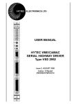
MOD. C117 B
HS CAENET CAMAC
CRATE CONTROLLER
MANUAL REV. 0
CAEN will repair or replace any product within the guarantee period if the Guarantor declares
that the product is defective due to workmanship or materials and has not been caused by
mishandling, negligence on behalf of the User, accident or any abnormal conditions or
operations.
CAEN declines all responsibility for damages or
injuries caused by an improper use of the Modules due
to negligence on behalf of the User. It is strongly
recommended to read thoroughly the CAEN User's
Manual before any kind of operation.
CAEN reserves the right to change partially or entirely the contents of this Manual at any time
and without giving any notice.
Disposal of the Product
The product must never be dumped in the Municipal Waste. Please check your local
regulations for disposal of electronics products.
17/01/96
C117B User's Manual
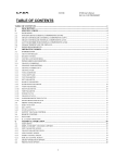
TABLE OF CONTENTS
TABLE OF CONTENTS ..........................................................................................................i
LIST OF FIGURES .................................................................................................................i
LIST OF TABLES....................................................................................................................ii
1. DESCRIPTION .................................................................................................................1
1.1. FUNCTIONAL DESCRIPTION ..........................................................................1
2. SPECIFICATIONS............................................................................................................3
2.1. PACKAGING.....................................................................................................3
2.2. EXTERNAL COMPONENTS.............................................................................3
2.3. POWER REQUIREMENTS ...............................................................................3
3. OPERATING MODES.......................................................................................................5
3.1. H.S. CAENET NETWORK OPERATION...........................................................5
3.2. H.S. CAENET NODE OPERATION...................................................................6
3.3. THE MOD. C117B H.S. CAENET CAMAC CONTROLLER ...............................6
3.4. MOD C117B OPERATING MODES ..................................................................7
3.4.1. MOD C117B RESET .........................................................................7
3.4.2. DATA PACKET STORAGE ...............................................................7
3.4.3. START TRANSMISSION...................................................................8
3.4.4. WAITING FOR THE SLAVE RESPONSE..........................................8
3.4.5. READING THE RESPONSE .............................................................9
3.4.6. ENABLE/DISABLE LAM GENERATION ............................................9
3.5. C117B-SLAVE COMMUNICATION SEQUENCE ..............................................10
4. CAMAC FUNCTIONS .......................................................................................................11
4.1. F(16) N FUNCTION (Write Transmit Data Buffer)..............................................12
4.2. F(0) N FUNCTION (Read Receive Data Buffer).................................................12
4.3. F(17) N FUNCTION (Start Transmission) ..........................................................13
4.4. F(8) N (Test LAM Line)......................................................................................13
4.5. F(9) N, C, Z (Reset Module) ..............................................................................13
4.6. F(24) N (Disable the LAM Generation)...............................................................14
4.7. F(26) N (Enable the LAM Generation) ...............................................................14
5. C.A.E.N. COMMUNICATION PROTOCOL .......................................................................15
5.1. H.S. CAENET NETWORK FOR REMOTING CONTROL ..................................15
5.2. H.S. CAENET NETWORK IMPLEMENTATION: CAEN APPROACH ................15
5.3. MASTER TO SLAVE DATA COMPOSITION ....................................................16
5.4. SLAVE TO MASTER DATA COMPOSITION ...................................................17
5.5. ERROR CODES DESCRIPTION ......................................................................17
APPENDIX A: SOFTWARE BUGS AS OF SEPT. 1992 ..........................................................A.1
APPENDIX B: ELECTRICAL DIAGRAMS ...............................................................................B.1
APPENDIX C: COMPONENT LIST AND LOCATIONS ...........................................................C.1
LIST OF FIGURES
Fig. 1.1: Mod. C117B Block Diagram.......................................................................................2
Fig. 2.1: Mod. C117B Front Panel ...........................................................................................4
i
17/01/96
C117B User's Manual
LIST OF TABLES
Table 4.1: Mod. C117B CAMAC Functions..............................................................................11
Table 5.1: MASTER to SLAVE Data Composition ...................................................................16
Table 5.2: SLAVE to MASTER Data Composition ...................................................................17
Table 5.3: Error Codes ............................................................................................................17
ii
17/01/96
C117B User's Manual
1. DESCRIPTION
1.1. FUNCTIONAL DESCRIPTION
The Model C117B HIGH SPEED (H.S.) CAENET CAMAC CONTROLLER has been
designed to control an H.S. CAENET network through the CAMAC bus. It houses an H.S.
CAENET Node and a Control Logic (microprocessor based) which integrates the functions
of Node controller and Network error handler.
Standard CAMAC functions allow the User to easily control the serial communication on the
H. S. CAENET network according to the typical MASTER/SLAVE communication protocol,
where the CAMAC Crate Controller assumes the MASTER function.
It is composed of a collection of registers for the operation control, and two memory buffers
for the transmitted and received data packets, arranged in a 16 bit FIFO 256 words deep.
When the H.S. CAENET operation fails, the on-board Control logic generates error
messages that are stored in the memory buffer for the received data.
As soon as the data packet (or the error message) is available in the receive buffer, a LAM
signal is generated (if enabled).
The communication line uses a simple 50 Ω coaxial cable as a physical medium.
The data transfer rate is 1 MBaud.
(A functional Block Diagram is shown in Fig. 1.1.)
1
17/01/96
C117B User's Manual
H.S. CAENET NODE
R<1..16>
W<1..16>
TX FIFO
MUX
LOGIC
IB<0..7>
W
R
F(0) N
H.S.
CAENET
F(16) N
SERIAL
INTERFACE
R
50 Ohm
coaxial cable
W
RX FIFO
CAMAC
INTERFACE
F(9) N, C, Z
F(8) N
F(17) N
F(26) N
Front Panel
Push Button
F(24) N
Reset
Set
CONTROL
Rst
F.F.
LAM Line
LOGIC
H.S. CAENET INTERRUPT
Rst
Set
F.F.
Fig. 1.1: Mod. C117B Block Diagram
2
17/01/96
C117B User's Manual
2. SPECIFICATIONS
2.1. PACKAGING
Single width CAMAC module.
2.2. EXTERNAL COMPONENTS
(Refer to Fig. 2.1).
CONNECTORS
- No. 1
"SERIAL LINE" LEMO 00 type, 50 Ω connector;
connector for the H.S. CAENET communication line.
The "DATA" LED is On when the H.S. CAENET Node is active.
DISPLAYS
- No.1
"DATA" red LED;
is On when the H.S. CAENET Node is active.
SWITCHES
- No.1
"RESET" push button; by pushing this button
the C117B enters in restart mode; this causes the following operations:
- the buffers are cleared;
- the LAM is cleared;
- the LAM is disabled;
- every data transfer is aborted;
- the C117B does not accept any commands.
It remains in this status for about 3 msec.
2.3. POWER REQUIREMENTS
+ 6V
1.2 A
3
17/01/96
C117B User's Manual
RESET Push button
RESET
DATA
H.S. CAENET Active LED
SERIAL
LINE
H.S. CAENET Connector
Fig. 2.1: Mod. C117B Front Panel
4
17/01/96
C117B User's Manual
3. OPERATING MODES
3.1. H.S. CAENET NETWORK OPERATION
H.S. CAENET Network is a send and receive half duplex system; it permits asynchronous
serial transmission of data packets along a simple 50 Ω coaxial cable. Several devices (H.S.
CAENET Nodes) are able to share the same media to transmit and receive data.
Each Node is able to receive the serial data packet and store it automatically in the RX FIFO
and transmit the data contained in the TX FIFO (see Fig. 1.1). Both FIFOs are 512 byte
deep.
The H.S. CAENET Node listens for clear coax before transmitting but it is not able to detect
collisions on the cable; for this reason it is important to avoid line contention; i. e., the Nodes
should not attempt to transmit at the same time.
Usually transfers between H.S. CAENET Nodes take place according to the typical
MASTER/SLAVES communication: there is a single H.S. CAENET MASTER that initiates
the transmission, all the SLAVEs receive the data, and only the SLAVE addressed then
accesses the serial line to transmit the data requested by the MASTER.
The maximum data packet length is 512 bytes.
An external clock source provides the basic time reference in the Node: the clock frequency
is three times the data transfer rate. Actually the clock frequency used in the H.S. CAENET
network is 3 MHz (1 MBaud transfer rate);
The Node is seen as an 8 bit peripheral composed of a collection of registers and two
memory buffers arranged in FIFO logic. It generates an interrupt (H.S. CAENET interrupt)
upon:
- the completion of a transmission of a data packet;
- the reception of a data packet;
- when the RX FIFO has been completely unloaded.
5
17/01/96
C117B User's Manual
3.2. H.S. CAENET NODE OPERATION
The basic operation of the H.S. CAENET Node consists in 3 distinct modes:
Transmit, Receive and Restart mode.
- In the Transmit mode the Node accesses the data stored in the TX FIFO and
transmits them on the cable.
- In the Receive mode the serial packet is stored in the RX FIFO.
- In Restart mode the Node does not execute any commands, all the TX and RX
buffers are cleared and the H.S. CAENET interrupt is removed; it remains in this
mode until it detects that the line is clear.
3.3. THE MOD. C117B H.S. CAENET CAMAC CONTROLLER
The Model C117B HIGH SPEED (H.S.)CAENET CAMAC CONTROLLER has been
designed to easily control an H.S. CAENET network through the CAMAC bus. It houses an
H.S. CAENET Node and a Control logic (microprocessor based with dedicated firmware)
that integrates the functions of Node controller with Network error reporting and H.S.
CAENET interrupt handler.
The Control logic directly controls the on-board H.S.CAENET Node. Its multiplexing logic
interfaces the 16 WRITE and READ lines with the two 8 bit FIFOs so that they are seen by
CAMAC as 16 bit wide buffers (Transmit and Receive Data Buffer).
It receives commands from any computer connected to CAMAC In such a way that few
CAMAC Functions allow the User to easily control the serial communication on the H.S.
CAENET network. The communication is performed according to the typical
MASTER/SLAVE communication protocol, where the CAMAC Crate Controller assumes
the H.S. CAENET MASTER function.
It is composed of a collection of registers, for the operation control, and two memory buffers
for the transmitted and received data packets, arranged in a 16 bit FIFO 256 word deep
(see Fig.1.1).
When the H.S. CAENET operation fails, the on-board Control logic generates error
messages that are stored in the Receive Data Buffer.
As soon as the data packet (or the error message) is available in the Receive Data Buffer, a
LAM signal is generated (if enabled).
6
17/01/96
C117B User's Manual
3.4. MOD C117B OPERATING MODES
The following paragraphs describe the various operations that can be performed through
CAMAC to accomplish an H.S. CAENET communication.
3.4.1. MOD C117B RESET
It is possible to reset the C117 B in these ways:
- by performing an F(9) N Function;
- by performing a C Command;
- by performing a Z Command;
- by pushing the Front Panel push button.
After one of these operations the C117B enters in Restart mode; this causes the following
operations:
- the buffers are cleared;
- the LAM is cleared;
- the LAM is disabled;
- every data transfer is aborted;
- the C117B does not accept commands.
It remains in this status for about 3 msec.
3.4.2. DATA PACKET STORAGE
The data to be transmitted are stored in the Transmit Data Buffer by performing one or more
F(16) N Functions with the data asserted on the WRITE lines W<1..16>.
The Q response to the F(16) N Function indicates whether the datum has been stored or not
in the Transmit Data Buffer;
- Q=1:
data has been stored in the Transmit Data Buffer
- Q=0: the Transmit Data Buffer is not available for data storage. This may happen in
the following cases:
- H.S. CAENET Node active (it is transmitting a previous data packet or it is
receiving the SLAVE response data packet);
- Transmit Data Buffer full (the maximum number of data stored is 256).
7
17/01/96
C117B User's Manual
3.4.3. START TRANSMISSION
An F(17) N Function enables the Control logic to transmit on the cable the data packet
stored in the Transmit data buffer.
The logic first check if the Buffer is empty,
- if not, the logic sets the H.S.CAENET Node in the Transmit mode and the data
packet is transmitted on the cable.
- If the Buffer is empty the control logic does not activate the transmission and write
into the Receive data buffer an error code (error %FFFD see Tab. 5.3).
The Q response indicates whether the Start Transmission command has been recognized
or not by the Mod. C117B:
- Q=1 means that the Transmit command has been successfully recognized and that
a valid response can be read in the Receive Data Buffer within a maximum period of
500 msec (SLAVE Response Time-out);
- Q=0 means that the H.S. CAENET Node is not able to transmit data. This may
happen if the H.S. CAENET Node is active (it is transmitting a previous data packet
or it is receiving the SLAVE response).
3.4.4. WAITING FOR THE SLAVE RESPONSE
The Control logic waits for the SLAVE Response for about 500 msec; if no data packet is
received within this period, the Control logic stores an error code (error %FFFF see table
5.3) in the Receive Data Buffer.
If a data packet is received from the cable within the SLAVE Response Time-out, the
Control logic checks if it has the correct header: if not, it first clears the Receive Data Buffer
and then stores an error code in it (error % FFFE see table 5.3).
After these operations the Receive Data Buffer contains valid data (an error code or the
SLAVE response) for the CAMAC Crate Controller that has initiated the H.S. CAENET
Communication.
At this point the Control logic enables the CAMAC reading (Q=1 on F(0) N) and, if the LAM
generation is enabled, a LAM signal is asserted on the CAMAC dataway.
8
17/01/96
C117B User's Manual
3.4.5. READING THE RESPONSE
The User after the Transmission of the data packet expects a response in the Receive Data
Buffer; the content of the Receive Data buffer is read by performing F(0) N Functions (the
required data are present on the READ line R<1..16>).
The presence of valid data can be recognized in two different ways: in polling mode or by
the LAM signal.
Polling mode:
- After the Start Transmission operation the User reads the content of the Receive
Data Buffer by performing F(0) N Functions. The Q response indicates whether the
data read is valid or not.
- Q=1 means valid data;
- Q=0 means no valid data.
- i.e. After the F(17) N Function the F(0) Function must be repeated until a Q=1
response is obtained
LAM signal
- The generation of the LAM signal means that valid data are present in the Receive
Data Buffer
The readout is over when Q=0 (Q STOP readout operation).
The LAM is cleared whenever the last datum has been read.
3.4.6. ENABLE/DISABLE LAM GENERATION
It is possible to enable/disable the C117B LAM generation in the following way:
ENABLE
by performing an F(26) N Function.
DISABLE
by performing an F(24) N Function.
by performing an F(9) N Function;
by performing a C Command;
by performing a Z Command;
by pushing the Front Panel push button "RESET"
At power-on the LAM generation is disabled.
9
17/01/96
C117B User's Manual
3.5. C117B-SLAVE COMMUNICATION SEQUENCE
The operations previously described are summarized in the following report:
- write the data packet in the Transmit Data Buffer; in the packet is contained the H.S.
CAENET address of the SLAVE (see Tab 5.1 for the data structure).
for each data:
- perform an F(16) N Function
- if Q=1
{
the data is stored in the buffer.
}
- else
{
error.
}
- Transmit the data packet:
- perform an F(17) N Function
- if Q=1
{
the C117B H.S. CAENET Node enters in the Transmit mode and the data
packet stored is transmitted on the cable.
}
- else
{
error
}
- Wait for the SLAVE response
- if LAM is enabled
{
wait for C117B LAM: when LAM is asserted go to the Read response section
}
- else
{
- perform an F(0) N Function
- if Q=0 discard the data and repeat the operation
- if Q=1 accept the data read: it may be the first data of the SLAVE response
data packet or a Control Logic error message; go to the Read Response
section
}
- Read response
- perform an F(0) N Function
- if Q=1 accept the data read and repeat the operation
- if Q=0 discard the data read and exit: the Receive Data Buffer is empty .
10
17/01/96
C117B User's Manual
4. CAMAC FUNCTIONS
The standards CAMAC functions listed in Table 4.1 allow the User to perform the required
control and setting operations on each SLAVE in the H.S. CAENET network.
X response is generated for all valid function.
Q response is generated for each valid function unless is otherwise specified.
Table 4.1: Mod. C117B CAMAC Functions
F(0) N
F(8) N
F(9) N
F(16) N
F(17) N
F(24) N
F(26) N
C, Z
Reads the data stored in the Mod. C117B
Receive Data buffer. Q response while the
buffer contains data.
Tests the LAM line. Q response if LAM is
true.
Resets the module (clears buffers and LAM,
disables the LAM line, aborts data transfer).
Stores the data into the Mod. C117B
Transmit Data buffer. Q response until the
buffer is full (256 16-bit words).
The Transmit data buffer content is
transmitted on the cable.
Disables the LAM line.
Enables the LAM line.
Same as F(9) N.
11
17/01/96
C117B User's Manual
4.1. F(16) N FUNCTION (Write Transmit Data Buffer)
The Transmit Data Buffer is the buffer that is loaded with the data packet to transmit, it is
arranged in a FIFO logic 16 bit wide (the data packet transmitted is composed of 16 bit
words as shown in Tab 5.1).
The data are stored in this buffer by performing one or more F(16) N Functions with the data
to be written asserted on the WRITE lines W<1..16>.
The Q response to the F(16) N Function indicates if the datum has been stored or not in the
Transmit Data Buffer;
- Q=1:
the data has been stored in the Transmit Data Buffer
- Q=0: the Transmit Data Buffer is not available for data storage. This may happen in
the following cases:
- H.S. CAENET Node active (it is transmitting a previous data packet or it is
receiving the SLAVE response data packet);
- Transmit Data Buffer full (the maximum number of data stored is 256)
4.2. F(0) N FUNCTION (Read Receive Data Buffer)
The Receive Data Buffer is the buffer where the H.S. CAENET Node automatically stores
the data packet received from the SLAVE, or, where The Control Logic stores the error
codes (if the H.S. CAENET operation has failed). It is arranged in a FIFO logic 16 bit wide
(the data packet received is composed of 16 bit words as shown in Tab 5.1). The data
contained in the Receive Data buffer are read by performing F(0) N Functions.
The required data are present on the READ line R<1..16>.
The Q response indicates if the data read is valid or not.
- Q=1:
valid data;
- Q=0:
no valid data.
12
17/01/96
C117B User's Manual
4.3. F(17) N FUNCTION (Start Transmission)
The F(17) N Function enables the C117B Control Logic to transmit on the cable the data
stored in the Transmit Data Buffer. If this operation is performed with the Transmit Data
Buffer empty, the Control logic stores an error message in the Receive Data Buffer (error
FFFD see Table 5.3).
The Q response indicates if the Start Transmission command has been recognized or not
by the Control Logic:
- Q=1 means that the Transmit command has been successfully recognized and that a
valid response will be available in the Receive Data Buffer within a period of 500
msec (the C117B Control Logic waits up to 500 msec for the SLAVE response; If no
data packet is received by this period it stores in the Receive Data Buffer the error
code %FFFF, see Table 6.21).
- Q=0 means that the H.S CAENET Node is not able to transmit data. This may
happen if the H.S. CAENET Node is active (it is transmitting a previous data packet
or it is receiving the SLAVE response).
4.4. F(8) N (Test LAM Line)
The Q response to this CAMAC Function allows to test the LAM line:
- Q=1:
LAM asserted
- Q=0:
LAM not asserted
4.5. F(9) N, C, Z (Reset Module)
The CAMAC C and Z commands and the F(9) N Function cause the C117B to enter in
Restart mode; this produces the following operations:
- the buffers are cleared;
- the LAM is cleared;
- the LAM is disabled;
- every data transfer is aborted;
- the C117B does not accept commands.
It remains in this status for about 3 msec.
13
17/01/96
C117B User's Manual
4.6. F(24) N (Disable the LAM Generation)
This CAMAC Function disables the LAM generation; this means that, when the Control
Logic enables the CAMAC reading (at the end of a data packet reception) the LAM signal
will not be generated.
4.7. F(26) N (Enable the LAM Generation)
This CAMAC Function enables the LAM generation; this means that, when the Control Logic
enables the CAMAC reading (at the end of a data packet reception) the LAM signal will be
asserted.
This function must be performed after the Power-on or after a Reset operation (C, Z, F(9)N
and the pressing of the Front Panel push button), because these operations disable the
LAM generation.
14
17/01/96
C117B User's Manual
5. C.A.E.N. COMMUNICATION PROTOCOL
5.1. H.S. CAENET NETWORK FOR REMOTING CONTROL
H.S. CAENET provides a unique way of remotely controlling "passive" electronic modules;
modules that have not been designed for specific data acquisition purposes, and therefore
have no access to any bus like CAMAC or VME.
NIM modules (Delay Units, Attenuators, Amplifiers, I/O registers) as well as H. V. Supplies
have several parameters which need to be adjusted under computer control; many CAEN
units house an H.S. CAENET Node inside the module that allows the possibility of linking
several devices of different types and functionality with a central controller.
5.2. H.S. CAENET
APPROACH
NETWORK
IMPLEMENTATION:
CAEN
CAEN has developed a transmission protocol via H.S. CAENET line that permits the
monitoring and control of many CAEN units from a single controller. This network has the
following structure and protocol:
The transfers between H.S. CAENET Nodes take place according to the typical
MASTER/SLAVEs communication:
- There is a single MASTER: H.S. CAENET Controller
- The SLAVEs are daisy chained on the network, and are identified by an address
code (from 0 to 99); the address is usually selectable via thumb-wheel switch located
on the Front panel of the module.
- the H.S. CAENET MASTER starts the transmission, all the SLAVEs receive the
data, and only the addressed SLAVE then accesses the serial line to transmit the
data requested by the MASTER.
In this way is possible from a single point it to control up to 100 SLAVEs.
15
17/01/96
C117B User's Manual
5.3. MASTER TO SLAVE DATA COMPOSITION
The MASTER-to-SLAVE data have to be written into the Transmit Data buffer by performing
subsequent F(16) N functions as follows:
Table 5.1: MASTER to SLAVE Data Composition
Order
CAMAC
Function
W16 to W1
(HEX)
1
F(16) N
%0001
2
3
F(16) N
F(16) N
%00XX
Code
4 to 256
F(16) N
Set
Meaning
H. S. CAENET Controller
identified code
Crate Number
Code of the operation to
be performed
Eventual set values
In the C117 B Receive Data Buffer the User reads the SLAVE response or a C117B error
message (for example if the C117 B does not receive any SLAVE response within a period
of 500 msec it stores the code %FFFF in the Buffer; see Tab. 5.3).
16
17/01/96
C117B User's Manual
5.4. SLAVE TO MASTER DATA COMPOSITION
The answer data coming from the SLAVE or a Control Logic error message is stored into
the C117B Receive Data buffer. The User can get it by performing subsequent F(0) N
Functions. The following Table shows the structure of the SLAVE data packet:
Table 5.2: SLAVE to MASTER Data Composition
Order
1
2 to 255(*)
CAMAC
Function
F(0) N
F(0) N
Datum
Meaning
Error Code
value
Error code
Eventual Parameter value
(*) The first data of the packet is read and checked by the Control Logic as shown in §3.4.4.
The Error codes are described in Tab. 5.3.
5.5. ERROR CODES DESCRIPTION
The Error codes are described in the following Table:
Table 5.3: Error Codes
Datum
(Hex)
Meaning
%0
%FFFD
Successful operation. SLAVE message.
No data to be transmitted; it has tried to start a transmission with
the Transmit data Buffer empty (Control logic error message).
The H.S. CAENET Controller identifier is incorrect (Control Logic
error message).
The addressed SLAVE does not exist. This message are generated after a period of 500 msec (Control Logic error message).
%FFFE
%FFFF
All the other possible error codes from the SLAVE module have the format "%FFnn" where
"nn" can be any number.
17
17/01/96
C117B User's Manual
APPENDIX A: SOFTWARE BUGS AS OF SEPT. 1992
This appendix contains the software bugs recognized as of September 1992.
If one of the SLAVE in the H.S. CAENET Network has the address code = 0 the Network
communications do not work.
Do not use SLAVE address code = 0.
A.1
17/01/96
C117B User's Manual
APPENDIX B: ELECTRICAL DIAGRAMS
B.1
17/01/96
C117B User's Manual
APPENDIX C: COMPONENT LIST AND LOCATIONS
C.1