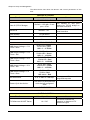
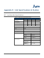
1
ACU202R01 Agilis Control Unit (Outdoor Quad Band LNB Controller) Installation and Operation Manual IM02960168 Rev.C Reliability Choice Innovation Copyright Notice All information contained in this Manual are the property of ST Electronics (Satcom & Sensor Systems) Pte. Ltd. The Manual in whole or in part, may not be duplicated or reproduced without the written permission of ST Electronics (Satcom & Sensor Systems) Pte. Ltd. The Manual is intended to be used as a guide only and may be revised, modified or altered at any time by ST Electronics (Satcom & Sensor Systems) Pte. Ltd. ST Electronics (Satcom & Sensor Systems) Pte. Ltd. shall not be liable to users of the Manual nor to any other person, firm, company or other body for any loss, direct, indirect or consequential, in contract or in tort of for any negligent mis-statement or omission contained herein, by reason of, arising from or in relation to any such user, other person, company or body relying or acting upon or purporting to rely or act upon any matter contained in this Manual. If you have any enquiry or require further technical assistance, please contact our Customer Service Centre at: ST Electronics (Satcom & Sensor Systems) Pte. Ltd. No. 29 New Industrial Road, ST Electronics Paya Lebar Building Singapore 536213 Hotline: +65 65217959 Fax: +65 65217333 E-mail: [email protected] Website: www.agilissatcom.com © 2011 ST Electronics (Satcom & Sensor Systems) Pte. Ltd. All Rights Reserved. Table of Contents Chapter 1 Product Overview............................................................................................. 1 1.1 About the ACU Series Agilis Control Unit ....................................................... 1 1.2 ACU Functions ....................................................................................... 2 1.2.1 ACU Functional Block Diagram.......................................................... 2 1.2.2 ACU Functions ............................................................................. 2 1.2.3 Receive Path............................................................................... 3 1.2.4 Transmit Path (Optional) ................................................................ 3 1.2.5 LED Status Display ........................................................................ 3 1.2.6 SUPPLY VOLTAGE OPTIONS .............................................................. 3 1.3 ACU Interfaces..................................................................................... 4 1.3.1 ACU Front View ........................................................................... 4 1.3.2 ACU Right Side View...................................................................... 6 1.3.3 ACU Left Side View ....................................................................... 7 1.4 Product Models...................................................................................... 7 Chapter 2 System Configurations ....................................................................................... 9 2.1 Types of System Configurations .................................................................. 9 2.1.1 LNB Standalone System Configuration using ACU .................................... 9 2.2 System Components ...............................................................................10 2.2.1 Low Noise Block (LNB) ..................................................................10 2.2.2 Transient Protection Box ...............................................................11 Chapter 3 Installation....................................................................................................13 3.1 Unpacking the Box.................................................................................13 3.2 Pre-Installation Preparations ....................................................................14 3.2.1 Environmental Considerations .........................................................14 3.2.2 Tools Required ...........................................................................14 3.2.3 Site Preparation Checklist ..............................................................14 3.2.4 Power Supply .............................................................................15 3.2.5 Pre-Installation Test.....................................................................16 3.2.6 Sealing .....................................................................................17 Chapter 4 Setup and Management.....................................................................................19 4.1 Monitor & Control..................................................................................19 4.2 Monitor & Control Specifications................................................................19 Chapter 5 Maintenance..................................................................................................27 5.1 Preventive Maintenance ..........................................................................27 5.2 Maintenance Procedure...........................................................................27 5.2.1 Receive Gain Testing ....................................................................27 5.2.2 Water Leakage Protection..............................................................28 5.2.3 Completing the Maintenance ..........................................................28 Appendix A Customer Service ............................................................................................29 A.1 Warranty Information .............................................................................29 A.2 Return Material Authorization (RMA) ...........................................................30 A.3 Additional Technical Support ....................................................................31 Appendix B Unit Specifications & Outline..............................................................................33 B.1 Low Noise Block Specifications ..................................................................33 B.2 Unit Outline Drawings.............................................................................34 IM02960168 Rev.C i Appendix C Compliance Standards ......................................................................................35 Appendix D Document Revision Log .....................................................................................36 ii IM02960168 Rev.C List of Figures Figure 1.1 Agilis Control Unit Functional Block Diagram ............................................................ 2 Figure 1.2 Front view of the ACU unit.................................................................................. 4 Figure 1.3 Right side view of the ACU unit ............................................................................ 6 Figure 1.4 Left side view of the ACU unit ............................................................................. 7 Figure 2.1 Standalone LNB Configuration Setup using ACU ......................................................... 9 Figure 2.2 Low Noise Block (LNB) ......................................................................................10 Figure 2.3 Transient Protection Box ...................................................................................11 Figure 3.1 Sealing the connectors .....................................................................................17 Figure 4.1 OMC500 v1.0.0 screenshot .................................................................................20 Figure B-1 ACU Outline Drawing........................................................................................34 Figure B-2 LNB drawing ..................................................................................................34 IM02960168 Rev.C iii List of Tables Table 1-1 Interfaces present on the front of the ACU Unit ........................................................ 4 Table 1-2 Pin-out configuration for RS485 connector ............................................................... 5 Table 1-3 Pin-out configuration for RS232 connector ............................................................... 5 Table 1-4 Interfaces present on the right side of the ACU unit ................................................... 6 Table 1-5 Pin-out configuration for Ethernet Switch connector................................................... 6 Table 1-6 Interfaces present on the left side of the ACU unit..................................................... 7 Table 1-7 Product series models ....................................................................................... 7 Table 2-1 List of accessories and components for LNB redundant system....................................... 9 Table A-1 Pre-RMA Request Checklist.................................................................................30 Table B-1 Quad Band Ku-Band LNB Specifications ..................................................................33 iv IM02960168 Rev.C Chapter 1 Product Overview Agilis, a global leader in the design, development and manufacturing of quality satellite products for various applications, introduces the Agilis ACU Series Agilis Control Unit. The ACU Series Agilis Control Unit is designed to provide a complete monitor and control solution for outdoor Low Noise Block (LNB) applications. This user manual provides detailed information to system integrators and end users on how to set-up, operate and maintain the ACU Series Agilis Control Unit. 1.1 About the ACU Series Agilis Control Unit The Agilis Control Unit (ACU) is a high performance, cost-effective VSAT equipment designed for satellite communication with high speed transmission capability suitable for both telephony and high speed data communication. The ACU can be operated with different modulation formats like BPSK, QPSK and FM. The Agilis Control Unit is suitable for the following applications: Single Carrier Per Channel (SCPC) Multi-Carrier Per Channel (MCPC) Demand Assigned Multiple Access (DAMA) Time Division Multiple Access (TDMA) The ACU is designed for outdoor environment operating conditions, with Ntype (F) and Mil-Specs connectors. IM02960168 Rev.C 1 Chapter 1 Product Overview 1.2 ACU Functions This section explains the design and functions of the Agilis Control Unit. 1.2.1 ACU Functional Block Diagram Figure 1.1 Agilis Control Unit Functional Block Diagram 1.2.2 ACU Functions The main function of the ACU is to provide complete monitoring and control functions to outdoor LNBs. The ACU functions include: Provides a +13/+18 VDC supply for the LNB. Provides a 22 kHz tone for the LNB operation. Provides a 10MHz reference for the LNB through a very stable builtin stable 10 MHz OCXO. Monitor and control The M&C module is the central processing hub of the ACU. It is developed on an embedded microcontroller to perform the required monitoring and control functions. The unit can be connected to a remote PC via serial communication using RS485 or through optional Ethernet connection. Using the M&C module, you can: 2 Configure the unit’s operating parameters. Monitor the unit’s operating parameters. Check alarm status. IM02960168 Rev.C Chapter 1 Product Overview 1.2.3 Receive Path On the receive path, the Modem Rx is connected to the “Rx L-BD OUT” port and the LNB connected to the “Rx L-BD IN” port. The OCU will provide DC (13 / 18V), 10 MHz REF and 22 KHz tone to the LNB. When using the SMW LNB, the OCU will provide selectable DC (OFF / 13 / 18VDC) and 22 KHz (on / off) and multiplex them onto the “Rx L- BD IN” port. The OCU will provide a 10MHz REF signal on the “REF OUT” port which will be connected to the SMW LNB. When using the Agilis LNB, the OCU will provide selectable DC (OFF / 13 / 18VDC) and 10 MHz (on / off) and multiplex them onto the “Rx L-BD IN” port. If the Modem internal 10 MHz reference source is enabled, the OCU will filter off this 10 MHz reference source from the modem. The OCU will also provide a “Rx L-BD OUT MON” port to monitor the receive signal. 1.2.4 Transmit Path (Optional) On the transmit path, the modem Tx is connected to the “Tx L-BD IN” port and the BUC connected to the “Tx L-BD OUT” port. The DC for the BUC is provided either by the modem on the transmit cable or by the External DC source on the “TX DC IN” port. The OCU allows both L-band signal and DC to be transmitted to the BUC. If the BUC does not require external DC to power up, the OCU will allow the user to block any DC on the “Tx L-BD OUT” port. 1.2.5 LED Status Display The OCU shall provide visual status indications for the following parameters: Power Supply Tx Status DC (Off / Modem / Ext.) 10 MHz (On / Off) Rx Status DC (Off / 13V / 18V) 10 MHz (On / Off) 22 KHz (On / Off) LNB Status The OCU shall provide selectable DC, 22 KHz tone and 10 MHz REF via Ethernet M&C. 1.2.6 SUPPLY VOLTAGE OPTIONS The ACU unit derives its voltage supply through the separate AC connector. IM02960168 Rev.C AC Input: Voltage range is 110 ~ 240 VAC @ 50/60 Hz 3 Chapter 1 Product Overview 1.3 ACU Interfaces 1.3.1 ACU Front View Figure 1.2 Front view of the ACU unit Table 1-1 Interfaces present on the front of the ACU Unit Port Reference Connector Type Signal Details AC IN 3-pin, plug KPT02E12-3P AC IN is the primary AC power supply input which provides an AC supply for built-in power supply (250W AC-DC converter). FUSE - 5A AC~250V fuse inside for the AC1 IN power supply. RS232 8-pin square flange KPT02E12-8S Provides an RS232 interface for an indoor DTE (usually a PC) to monitor and control the ACU operation. RS485 8-pin square flange KPT02E12-8S Provides an RS485 interface for an indoor DTE (usually a PC) to monitor and control the ACU operation. LED STATUS INDICATORS LED Condition LED Color PSU Power ON GREEN RX REF 10MHz Power ON GREEN TX REF Tx Ref OFF RED Tx Ref ON GREEN “0V” Set LED OFF “+13V” Set GREEN “+18V” Set BLUE 22KHz Tone OFF RED 22KHz Tone ON GREEN TX DC (w/o TX DC) LED OFF LNB STATUS LNB connected and RX DC ON GREEN RX DC 22KHz TONE 4 IM02960168 Rev.C Chapter 1 Product Overview The following tables provide the pin-out details of the M&C connectors. Table 1-2 Serial Table 1-3 Serial IM02960168 Rev.C Pin-out configuration for RS485 connector Pin Function Pin B Ground Pin E RS485- Pin F RS485+ Pin A Reserved Pin C Reserved Pin G Reserved Pin H Reserved Pin D Reserved Pin-out configuration for RS232 connector Pin Function Pin B Ground Pin E RS232-RX Pin F RS232-TX Pin A Reserved Pin C Reserved Pin G Reserved Pin H Reserved Pin D Reserved 5 Chapter 1 Product Overview 1.3.2 ACU Right Side View Figure 1.3 Right side view of the ACU unit Table 1-4 Port Reference Connector Type Signal Details RX L-BD MON 50 Ω female Ntype connector L-Band output coupled signal for monitoring. ETHERNET SWITCH 8-pin square flange KPT02E12-8S Provides an Ethernet interface for an indoor DTE (usually a PC) to monitor and control the ACU operation. RX L-BD OUT 50 Ω female Ntype connector Connects to the indoor unit (modem). RX L-BD IN 50 Ω female Ntype connector Connects to the LNB and provides the LNB with DC power and 22KHz tone. REF OUT 50 Ω female Ntype connector Provides signal. Table 1-5 Ethernet 6 Interfaces present on the right side of the ACU unit OUT 10MHz reference Pin-out configuration for Ethernet Switch connector Pin Function Pin A Reserved Pin D Reserved Pin F Reserved Pin H Reserved Pin G TX+ Pin E TX- Pin C RX+ Pin B RX- IM02960168 Rev.C Chapter 1 Product Overview 1.3.3 ACU Left Side View Figure 1.4 Left side view of the ACU unit Table 1-6 Interfaces present on the left side of the ACU unit Port Reference Connector Type Signal Details TX L-BD (Optional) OUT Dummy Plate Not Used TX L-BD (Optional) IN Dummy Plate Not Used TX DC (Optional) IN Dummy Plate Not Used 1.4 Product Models This manual is suitable for the ACU models: Table 1-7 IM02960168 Rev.C Product series models Model Type Model # ACU Series Outdoor LNB Control Unit ACU202R01 7 Chapter 1 Product Overview ---This page is intentionally left blank--- 8 IM02960168 Rev.C Chapter 2 System Configurations This chapter explains, in detail, the system in which the ACU is deployed in and its various components. 2.1 Types of System Configurations The ACU can be deployed in a Standalone System Configuration. The Standalone System Configurations is explained in the details below. 2.1.1 LNB Standalone System Configuration using ACU Figure 2.1 Standalone LNB Configuration Setup using ACU The table below lists the accessories and components required to setup the Standalone LNB System. This setup diagram and table can also be found at the back of this manual for your convenience. Table 2-1 IM02960168 Rev.C List of accessories and components for LNB redundant system Item No. Agilis Part No. Description Length (m) Quantity 1 1001520980 AC Power Cable with Transient Protection Box 2 1 2 6103480008 Converter RS485 to USB - 1 3 2502040699 C/A M&C (optional) - 1 4 2502040500 C/A M&C RS232 - 1 5 2502041166 C/A M&C DB9 to ETH RJ45 (optional) A - RF Cable (L-Band) To be arranged by customer - ACU202R01 Agilis Control Unit - RS485 1 9 Chapter 2 System Configurations Item No. Agilis Part No. Description Length (m) Quantity - - QUAD-BAND LNB - 1 Note: The table above is a typical accessories list for the Standalone LNB System. Depending on your purchase order, your Standalone LNB System package may not include certain optional cables. Please contact Agilis if you wish to purchase any of the above accessories. 2.2 System Components This section explains the various system components, aside from the ACU, that are required to setup the entire system. 2.2.1 Low Noise Block (LNB) LNBs are mounted near the reflector dish. Wide bands of frequency signals are fed into the LNB which then amplifies and converts these signals to minimize signal loss. Agilis’ LNB devices are specially designed for satellite earth station receiver front ends and other applications. Figure 2.2 Low Noise Block (LNB) 10 IM02960168 Rev.C Chapter 2 System Configurations 2.2.2 Transient Protection Box Transient protection prevents spikes in electrical discharges that may cause damage to your Agilis equipment or other connected components. A TPB is connected to AC input ports of your Agilis equipment. Figure 2.3 Transient Protection Box For the TPB to work effectively, please keep clean outgoing lines away from the incoming or earth leads. Note: Ground the TPB by connecting the M6 Earth Stud to a grounding rod. Note that this is vital to the proper operation of the TPB. IM02960168 Rev.C 11 Chapter 2 System Configurations ---This page is intentionally left blank--- 12 IM02960168 Rev.C Chapter 3 Installation This chapter explains a step-by-step process to safely mount and install your Agilis products. WARNING: Always handle the ACU with care. Dropping or knocking it may cause damage to the unit. Agilis’ warranty does not extend to defects due to excessive shock or vibration. 3.1 Unpacking the Box Before unpacking the box, check if it had been damaged or opened. If the shipment may have been tempered with, open the box in front of a representative from the shipping company. Upon opening the box, carefully remove the items in the package and check them against the packing list. If any of the items are damaged or missing, please contact Agilis or your local Agilis representative before proceeding. We recommend that you keep the original packing materials until you have completed the checks and confirmed that the unit is in working order. If you need to repack the product for shipping, please use the original shipping container and packing materials whenever possible. Alternatively, you may also use high quality commercial packing materials to repack the unit. Please seal the container firmly and clearly mark “FRAGILE Electronic Equipment” on the exterior. IM02960168 Rev.C 13 Chapter 3 Installation 3.2 Pre-Installation Preparations 3.2.1 Environmental Considerations The Outdoor unit’s aluminium chassis is coated with white, enamelled epoxy for environmental protection. All interface connectors are sealed to prevent air and moisture from entering the unit. According to the instructions supplied by the antenna manufacturer, locate and install the antenna in an area that is free from RF interference from motors and electronic equipment. A clear line of sight from the antenna to the satellite is essential. To ensure safety and protection of personnel and equipment, lightning arresters should also be used at the site. Size 3/0 or 4/0 stranded copper wire should be used to bond the ACU and LNB to the antenna frame and to the lightning protection ground rod. The grounding resistance of the antenna should not be more than 10 Ω. Before proceeding with the mounting process, please ensure that the environmental conditions in the area where the ACU is to be mounted is appropriate for its optimal operation. These include: Temperature: -40ºC to +60ºC Relative Humidity: Up to 100% Weather protection sealed to IP65 3.2.2 Tools Required We highly recommend having the following tools on hand before starting the installation: 1 complete set of socket wrench 1 Philips head screwdriver 1 cutter 1 bag of cable ties (long and medium length) 1 multi-meter 3.2.3 Site Preparation Checklist The following table provides a checklist to help you ensure that your site is adequately equipped to perform the installation. Checklist Item 14 Y/N Equipment required for site survey Inclinometer Compass / DataScope 1-meter rectangular bar Scientific calculator 100-meter measuring tape Site location map GPS receiver Road distance wheel Vernier calliper Location markers / flags Is site in the satellite footprint? Yes No IM02960168 Rev.C Chapter 3 Installation Checklist Item Y/N Approximate length of cables between ODU and IDU IF cable routing method Underground Surface Is there a clear path for cables from ODU to IDU? Yes No Proposed mounting location Antenna structure Near the antenna Inside the shelter Other: ________________ Does the mounting location provide the best route for cables from IDU to ODU to antenna? Yes No Is there an unobstructed view from the satellite(s) of interest? Yes No Are there any hazards near the site location that may damage or obstruct the ODU? (old buildings, trees, planned future construction) Yes No If yes, please specify: ____________________________ Are there possible RF interference from other nearby telecommunication towers? Yes No Will your installation cause interference to other nearby setup? Yes No Is sufficient power supply available? Yes No Is grounding available? Yes No Is the site prone to the following? Heavy wind Heavy rainfall Ice/snow accumulation Extreme temperatures Sand/Dust storms Others: ______________ 3.2.4 Power Supply SELECTING AN APPROPRIATE AC POWER SOURCE When selecting the AC power source to connect your indoor and outdoor units, please ensure that the voltages are within the limits specified in the table below. You are recommended to use an Automatic Voltage Regulator if your power source falls outside of these limitations. Tolerance X VAC, where X is the AC requirement of the device Live Neutral 230 VAC ± 15% Live Earth 230 VAC ± 15% Neutral Earth < 5 VAC Note: The equipment may be damaged if the Neutral Earth tolerance exceeds 5VAC. Please check your grounding setup if this occurs. IM02960168 Rev.C 15 Chapter 3 Installation 3.2.5 Pre-Installation Test Performing a pre-installation test prior to the actual field installation helps you to: Confirm that the unit has not been damaged during shipment. Check that the unit is in working order before performing a tiring and costly mounting procedure on your antenna. The downlink test procedure is recommended for the ODU ACU System. Note: Ensure that no alarm or fault appears on the ACU before performing any test. DOWNLINK TEST PROCEDURE Step 1 Connect the ACU as shown in the figure below and power up the system. Step 2 Use the Ku band signal generator to input a Ku-Band pure carrier to Quadband LNB. Adjust the RF output power to -60dBm. Step 3 Measure L band Signal level at the “Rx L-band Out Mon.” port by a spectrum analyzer. Calculate the receive gain by subtracting the input power from the output power plus the amount of attenuation included in this link. Compare the gain obtained with the specifications of LNB. If there is no signal, check if the channel setting is correct. Example: Rx gain = IF OUT power - RF IN power + Attenuation Set = -10 - (-60) +0 = 50 dB 16 IM02960168 Rev.C Chapter 3 Installation 3.2.6 Sealing To complete an installation, seal up all the connectors and waveguide joints of the system using self-amalgamating tape. It is recommended that all “sealing job” be done after the system has been verified to be operational. The following points should be taken care of: Step 1 Make sure that all the connectors are hand-tightened before sealing. Step 2 The sealing must cover from the housing of the ACU until after the heatshrink sleeve. Refer the Figure 3.1 for the sealing. Step 3 All the unused connectors must be covered with a cap and sealed. CONNECTOR HOUSING Step 4 Make sure all waveguide joints are properly sealed with an appropriate gasket. Figure 3.1 Sealing the connectors IM02960168 Rev.C 17 Chapter 3 Installation ---This page is intentionally left blank--- 18 IM02960168 Rev.C Chapter 4 Setup and Management 4.1 Monitor & Control The ACU can be monitored and controlled remotely via the OMC500 v1.0.0 software. This chapter provides information about the monitor and control specifications of the ACU. Figure 4.1 Connecting the ACU to the PC via RS232 serial connection 4.2 Monitor & Control Specifications The tables below lists down the Monitor and Control parameters of the ACU. SERIAL-INTERFACE Test Parameter GUI Software Value / Specification Remarks OMC500 v1.0.0 This software will provide the GUI to monitor and control OCU using Serial Interface RS232 PORT Baud rate of RS232 communication 9600 LED display on GUI Same as LED display on Unit It will follow the layout the LED display ont eh front-panel on the physical unit RS485 - TCPIP BRIDGE TCIP/UART Baud rate in OMC500 Default Host IP IM02960168 Rev.C 9600 192.168.1.3 and port = 9761 19 Chapter 4 Setup and Management The Agilis OMC500 software allows you to monitor and control the ACU and LNB parameters via serial communication. This package comes in an executable file that can be launched once the ACU has been physically connected to the PC using either a RS232 cable or a RS485 cable. Refer to Figure 2.1 Standalone LNB Configuration Setup using the ACU for the cable details. To launch the Agilis OMC Software package, unzip the .zip file that is included in your system purchase. Double-click the ”OMC500_v1.0.0.P.exe” to launch the monitor and control software. Figure 4.2 OMC500_v1.0.0.P.exe Once the OMC500 Software is successfully launched, you will see the interface where you can monitor and control the parameters of the ACU. The correct COM Port of the ACU must be entered on the “COM:” textbox to enable the PC to communicate with the ACU. The graphical user interface consists of buttons, drop-downs, textboxes, and graphical displays that show the parameters of the ACU that can be viewed and/or configured. Figure 4.3 OMC500 Graphical User Interface 20 IM02960168 Rev.C Chapter 4 Setup and Management Shown below are several parameters of the ACU that can be configured using the OMC500. Figure 4.4 Attenuation Adjustment Figure 4.5 L BAND IN ON/OFF If the ACU is not connected or the incorrect COM port has been entered on the textbox, an error message will pop-up on the screen. Refer to the figure shown below. Figure 4.6 ACU operation error IM02960168 Rev.C 21 Chapter 4 Setup and Management The tables below lists down the Monitor and Control parameters of the ACU. MONITOR & CONTROL Test Parameter Value / Specification Remarks DEVICE INFORMATION Host IP (TCP/IP Bridge) Default = 192.168.1.3 and port = 9761 Device ID DEFAULT = 01 Part Number 15 Characters Serial Number 16 Characters Firmware Version 4 Characters The default IP and port setting for TCP/IP bridge on the serial interface Identifies the device on RS485 serial interface DEVICE CONFIGURATION LNB Output Voltage = 13 V Tone = None Rx DC LED = Green 22 KHz LED = Red LNB L.O = 9.75GHz LNB Output Voltage = 13 V Tone = 22K Rx DC LED = Green 22 KHz LED = Green LNB L.O = 10.0GHz LNB Output Voltage = 18 V Tone = None Rx DC LED = Blue 22 KHz LED = Red LNB L.O = 11.05GHz LNB Output Voltage = 18 V Tone = 22K Rx DC LED = Blue 22 KHz LED = Green LNB L.O = 10.5GHz LNB Output Voltage = 0 V Tone = None Rx DC = Off 22 KHz = Red LNB status = Red Rx Attenuation Power-Cycle the device. 0 to 15 dB in 0.5 dB step The supported RX attenuation range and step size The device is powered-back with the last configured state DEVICE STATUS MONITOR & CONTROL Test Parameter Tx Reference ON/OFF Status 22 Value / Specification On / Off Remarks This would indicate the presence or absence of TX Reference signal IM02960168 Rev.C Chapter 4 Setup and Management Rx MUX Ref ON/OFF Status On / Off This would indicate the presence or absence of RX Reference on the MUX LNB ON/OFF Status On / Off This would indicate the status of LNB LNB Status OK / Alarm This would indicate the health of the LNB Tx Reference Status OK / Alarm This would indicate the health of the TX Reference Rx Reference Status OK / Alarm This would indicate the health of the RX Reference SNMP-INTERFACE Test Parameter Value / Specification Remarks SYSTEM INFO 01. System Description (sysDescr) Agilis Outdoor Control Unit 02. System Uptime (sysUpTime) 03. System Contact (sysContact) 04. System Name (sysName) 05. System Location (sysLocation) Read-Write Read-Only Customer-Service +6565217959 Read-Write ACUX Outdoor Control Unit Read-Write ST Electronics, Singapore Read-Write DEVICE INFO 06. Manager IP (managerIP) Default = 192.168.1.10 Read-Write 07. Device IP (deviceIP) Default = 192.168.1.3 Read-Write 08. Device ID (deviceID) Default = 01 Read-Write 09. Part Number (partNo) 15 Characters Read-Only 10. Serial Number (serialNo) 16 Characters Read-Only 11. Firmware Version (firmwareVersion) 4 Characters Read-Only DEVICE STATUS 12. Tx DC ON / OFF Status (tx_DCOut_Status) NA Read-Only 13. Tx Reference ON / OFF Status (tx_REFOut_Status) On / Off Read-Only 14. Rx MUX Ref ON / OFF Status (rx_MUXREFOut_Status) On / Off Read-Only 15. LNB ON / OFF Status (lnb_Out_Status) On / Off Read-Only IM02960168 Rev.C 23 Chapter 4 Setup and Management DEVICE ALARM 16. LNB Status (lnb_Alarm) OK / Alarm Read-Only N.A Read-Only 18. Tx Reference Status (tx_REF_Alarm) OK / Alarm Read-Only 19. Rx Reference Status (rx_REF_Alarm) OK / Alarm Read-Only 17. Tx DC Status (tx_DC_Alarm) DEVICE CONFIGURATION 20. Tx Reference ON/OFF (tx_REF_Switch) On / Off Read-Write 21. Rx Reference ON/OFF (rx_REF_Switch) On / Off Read-Write 0 to 15 dB in 0.5 dB step Read-Write Enable / Disable Read-Write 13V / 18V Read-Write 22. Rx Attenuation (rx_Atten) 23. LNB Output Tone (lnb_Out_Tone) 24. LNB Output Voltage (lnb_Out_Voltage) WEB-INTERFACE Test Parameter Value / Specification Remarks DEVICE INFORMATION 01. Part Number ACU202R01 02. Serial Number 03. Firmware Version NETWORK INFORMATION 04. Device ID Default = 01 05. Device IP Default = 192.168.1.3 06. SNMP Manager IP Default = 192.168.1.10 DEVICE STATUS 07. Tx DC Ouput NA 08. Tx Reference Output On / Off 09. Rx Reference Output On / Off 10. LNB Voltage 11. LNB Tone 12. Rx Attenuation 13. LNB Output 13V or 18V On / Off 0 to 15 dB in 0.5 dB step On / Off DEVICE ALARM 14. LNB Status 24 OK / Alarm IM02960168 Rev.C Chapter 4 Setup and Management 15. Tx DC Status NA 16. Tx Reference Status OK / Alarm 17. Rx Reference Status OK / Alarm DEVICE CONFIGURATION 18. Login ID 19. Login Password 20.Verify whether user control functions are blocked with ANY OTHER password 21. Device IP “admin” “sttest ” ID = Guest; Password = Guest Default = 192.168.1.3 WEB-INTERFACE Test Parameter 22. Device ID 23. SNMP Manager IP Value / Specification Default = 01 Default = 192.168.1.10 24. Tx Reference ON / OFF On / Off 25. Rx MUX Reference ON/OFF On / Off 26. Rx Attenuation 27. LNB Output Voltage 28. LNB Output Tone 25. Power-Cycle the device Remarks 0 to 15 dB in 0.5 dB step 13V or 18V or 0 V On / Off Verify that the device is powered-back with the last configured state SNMP CONFIGURATION 28. Read Comm1: Default = Public 29. Read Comm2: Default = Read 30. Read Comm3: Default = Blank 31. Write Comm1: Default = Private 32. Read Comm1: Default = Write 33. Read Comm1: Default = Public IM02960168 Rev.C 25 Chapter 4 Setup and Management ---This page is intentionally left blank--- 26 IM02960168 Rev.C Chapter 5 Maintenance This chapter details various system maintenance operations to help ensure that your system works under optimal conditions. WARNING: Disconnect all power sources before performing any system maintenance and repair. 5.1 Preventive Maintenance This section explains the various maintenance checks that should be routinely carried out to ensure that the system is working correctly and in optimal condition. Ideally, you should perform a complete maintenance on the system at least twice a year and record all updates and changes made to each ODU “SETUP RECORD”. Notify all users that may be affected of a system down time of roughly two hours prior to maintenance. WARNING: Disconnect and re-connect cables during maintenance properly to avoid causing any damage to the cables that may result in intermittent problems in the future. Connect the output interface of the equipment to a proper load. 5.2 Maintenance Procedure 5.2.1 Receive Gain Testing The following procedure is to be carried out to check the receive gain. Step 1 Ensure that all the IF and RF cables are labelled. Step 2 Make sure that all the cables are in good condition using the mega ohm meter. Ensure that the cables are removed at both ends before the measurements are taken. Check visually if the connectors are not damaged. WARNING: Cable connection and disconnection should be done properly to avoid damage to the cables or connectors that may cause intermittent problems in the future. IM02960168 Rev.C 27 Chapter 5 Maintenance & Troubleshooting Step 3 Measure the ground resistance of the antenna with a mega ohm meter. The reading should not be more than 10Ohms. Step 4 Check if the receive configuration of the LNB and ACU configuration comply with the SET-UP RECORD. Contact the responsible personnel in case of any discrepancies. Step 5 Turn on the pure carrier of the signal generator and measure the power level using a spectrum analyzer. Step 6 Connect the Ku-band signal to the LNB. Turn on the ACU and measure the power level of the pure carrier at the port of “Rx L-BD OUT MON.” on the ACU. Calculate the receive gain and check if it is close to that at the SETUP RECORD. 5.2.2 Water Leakage Protection All the connectors at the outdoor should be properly sealed against water leakage using self-amalgamating tapes. The following is the procedure for the maintenance. Step 1 Make sure all the connectors are hand-tightened before sealing. Step 2 Check and ensure that all the connectors and waveguide joints of the system are properly sealed using self-amalgamating tape. Re-do the sealing if the existing sealing is not good Step 3 The sealing must cover from the housing of the ACU until after the heatshrink sleeve at the cables. Step 4 All the unused connectors must be covered with caps and sealed. 5.2.3 Completing the Maintenance Make sure everything including the equipment settings is normalized after the maintenance. Make sure that the SET-UP RECORD is updated for any changes made to the configuration. Completing each maintenance service requires the following actions: 28 Check the sealing on existing connections and re-seal if necessary. Tighten and re-seal all connections and important joints that were disconnected for maintenance. Check and ensure that all waveguide joints are properly equipped with a gasket and sealed. Cover all unused connectors with a cap and seal. Update the SETUP RECORD. IM02960168 Rev.C Appendix A Customer Service Agilis provides a variety of after-sales services. This chapter explains some of the services offered including warranty information, the Return Material Authorization process, parts replacement etc. A.1 Warranty Information If the unit fails due to defects in materials or workmanship, Agilis will, at its sole discretion, repair or replace the defective parts, free of charge, within two years from the date of its shipment from the Agilis production factory. Note that shipping cost to Agilis will not be covered under this warranty guarantee. This warranty will be voided, freeing Agilis from any liability or obligation to the Purchaser with respect to the product in the following situations: IM02960168 Rev.C The product has been damaged during shipment Failure caused by products not supplied by Agilis or its authorized contractors and agents. Failure caused by operation of the product outside of its published electrical and environmental specifications or any causes other than ordinary use. Water ingress due to improper installation. 29 Appendix A Customer Service A.2 Return Material Authorization (RMA) PRE-RMA CHECKLIST Shipping the unit to and from your supplier or the factory for repair is a costly and time consuming procedure that may cause disruption in your system for a prolonged period of time. Hence, please inspect your system thoroughly using the checklist below to help us determine if return shipping is necessary. Table A-1 Pre-RMA Request Checklist Please check Product model / serial no: When did the unit fail: Initial startup Unit worked normally before failure Initial Fault Symptom: Consistent fault or intermittent Consistent Intermittent Duration of operation before the failure Are fans working normally? Yes No Is the airflow path blocked? Yes No 10 MHz Ref. level at failure IF input level at failure Output power at failure LED status Is the device and properly grounded? setup Yes No Weather conditions just before failure Air Temperature: _________ Heavy rain/snowfall/storms: _________ AC Potential Live Neutral Live Ground Neutral Ground AC-DC converter working status 30 Is the primary power source working and free of power spikes? Yes No Was there any recent power outages that affected the device? Yes No IM02960168 Rev.C Appendix A: Customer Service Please check Are connectors properly sealed and free from debris/water? Yes No Replace the device with a working one (if available) and check if the system works. Works with the new device Does not work with the new device Detail the diagnosis performed that localized the fault to the unit as the point of failure If you need to return the devices or any components to Agilis for repair, please contact Agilis to obtain a Return Material Authorization (RMA) number by filling in our RMA Request form. You can obtain this form via our website at www.agilissatcom.com. Once you receive a RMA number, carefully repack the unit and attach this number to the unit to be shipped to Agilis. Agilis provides repair services for products under or out of warranty. A.3 Additional Technical Support If you require further technical support, please contact Agilis using the contact information below: Address: ST Electronics (Satcom & Sensor Systems) Pte Ltd. No. 29 New Industrial Road, ST Electronics Paya Lebar Building Singapore 536213 Service Hotline: (+65) 6521 7959 Fax: (+65) 6521 7333 Email: [email protected] You can also visit www.agilissatcom.com for the addresses and contact information of our regional service centres. IM02960168 Rev.C 31 Appendix A Customer Service ---This page is intentionally left blank--- 32 IM02960168 Rev.C Appendix B Unit Specifications & Outline B.1 Low Noise Block Specifications Table B-1 Quad Band Ku-Band LNB Specifications Characteristic Specification Frequency Band (GHz) (RF Input) Band 1 Band 2 Band 3 Band 4 10.7-10.95 10.95-11.7 11.7-12.25 12.25-12.75 LO Frequency 9.75GHz 10.00GHz 10.75GHz 11.30GHz IF Frequency (MHz) 950-1200 950-1700 950-1500 950-1450 DC Power 13V 13V/22KHz Tone 18V 18V/22KHz Tone Input Interface WR-75 Output Connector N-type female 50 Ohms Gain 55 dB Output P1dB +15dBm Noise Figure 0.8dBm DC Current 350mA LO Phase Noise @1KHz -73dBc/Hz @10KHz -78dBc/Hz @100KHz -100dBc/Hz @1MHz -110dBc/Hz Dimensions 140x70x44 (LxWxH) Weight 300g Operating Temperature -30 - +60ºC Storage Temperature -40 - +80ºC Mechanical Specifications IM02960168 Rev.C 33 Appendix B Unit Specifications & Outline B.2 Unit Outline Drawings Figure B-1 ACU Outline Drawing Figure B-2 LNB drawing 34 IM02960168 Rev.C Appendix C Compliance Standards IM02960168 Rev.C IEC 609501 2nd Edition International Safety Standard Information Technology Equipment ETSI EN 301 489-12 Electromagnetic Compatibility and Radio Spectrum Matters (ERM); ElectroMagnetic Compatibility (EMC) Standard for radio equipment and services; Part 12: Specific conditions for Very Small Aperture Terminal, Satellite Interactive Earth Stations operated in the frequency ranges between 4 GHz and 30 GHz in the fixed Satellite Service (FSS) ETSI EN 301 489-1 Electromagnetic Compatibility and Radio Spectrum Matters (ERM); ElectroMagnetic Compatibility Standard for Radio Equipment and Services FCC Part 15 Class B Two levels of radiation and conducted emissions limits for unintentional radiators (FCC Mark) for 35 Appendix D Document Revision Log IM02960168 Rev.C Revision Date Description A May 2010 New Release B March 2012 Update Company’s new address, and template. C October 2013 Updated instruction contents and formatting. logo, manual 36 System Configuration Diagrams IM02960168 Rev.C 37