1
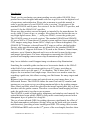
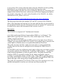
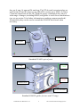
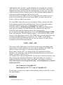
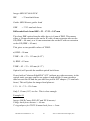
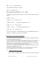
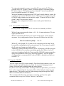
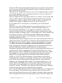
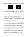
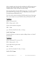
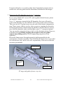
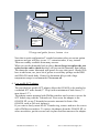
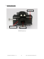
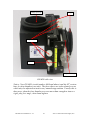
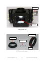
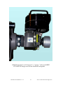
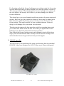
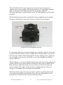
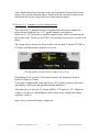
ONAG®
Patent Pending
Revision 5.1
ONAG® Standard, SC and XT*
ON Axis Guider
User Manual
Rev. 5.1 - 2011 © Innovations Foresight, LLC
http://www.innovationsforesight.com
* versions with guider drawtube and helical focusers
2011 © Innovations Foresight, LLC
http://www.innovationsforesight.com
Introduction
Thank you for purchasing our patent pending on-axis guider ONAG®. Ours
product have been designed and made with care to give its user the highest level
of experience and satisfaction. Please take a moment to read this manual in
order to get the most of your ONAG®, refer to section 7 for pictures of the
standard ONAG® and its parts. See section 9 for the ONAG® XT specifics, and
section 10 for the ONAG® SC specifics.
Please note this product was not designed, or intended by the manufacturer for
use by child 12 years of age, or younger. Also please do not look at the sun, or
any bright light sources, laser, …, with your ONAG, even at the guider port.
The ONAG® comes in several versions. The standard ONAG® and ONAG®
SC uses a M42 x 0.75mm thread (T-mount) system and have been optimized for
CCD imagers using large format APS-C chips (up to 28mm in diagonal). The
ONAG® SCT features a dovetail based X/Y stage as well as a helical guider
focuser, other specifications and uses are identical to the standard ONAG®.
The ONAG® XT supports full frame CCD, such as the 24mm x 36mm format,
and more, up to 50mm in diagonal and it uses a dovetail system for the scope
and imager optical ports. For more information concerning the ONAG®
products and imaging camera sensor chip illuminations please visit us at:
http://www.sbdcdev.com/ifi/support/onag-xt-ccdcmos-chip-illumination/
Searching for a suitable guide star has never been easier thanks to the ONAG
wide field of view and convenient quick set-up X/Y stage, providing an
exploration circle up to 46 mm (1.8”) in diameter. This is more than 1.3 arcdegrees for two meters focal length scope. Also there is no need to rotate for
searching a guide star, this allows reusing your flat frames for many targets and
nights.
Because it uses the same scope and optical train as your imager there is no
differential flexure. The ONAG® shares the same focal ratio (F-number) and
aperture as your scope set-up, providing maximum light to the guiding camera.
Since filters and filter wheels are placed in the imager optical path, they will not
interfere with the guider camera. Therefore even narrow band imaging will not
make the guide star(s) too dim to use anymore.
The ONAG® is made of high quality aluminum, and stainless steel material. Its
optical dichroic beam splitter (DBS) is fully multi-coated and protected with a
transparent layer of quartz for a long life.
The use of near infrared (NIR) for guiding decreases significantly the effect of
the Earth atmospheric turbulence (seeing) effect on the guide star (star wander
and distortion), providing a better tracking and SNR. The seeing effect in term
of FWHM and HFD scales as the 6/5th power of the wavelength, therefore there
ONAG® User Manual rev. 5.1
1
2011 © Innovations Foresight, LLC
is up to about 70% seeing reduction when using the ONAG® for auto-guiding,
depending of you scope aperture, local seeing, and exposure time.
Our patent pending real time auto-focus technology SharpLock (SL) keeps your
imager at best focus all the time, without any need of any imaging interruption
for periodic refocusing. SL works with all models of the ONAG®, for further
information on SL, please visit us at:
http://www.sbdcdev.com/ifi/education/real-time-auto-focus-sharplock/
This document describes the standard, SC and XT versions of the ONAG®.
Most of the functions and concepts are the same and therefore are presented for
the standard ONAG®. Specific information for the SC and the XT versions can
be found at the end of this document in the sections 9 and 10.
Description
The ONAG® is composed of 7 fundamental elements:
(1) A fully multicoated dichroic beam splitter (DBS), or “cold mirror”. The
DBS reflects typically more than 98% of the visible light, from 370nm to
750nm, toward your imager.
More than 90% of the near infrared (NIR) portion of the light, from 750nm to
1200nm, goes through the DBS to be used by your guiding camera. Because the
visible light is reflected, there is no optical aberration involved here.
The guide star may look like a tight cross since there is some astigmatism
coming from the fact that the starlight traveled through the DBS sets at 45
degrees.
Yet the DBS is only few millimeters thick and its effect does not impact popular
auto-guider software, like Maxim DL, GuideDog, PHD guiding…, or software
using centroid algorithms to track the guide star(s). The guide star half flux
diameter (HFD) is essentially similar for the imager and guider cameras,
resulting to a negligible change in SNR, if any. Using NIR for guiding reduces
the seeing effect which in turn provides tighter guide stars and better SNR, this
offsets also part of the energy drop coming from the use NIR.
The guide star astigmatism is a function of the scope focus position (in or out),
and this information is used by our real time auto-focus system SL.
ONAG® User Manual rev. 5.1
2
2011 © Innovations Foresight, LLC
ONAG® spectral response
Imager
to 750 nm
<
from 370nm
ONAG®
Scope
Guider
> 750 nm
ONAG® basic principle
(2) A scope port (SP). The SP allows the standard and SC ONAG® to be
attached to any scope using a standard T-threaded female connection (T-mount
M42 x 0.75), or a 59mm dovetail system for the XT version. We provides
standard offer, such as a 2” nosepiece, or a low profile female SCT adapter.
If you own an adaptive optic module, such as the Orion SteadyStarTM, or the
Starlight Xpress SXV, you can mount them directly between the SP and your
ONAG® User Manual rev. 5.1
3
2011 © Innovations Foresight, LLC
scope. Use the ONAG® for guiding and controlling the AO unit as well.
Since the off-axis ports of both products are not used they should be covered to
avoid parasitic light. We offer an adapter plate for the SBIG AO8 adaptive
optic module. This allows you to mount the AO8 in front of the ONAG®
(standard and SC versions).
Other adapter for any ONAG® can be made by preciseparts
(www.preciseparts.com), they have our products in file. The SBIG AO-L is
only supported by the ONAG® XT.
(3) An imager port (IP). The IP is used to attach the imager camera and related
accessories, such as a filter wheel, to the standard and SC ONAG® using a
standard male T-thread (M42 x 0.75mm), or a 59mm dovetail system for the XT
version.
(4) A guider port (GP). The GP is used to attach the guider camera to the
ONAG®, any version, using a male T-thread (M42 x 0.75mm). A low profile
T-threaded ring is provided to secure the camera at the desired position.
The GP is also the guider focuser drawtube (see the element 5 below).
(5) A guider focuser (GF). The GF provides up to 9 mm of travel to adjust the
guider focus. The focuser uses a heavy duty compressing ring to insure a 360
degrees grip on the drawtube. This design eliminates any flexure. Since the
drawtube is 1¼” in diameter and can be removed, this allows the use of any
standard 1¼” accessories. Very handy if your guide camera nosepiece does not
come off. In such configuration you may need an extra 1¼” extension tube to
reach focus (see section 7). The ONAG® SC features a new helical focuser, see
section 10 for further information.
(6) A X/Y stage (XYS). The XYS allows easy and quick search for a suitable
guide star. It is attached to the ONAG® body on one end, while it supports the
guider focuser on the other end. The XYS slides in both directions (X, Y axis)
using two stainless steel shafts; each axis can be secured with 4 nylon screws
(two screws and two thumbscrews) when you have settled on your guide star.
For convenience the screws can be tightened to provide any level of friction and
comfort, while moving the stage. In normal operation only the two nylon
thumbscrews for each axis need to be touched. The other 2 slotted nylon screws
are tighten only once using a screwdriver to insure proper smooth motion and
remove any play. Do not over tighten them.
(7) A collection of T-threaded (M42 x 0.75) extension tubes are available from
Innovations Foresight. They can be used with any of the standard and SC
ONAG® optical ports (SP, IP, and GP), or at the ONAG® XT GP.
There are also three dovetail extension tubes available for the ONAG® XT,
ONAG® User Manual rev. 5.1
4
2011 © Innovations Foresight, LLC
they are 8 mm, 16 mm and 24 mm long. The XT dovetail extension tubes are
used for the SP and IP, however any ONAG® versions use a M42 x 0.75mm
(T-mount) connection for the GP. With the proper combination they allow a
wide range of imager (including DSLR) and guider to reach focus simultaneous
(see set-up section 3 for further information on making cameras parafocal).
Alternatively they can be used to extend the ONAG® back focus when
necessary.
Imager port
Guider port
Scope port
Standard ONAG® optical ports
Y axis
(+ sense)
X/Y stage
X axis
(+ sense)
Focuser screw
Focuser drawtube
Standard ONAG® guider focuser and X/Y stage
ONAG® User Manual rev. 5.1
5
2011 © Innovations Foresight, LLC
1. Set-up
For proper operation it is required that cameras, imager and guider, reach
focus simultaneously (be parafocal). T-threaded extension tubes (spacers)
or/and dovetail spacers for the ONAG® XT are used to conveniently spaced,
when needed, the cameras from the ONAG® body.
There are two low profile T-rings for rotating and locking the cameras to the
desired positions. Alternatively the ONAG® XT dovetail system offers a
total freedom of rotation for the IP and SP.
Since the IP and GP male T-threads are longer than the extension tube
threads, it is recommended to use the T-rings at those ports. Although they
could be used with extension tubes as well, you may run out of thread length
to safely secure the cameras.
The ONAG® is connected to your scope using the SP. It is highly
recommended to use a rigid assembly, such as the T-thread, the SCT adapter,
or a 2" adapter with a compression ring on the scope side. Alternatively you
can get custom adapters (for any ONAG®) from our partner preciseparts
(www.preciseparts.com). Innovations foresight offers also 2” nosepiece and
SCT adapters for every ONAG® version.
The ONAG® DBS has been laser aligned with care and precision for
providing the best results, however an inappropriate user set up could impact
significantly the image quality.
Thumb screen set ups may result on poor optical alignment leading to tilt of
the camera focal plane and distorted star across the image. Therefore they
are not encouraged, we recommend using rigid connection, such as threads
and compressing rings.
It is not recommend that user touch any of the ONAG® mirror adjustment
mechanism, our product have been aligned at factory, therefore please do not
try to do so, you will upset the factory adjustment and you may void the
warranty.
ONAG® User Manual rev. 5.1
6
2011 © Innovations Foresight, LLC
1.1. Differential back focus
The standard and SC ONAG® have 66 mm (2.6”) of optical back focus from
the SP (front plate) to the IP (T-thread), and 92 mm (3.62”) from the SP to
the GP, when the GF drawtube is half way extended.
The ONAG® XT has an IP backfocus of 68mm and the same GP back focus
of 92mm with the GP drawtube half way extended and the GP astigmatism
corrector in place.
This document and following examples assume a standard (or SC) ONAG®,
for the XT versions just subtract 2mm with a drawtube focuser, and 5mm
with a helical focuser, from your guiding camera back focus (GBF) for
reusing the following table and calculations. There is 26 mm (1.02”)
difference on back focus between the IP and GP, associated with spacers (Tmount), such as the 8mm and 16mm long ones available by Innovations
Foresight, this allows for a wide range of imager and guider pairs, including
DSLR. Innovations Foresights also provides dovetail extensions tubes (8mm,
16mm, 24mm long spacers) for the SP and IP of the ONAG© XT.
The key factor here is the differential back focus (DBF), which is defined
as the difference between the imager back focus (IBF) and guider back
focus (GBF):
DBF = IBF – GBF
Most of the time this number is greater than zero, but in some configurations
it could be negative.
Of course both back focus values must include any related accessories
mounted in series with either camera, such as a filter wheel. Should you have
a focal reducer FR, see sections 5 and 6 below.
The table below provides for convenience the recommended selection of
extension tube (spacers of 8mm and 16mm long) for a correct set-up. For
instance the combination of 8mm + 16mm spacers can be replaced by a
24mm spacer. All you need is your imager (including the filter wheel, if any)
and guider optical back focus values, see your product specification, or
contact the relevant manufacturer or reseller. With those two numbers,
compute the DBF, and refer to the table.
The table here provides solutions with 8mm and 16mm spacers only.
However if you have your own spacers, or want to use third party spacers,
you can reuse this information to find the best match, just sum the
recommended spacer lengths from the table to get the total spacer length
required. Alternatively you can also use the relations below to compute the
necessary extension value at the guider port (GP). Positive values mean the
guider must be moved away from the ONAG®, negative values the imager
must be moved away from the ONAG®.
ONAG® User Manual rev. 5.1
7
2011 © Innovations Foresight, LLC
ONAG® Standard and SC extension value = DBF + IXT - 26 (in mm)
ONAG® XT extension value (drawtube focuser) = DBF + IXT - 24 (in mm)
ONAG® XT extension value (helical focuser) = DBF + IXT - 21 (in mm)
Where IXT is the length of the imager extension tube (spacer) used (in mm),
if any. This spacer is placed between the ONAG® IP and the imager (or
filter wheel). IXT values lower than 16mm will reduce the upper Y axis
travel of the XYS leading to a low profile configuration (see 3.2.2).
This equation assumes, like the table, that the guider focuser drawtube is
extended half way (~4.5mm).
DBF
[mm]
-24
-16
-8
0
8
8
16
16
16
24
24
32
32
32
40
40
40
48
48
56
56
64
72
IP
Extension
Tube(s)
[mm]
2x16 + 2x8
2x16+8
16 + 2x8
16+8
16+8
16
16+8
16
8
16+8
None
16
8
None
16
8
None
8
None
8
None
None
None
GP
Extension
Tube(s)
[mm]
None
None
None
None
8
None
16
8
None
8+16
None
16+8
16
8
16+2x8
16+8
16
16+2x8
16+8
2x16+8
16+2x8
2x16+8
2x16 +2x8
IP
Back Focus
(IPBF)
[mm]
114
106
98
90
90
82
90
82
74
90
66
82
74
66
82
74
66
74
66
74
66
66
66
Comment
DBF < 0
DBF < 0
DBF < 0
Low profile
Low profile
Low profile
Low profile
Low profile
Low profile
Low profile
Low profile
Low profile
Low profile
Low profile
Low profile
Recommended extension tube v.s. differential back focus (DBF)
ONAG® User Manual rev. 5.1
8
2011 © Innovations Foresight, LLC
Although the table provides a good indication for selecting the extension
tubes, it is only a recommendation. Actual device back focus values from
manufactures may deviate from their specification, or may vary over time
without warning. Other elements, such as filter thickness and mechanical
connections could impact the final set-up as well.
Since most likely your DBF will not be in the table, the normal course of
action is to look in the table for the closest DBF, yet some time the one
below, or above could be necessary.
For some DBF values there are several options. Either of them will allow
both cameras to reach focus simultaneously, however some may require
using the ONAG® low profile configuration (see section 3.2).
They also differ on IP back focuses (IPBF). The IPBF is defined has the
back focus, or distance, (in mm) between the ONAG® IP (top of the
ONAG® body) and the imaging camera chip (image plane).
For an optical train and scope point of view, the total optical back (TOBF)
focus, including the ONAG® and the imager + its accessories (filter wheel,
if any), is the right figure of merit. The TOBF will eventually limit the scope
focusing mechanism ability to reach focus. The TOBF, not including
accessories before the ONAG® such as a focuser and/or AO unit, can be
estimated with the following formula:
TOBF = IPBF + IBF
The choice of the right option is a function of the scope performance and
requirement. In some situations one may want to minimize the TOBF, but
there are many cases where we may need a larger back focus.
Most scopes, such as SCT, are designed for some optimal back focus
distances, for which they reach their nominal specifications (such as focal
length, F number, field of view).
For instance the Celestron EdgeHD SCT series have a built-in corrector, and
they will provide optimal performance if the focal plane is at, or near, a
predefined distance from the scope visual back. According to Celestron
(http://www.celestron.com/c3/support3/index.php?_m=knowledgebase&_a=viewarticl
e&kbarticleid=2260):
133.35 mm for 8” EdgeHD SCT
146.00 mm for 9.24”, 11”, and 14” EdgeHD SCT
In such case you may even want to add extension tube(s) on the SP to reach
the right distance.
Example #1:
ONAG® User Manual rev. 5.1
9
2011 © Innovations Foresight, LLC
Imager SBIG ST-4000 XCM
IBF
= 23 mm back focus
Guider SBIG Remote guider head
GBF
= 17.53 mm back focus
Differential back focus DBF = 23 – 17.53 = 5.47 mm
The closet DBF option from the table above is 8 mm of DBF. This means
either, a 24 mm extension tube on the IP with a 8 mm extension tube on the
GP (IPBF = 90 mm), or a 16 mm extension tube on the IP with no extension
on the GP (IPBF = 82 mm).
This gives us two possible values of TOBF:
a) IPBF = 90 mm
TOBF = 90 + 23 = 113 mm (4.45”)
b) IPBF = 82 mm
TOBF = 82 + 23 = 105 mm (4.13”)
Option b) will provide the smallest optical back focus.
If used with a Celestron EdgeHD 8” SCT (without any other accessory in the
optical train) you may want to use option a) and add the 16 mm extension
tube between the SP and the provided low profile SCT adapter (7.5 mm back
focus). This will place the imager focal plane at:
113 + 16 + 7.5 = 136.5 mm
Only 3.15 mm (1/8”) too far . This is close enough.
Example #2:
Imager DSLR Canon EOS (EF and EF-S mounts)
Flange back focus distance = 44 mm
T-ring adapter for EF/EF-S mount back focus = 8 mm
ONAG® User Manual rev. 5.1
10
2011 © Innovations Foresight, LLC
IBF = 44 + 8 = 52 mm back focus
Guider ORION StarShoot autoguider
GBF = 15 mm back focus
Differential back focus DBF = 52 – 15 = 37 mm
The DBF closest option from the table is 40 mm. The three possible options
lead to:
a) IPBF = 82 mm
TOBF = 82 + 52 = 134 mm (5.28”)
b) IPBF = 74 mm
low profile configuration, see 3.2
TOBF = 74 + 52 = 126 mm (4.96”)
c) IPBF = 66 mm
low profile configuration, see 3.2
TOBF = 66 + 52 = 118 mm (4.65”)
Be aware that option c) could prohibit access to some DSLR functions and
interface, if its body is too close to the ONAG®.
1.2. Standard versus low profile configuration
The ONAG® has three effective degrees of freedom for exploring the field
of view in search for a guide star.
The X/Y stage (XYS) provides two orthogonal axis X and Y (see section 2),
while the rotation of the ONAG® body adds a third degree for freedom.
This gives an overall exploration circle up to 46 mm in diameter and allows
the ONAG® to be used in different and flexible ways.
There are two fundamental configurations, standard and low profile, which
can be used to optimize the set-up.
While the X stage axis can always be used at full range, there are may be
travel limitations for the Y axis, please see the section below.
1.2.1. Standard profile configuration
In the standard configuration the XYS can be fully extended in the upper
ONAG® User Manual rev. 5.1
11
2011 © Innovations Foresight, LLC
Y axis portion (positive sense, toward the IP, see section 2). This is
possible only if a 16 mm, or more, extension tube(s) is attached on the
IP. Otherwise the XYS will experience limited Y travel toward the IP
(see low profile section 3.2.2 below).
With the standard configuration the XYS can be used alone to search for
a guide star across the full field of view. When used in conjunction with
ONAG® body rotation you can achieve up to 23 mm of off-axis offset
(both X and Y axis at travel ends)!
However this configuration leads to more total optical back focus
(TOBF).
1.2.2. Low profile configuration
In low profile configuration the Y axis travel is limited, as follow:
With a 8 mm extension tube there is 16 – 8 = 8 mm reduction of Y axis
upper portion travel.
With no extension tube there is no travel on the upper Y axis portion
anymore. Any configuration below 16 mm will restrict the travel by:
Travel restriction [mm] = 16 – X
Where X is the length (X<16 mm) of the extension used in mm. In the
low profile configuration the lower portion of the Y axis travel, and all
the X axis travel range, are fully usable.
Therefore a rotation of the ONAG® up to 180 degrees will allow access
to the full field of view when searching a guide star. What is left of Y
axis travel combined with the X axis and the ONAG® rotation provides
again an exploration circle up to 46 mm in diameter. The low profile
configuration is recommended if a short TOBF is desired (see table on
section 3.1).
2. Using the ONAG®
The use of the ONAG® is quite simple. First focus both cameras, next you
select a guide star and then you are ready for a normal imaging session
using your usual auto-guiding hardware and software.
If you are not using an automatic tracking calibration procedure, you do not
have to be concerned by the inversion effect of the dichroic mirror in your
manual entry. The guider uses the light coming straight through the DBS,
there is no reflection involved here.
The recommended focusing procedure, assuming you have the right
extension tube set-up, see section 3 above, is as follow:
ONAG® User Manual rev. 5.1
12
2011 © Innovations Foresight, LLC
Center the XYS and gently tight the nylon screws to insure an easy slide of
any axis in any direction when displaced by hand, while the stage does not
move under its own weight.
Tighten the GF stainless steel focuser screw just enough allowing a smooth
travel of the drawtube with a minimum of play (see section 10 below for
the ONAG® SC helical focuser).
Select a bright star near your target (do not over expose), or the zenith, and
center it on the imager. Then focus the imager using the scope focusing
mechanism, as usual. Using the XYS, center the same star and focus it
using the GF, tighten, by hand, the GF screw (never use a tool.)
If you cannot do so you may have to reconsider your extension tube
selection.
When you move the ONAG® guider focuser drawtube all the way, the
guide star should change form from a vertical ellipsoidal shape to a
horizontal ellipsoidal shape, or the opposite in function of your CCD
reference frame position. The optimal focus point is achieved when both
ellipsoid collapse becoming a spot, or a little tight cross. This is normal and
not a source of concern. This feature becomes handy when manually
seeking for best focus and it is used indeed by our real time autofocus
technology SharpLock (SL).
The ONAG® XT has an integrated corrective optics and therefore does not
exhibit such effect, the guide star is round and seeing limited. However the
XT guider drawtube can be rotated to create some astigmatism for using
SL. This corrector is not available with the helical focuser versions.
Since most scopes and optical components are not optimized for the near
infrared (NIR) there is maybe small distortion involved anyway.
Autoguider algorithms are mainly based on centroid algorithms and are not
sensitive to this. They average pixels from the all guide star area, so the
maximum pixel value or FWHM are not much relevant in this case, unlike
for imaging. If you use computer assisted focusing software, such has
Maxim DL, the right figure of merit should be the half flux diameter
(HFD), or ½ FD. The half-flux diameter is the diameter in pixels that
contains half the energy in a star image. In other words, if you add up the
pixel values (less the background) inside the diameter, and outside the
diameter, you will get the same number. This measurement gives a very
similar answer to FWHM, but it is much more robust in the presence of
seeing, noise, and can handle non circular distorted images, even out-offocus like "donuts". The HFD varies linearly with focus position making it
reliable to locate the best focus regardless the star shape.
If you use the PHD guiding software watch the SNR value, you should seek
for its maximum. If you do not use any software, the best focus will be
achieved when the guide star cross like shape is minimized and symmetric.
The two images below show the same guide star seen from the imager (IP)
ONAG® User Manual rev. 5.1
13
2011 © Innovations Foresight, LLC
on the left or from the guider (GP) on the right at best focus, same camera,
set-up, and cropping.
Guide star seen from IP
Guide star seen from GP
HFD=6.0px, FWHM=3.4px HFD=6.2px, FWHM=5.2px
The cross like shape of the guide star viewed from the GP is clearly visible.
Yet as far as the energy budget is concerned both cases have almost the
same HFD. The GP larger FWHM is due to the star non-circular shape.
During this focusing process avoid to over exposing the guide star. Doing
so will bias the HFD values, and make the star shape more difficult to guess
for accurate focus.
Bright over expose stars may result in ghost images offset by few
millimeters (hundreds of pixels). Those are reflections from the DBS and
nearby surfaces, such as the CCD/camera windows. Most optic are not
coated for NIR. The reflections are out of focus and will look like faint stars
with "donuts" like shapes. This is not issue.
When you reached the desired focus, hand tight the ONAG® focuser screw
(stainless steel) to avoid any motion or flexure.
Now you are ready to come back to your target. Center and fine focus it on
the imager. Then it is time to locate and center your guide star on the guider
camera using the XYS. If necessary adjust the guider focus with the GF.
Now tighten by hand all 4 nylon thumbscrews to avoid any flexure (never
use a tool.)
Proceed with your imaging session.
Should you keep your cameras attached to the ONAG® for the next
session, there is no need to focus the guider again (if you did not touch the
GF).
You will just need to focus the imager and use the XYS to locate the guide
star, which will be automatically on focus, saving time.
Although if the DBS has a high efficiency broad band antireflection (AR)
coating on its back, if you overexpose bright star(s) you may experience
dimmed ghost images of them offset by few hundred pixels, unless your
imager has a near infrared (NIR) cutting filter.
Most, if not all, one-shot color cameras and DSLR have UV + NIR
ONAG® User Manual rev. 5.1
14
2011 © Innovations Foresight, LLC
blocking filters. Monochrome ones usually do not, however the associated
filters, such as LRGB should take care of this, cutting the NIR, typically
above 700 nm.
If not you may have to consider adding a UV-NIR filter in front of the
imager. Alternatively should you want to image in NIR, avoid
overexposing your target. For scientific and research purpose a ghost image
may not be much an issue since it is dimmed and offset from its source by
about 3 mm.
In any case never place any NIR filter, or any other filters blocking the
NIR, in front of the ONAG®, otherwise you will not have any image of
any star on your guider camera!
3. Focal reducers
Focal reducers FR can be used with the ONAG®. Those reducers should be
located at a specific distance DFR from the imager focal plane, please refer
to your reducer specification and user manual. There are two options
available:
You can place the FR in front of the ONAG®, at the SP, if your TOBF
associated with your set-up matched the FR required back focus.
Most popular 0.63x focal reducer/correctors (such as Meade or Celestron)
can be used in a range of +/-1" (+/- 25mm) to their nominal DFR values
without any significant alternation of their correction performances.
However the actual reduction factor h is a function of the distance q from
the focuser to the imager focal plane.
If q is different from its nominal DFR value, so h. In first approximation we
have:
h=1-q/f and q=f (1-h)
Where f is the reducer effective focal length.
For instance the Celestron 0.63x corrector/reducer has a focal of 235mm,
therefore its nominal DFR value is:
DFR0.63x=235 (1-0.63)=87mm, or 3.42”
If placed one inch further away from the imager focal plane its reduction
factor h+1" becomes:
q+1"=DFR0.63x+25.4=112.4mm
ONAG® User Manual rev. 5.1
15
2011 © Innovations Foresight, LLC
h+1"=1-112.4/235=0.52x instead of 0.63x, a 17% decrease.
FR in front of ONAG® example #1:
Reducer Starizona SCT corrector 0.75x
DFR = 90mm
Imager SBIG ST-8300C
IBF = 17.5mm
ONAG® in low profile mode
Back focus = 66m.
You will need an extension tube of 90-66-17.5=6.5mm to meet the
Starizona DFR value of 90mm.
FR in front of ONAG® example #2:
Reducer Celestron 0.63x (f=235mm)
DFR = 87mm
Imager QSI-683ws
IBF = 35.5mm (1.4")
ONAG® in low profile mode
Back focus = 66mm
q=66+35.5=101.5mm leading to a reduction factor:
h=1-101.5/235=0.57x 9% larger.
The second option is to place the FR at the ONAG® IP, before the imager.
In this case the ONAG® back focus does not play any role anymore. We
are here in the classical situation.
However you will have to find the right spacing for reaching focus with
your guider by trial and error, since the table from section 3.1 above will
ONAG® User Manual rev. 5.1
16
2011 © Innovations Foresight, LLC
not be correct anymore. Most likely you will need to use extra extension
tubes to move the guider further away from the ONAG® body.
The following relation is useful to guide you through this process:
p=q/h
Assuming you are in focus at the imager focal plane with the FR in place
then p is the distance from the FR to the scope focal plane. This is the
distance where you would be in-focus if the FR is removed and the scope
focus is left untouched. In short with a FR you have to focus your scope at a
plane behind the FR located at the distance p from the FR. This is also the
distance you need to consider for the guider, since in this configuration FR
is not part of its optical path. For instance with a Celestron 0.63x focal
reducer (f=235mm, DFR=87mm) p should be:
p=87/0.63=138mm
It is worth to mention that the calculation of the effective focal reduction
factor h is more complex with a SCT since those scopes require moving the
principal mirror forward, which in return changes the scope effective focal
length f.
For most SCT the focal length increases roughly 3 to 4 times faster than the
back focus. Let's use an average value of 3.5 times.
The nominal SCT focal length fnominal is reached around 100mm (4") of
back focus (from the visual back). This allows for a star diagonal and eye
piece room.
For instance with a C11 at f/10 we have fnominal=2800mm. Therefore if we
use a Celestron 0.63x FR in front of the ONAG®, in low profile mode, the
effective focal f becomes:
p=138mm
ONAG® back focus=66mm
f0.63x = 2800+3.5 (138+66-100)=3164mm
And the resulting effective reduction factor h is:
h=0.63 (3164/2800)=0.71x
ONAG® User Manual rev. 5.1
17
2011 © Innovations Foresight, LLC
About 13% larger which means a reduced focal length of 1993mm instead
of 1764mm. You effectively use this C11 at f/7.1.
The Celestron FR 0.63x, or other ones for that matter, will still correct for
the SCT field curvature as before, with a slight change in h.
In short the FR does reduce the SCT focal length f and does retain any of its
optical correction capability, when applicable. However due to the FR back
focus f is larger than fnominal leading to a larger reduction factor h relative to
fnominal.
ONAG® User Manual rev. 5.1
18
2011 © Innovations Foresight, LLC
4. Adjustable focal reducer AFR
In order to minimize the resulting guider optical path associated with a FR
in front of the imager (ONAG® IP) IF offers an adjustable FR (AFR) for
your guider.
The AFR works with almost any FRs as well as most guiders. It has been
optimized for NIR imaging using fully multi-coated aspheric optics.
AFR adjustable FR for NIR
The normal procedure with the AFR will be to place your imager FR
directly at the ONAG® IP. You may need adaptors for your FR to interface
with the ONAG® T-thread IP.
Focusing ring
From
ONAG®
To guider
X
Locking screw
AFR parts and nomenclature
ONAG® User Manual rev. 5.1
19
2011 © Innovations Foresight, LLC
Then place the AFR at the ONAG® GP in one end and connect with your
guider in the other end.
Now position the ONAG® guider focuser half way out (about 4mm), this
will give you some room for fine focus later.
Search for a bright star, but do not over expose, and place it at the center of
the imager, carefully focus your scope. Center the ONAG® X/Y stage
(zeros on the yellow rulers).
For the next step you need to estimate the AFR extension value X (see the
AFR parts and nomenclature figure above). The required X value is given
by the following relation:
X=qAFR-GBF
With GBF your guider back focus and
qAFR =q/h (102/(q/h+102))
the required AFR back focus.
Where q (in mm) and h are your imager FR back focus, most likely q=DFR,
and its reduction factor respectively. See your FR specifications and user
manual for those values. By the way the above SCT comment does not
apply here.
By adding, when necessary, one or more ONAG® T-threaded extension
tubes (8, 16, 24mm) you have access to a large range of AFR extension
value X listed in the table below:
X
Minimum
[mm]
26
34
42
50
58
66
74
X
Maximum
[mm]
36
44
52
60
68
76
84
Extension
Tube(s)
[mm]
None
8
16
24
24+8
24+16
24+16+8
AFR extension value ranges v.s. extension tubes
ONAG® User Manual rev. 5.1
20
2011 © Innovations Foresight, LLC
Select a suitable range from the table and adjust the AFR focusing ring to
bring the AFR extension length close to the selected X value with the
extension tube(s), if any. You can use a ruler to help.
Now focus the guider using the AFR focusing ring, you may have to adjust
the ONAG® X/Y stage to center the star. When done, secure the AFR
focusing ring associated plastic screw.
Fine focus can be achieved with the ONAG® guider focuser if necessary.
Now you are ready to use your ONAG® with your FR and the IF AFR.
Example #1:
Reducer Celestron 0.63x
DFR = 87mm and h = 0.63x
Guider Orion StarShoot autoguider
GBF = 15mm
qAFR =87/0.63 (102/(87/0.63+102)) = 58.7mm
X=58.7-15=43.7mm
From the table above we have two options, adding a 8mm, or a 16mm Tthreaded tube.
Example #2:
Reducer Starizona SCT corrector 0.75x
DFR = 90mm and h = 0.75x
Guider SBIG Remote guider head
GBF = 17.5mm
qAFR =90/0.75 (102/(90/0.75+102)) = 55.1mm
X=55.1-17.5=37.6mm
ONAG® User Manual rev. 5.1
21
2011 © Innovations Foresight, LLC
From the table above we need to add a 8mm T-threaded extension tube to
reach focus with our guider and the Starizona FR attached to the imager.
5. Removing the GF drawtube, use of a 1¼” nosepiece
If you own a ONAG (SC or new XT) with a guider helical focuser, please
see section 11 below.
Use a 1¼” nosepiece instead of the GF drawtube, first you will need to
remove the drawtube. For the ONAG© SCT refers to the section 10 below.
There are two #6-32 nylon screws on each side of the focuser compression
ring. Those screws slide in two key slots, or groves, stopping the drawtube
for leaving the focuser compression ring. Remove and save the two screws,
now slide the drawtube away, and then place your 1¼” nosepiece instead.
You can use the compression ring to lock it at the desired position. However,
remember there is nothing stopping the nosepiece and your guider
camera from falling anymore if the compressing ring screw is not
tightened!
Be careful, Innovations Foresight cannot be held responsible for the
consequence of such an accident. This ONAG® GF mode of use is provided
for convenience only, and it is the sole responsibility of the user to take the
necessary precautions.
Focuser drawtube
Focuser ring
#6-32
threaded hole
for nylon
screw
Focuser screw
XY stage and guider focuser, top view
ONAG® User Manual rev. 5.1
22
2011 © Innovations Foresight, LLC
Focuser screw
Focuser drawtube
Focuser ring
#6-32
threaded hole
for nylon
screw
XY stage and guider focuser, bottom view
Note that in such configuration T-treaded extension tubes are not an option
anymore and you will have to use 1¼” extension tubes, if any, instead.
Those are readily available from many sources.
When you put the drawtube back in place, do not forget to replace the two
nylon screws and to check that they will prevent the drawtube from falling.
The drawtube comes lubricated with grease for easy tube travel. Should You
have to add some, use just a bit of grease to avoid any spillage on the DBS
and ONAG® inside body. Grease for aluminum alloys with a large
temperature range is recommended. Never use oil.
6. Low profile SCT adapter
The provided low profile SCT adapter allows the ONAG® to be attached to
a standard SCT male thread (2” 24 tpi) with a minimum of back focus (7.5
mm, about 1/3”).
The adapter comes mounted with Phillips stainless steel screws to secure the
SCT female ring with the T-thread core. First screw the adapter to the
ONAG® SP, or any T-threaded accessories mounted in front of the
ONAG®, such as AO unit, tighten it.
If you want to freely rotate the SCT female ring, remove and save the screws
with a Phillips screwdriver. To remove the adapter from the ONAG® SP, or
other accessories, put the screws back in place and then unscrew the adapter.
ONAG® User Manual rev. 5.1
23
2011 © Innovations Foresight, LLC
7. ONAG® and its parts
X/Y stage (XYS)
Guider focuser (GF)
Guider port (GP)
ONAG® back view
ONAG® User Manual rev. 5.1
24
2011 © Innovations Foresight, LLC
Imager port (IP)
T rings
Stage screws
Y ruler
Compression ring
ONAG® side view
Notice: New ONAG® (serial number 4000 and above) and the XT version
have 4 nylon thumbscrews only). The four others are nylon slotted screws
which may be adjusted to insure easy smooth stage motion. Usually this is
done once, than the four thumbscrews are more than enough to insure a
rigid, play free stage, when hand tighten.
ONAG® User Manual rev. 5.1
25
2011 © Innovations Foresight, LLC
Focuser screw
Scope port (SP)
ONAG® front view
SCT adapter ring
SCT adapter core
SCT adapter screws
Screw hole
SCT lower profile adapter
ONAG® User Manual rev. 5.1
26
2011 © Innovations Foresight, LLC
ONAG® mounted on Celestron 8” (“orange” tube) with SBIG
ST2000XCM imager and Orion StarShoot autoguide
ONAG® User Manual rev. 5.1
27
2011 © Innovations Foresight, LLC
8. ONAG® and tracking software, some considerations
Although the ONAG® solves differential flexure problems while featuring a
wide field of view to locate a suitable guide star, the tracking software is also
a key element in the all process of auto-guiding.
It is paramount to understand its basic operation and choose the right
software settings to achieve good image quality.
There are many tracking software available, such as Maxim DL, PHD
guiding, GuideDog to name few. They typically use centroid algorithms
averaging pixel values all around the guide star area to estimate its position
with sub-pixel accuracy. The guide star shape does not matter much, as long
as it is not clip, consistent across frames and is not too much spread or fain.
For that matter the little cross shape of the guide star seen from the ONAG®
GP in NIR does not impact the software tracking capability.
Guiding with the ONAG® means using the same focal length than imaging,
and unlike guide scopes, this translates most of the time to a small field of
view, especially for long focal scopes. Meaning for each guide star frame we
may expect having more seeing effect and other short term perturbation
contributions. Therefore most of the time it is recommended to bin the
guider image by 2x or 3x, which will average nearby pixels, unless the
guider pixel size is much great than the imager one, 4x or above.
This can be seen as a low pass filter operation, limiting seeing and chasing
the noise like guide star motion at each frame.
Yet the most important single parameter of any tracking software is the
aggressiveness, which is the level of correction the algorithm will apply to
the mount after each new guide star frame. In control system theory (close
loop systems) this is known as the feedback gain Gf.
If it is too low the correction is not enough to compensate for the mount
drift. In the other hand if Gf is too large the correction will become instable
and erratic. The later is the most problematic and common issue in tracking
leading to elongated star in the images even with near perfection optics.
From the above considerations we recommend you start with a low
aggressiveness (1/2 or 50%, or less) to begin with, and increase it slowly
only if you have to. For instance for Maxim DL this means 5, in PHD
guiding this would translate to 50, for both cases it is half way to full scale
correction (1, or 100%), or less.
A common figure of merit for the tracking error quality evaluation is the rms
(root mean square) error value over a time window. However even with a
low error value you still may experience elongated stars.
Very often bright stars are much brighter than the target under consideration
for your imaging session, such as galaxy, or nebulas.
During several minute of exposure a short extreme erratic tracking correction
during a second or so way above the rms value will be enough to distort the
ONAG® User Manual rev. 5.1
28
2011 © Innovations Foresight, LLC
bright stars. Those outliers are more likely if Gf is large. They may also
come from some mechanical problems, such as over compensated backlash
by the mount software.
If your mount is equipped with a periodic error correction (PEC) you should
use it. We also recommend unbalancing just a little your mount in AR,
making it "East heavy" to avoid any backlash on the RA axis. Be aware this
must be done differently for both meridians on equatorial mounts.
Backlash compensation done by most mount software may result, if too
large, in bumping the mount, especially on DEC axis (equatorial mounts) for
which the drive motor can reversed it direction. Yet too little backlash
compensation leads to lag in the correction and erratic tracking. If you have
difficulties to solve this DEC problem you can use a simple technique:
Just disturb a little bit the mount polar alignment, this will result in a single
direction DEC drift, the DEC drive motor does not need to reverse anymore
avoiding backlash issues.
Most software allows disabling either correction direction in AR and DEC,
use this feature when available. You need just a very little polar alignment
error to accomplish this trick.
Do not misalign your mount too much otherwise long exposures may exhibit
field rotation.
If this is your first experience with guiding at the same focus than imaging,
you will need some time to find the right settings most likely, but the reward
will be huge in term of image quality. Should you need more support or
advise please feel free to contact us we will be glad to help.
ONAG® User Manual rev. 5.1
29
2011 © Innovations Foresight, LLC
9. ONAG® XT specific
This section describes the ONAG® XT specific features and procedures.
Please read the above sections carefully first. There are two version of the
ONAG XT, one with a drawtube focuser, the other (new) with a helical
focuser, see at the end of this chapter about how to use this helical focuser.
Below, on the left an image of the ONAG® XT with a drawtube focuser, on
the right the ONAG XT with a helical focuser.
ONAG® XT with drawtube focuser
ONAG XT with helical focuser
Innovations Foresight offers M42 x 0.75mm (T-mount) spacers (8mm and
16mm long) and male/female dovetail (59mm) spacers 8mm, 16mm, and
24mm long. There are also female and male adapters for 2" and STC
connections, the 2" female adapter has a stainless steel thumbscrew for the
compression ring (full body). Although the compressing ring provides a very
rigid connection accident may happen and it is a good practice to have this
back system to lock in place your equipment.
This female adapter has a 30mm depth which is more than enough for most
nosepieces. Be carefully not to exceed this length otherwise you may touch
and damage the dichotic mirror. Innovations Foresight would not be
responsible for product (any ONAG® and associated accessories) and
equipment damages due to failure to follow proper procedures,
recommended care, and good practice.
The ONAG® XT uses a 59mm dovetail system for the IP and SP. This
insures a rigid, squared, and secure connection, as well as provides minimum
back focus solutions. Each female dovetail is equipped with three #4-40
UNC stainless steel set screws.
They must all be tightening to insure a secure attachment using a 0.05"
Allen (hex-key) wrench (one is provided with the ONAG® XT). The set
ONAG® User Manual rev. 5.1
30
2011 © Innovations Foresight, LLC
screw tips have an oval shape to insure a good grip and to protect the
aluminum surface of the male dovetail part. Only limited force is needed to
lock in position the dovetails, please do not over tighten the set screws. We
do recommend that you use the long side of the Allen wrench, as shown in
the image below, resist using the short side which may lead to excessive
torque.
Allen wrench recommended procedure to use with the dovetail set screws
The two images below show the location of the set screws on the ONAG®
XT body. Accessing the third dovetail IP set screw requires moving down
the X/Y stage toward the negative direction of its Y axis.
ONAG® User Manual rev. 5.1
31
2011 © Innovations Foresight, LLC
Three set screws (#4-40), please tighten all
Three set screws (#4-40), please tighten all
ONAG® XT IP set screw locations
ONAG® XT SP set screw locations
The new ONAG XT is equipped, as the ONAG SC, of a guider helical
focuser at the GP.
The image below shows the ONAG XT helical focuser.
ONAG XT guider helical focuser
The helical focuser provides a smooth fine focus capability for the guider.
Each turn (360 degrees) move the focuser by 400 microns (0.4mm).
ONAG® User Manual rev. 5.1
32
2011 © Innovations Foresight, LLC
For focusing, unlock the focuser locking screw, and just rotate the focus ring
in either directions until you have reached focus with the guider, one turn is
400 microns (0.4mm). Then hand tight the focuser locking screw, please do
not over tight it, nor use any tool to do so, you may damage your helical
focuser otherwise.
This should give you a good enough rigid focus position for most setups and
guiders. However you can continue to rotate the focus ring (by hand) in the
same direction, while the focuser screw is lock, to secure even more the
focus position. This maybe useful for heavy guiding cameras. However
doing so will change a bit your initial focus position.
Therefore in this context the best procedure calls for recording how much
you could rotate further from the best focus after you tighten the focuser
locking screw, then back off to the best focus position.
Now unlock the focuser locking screw, and continue to back off the focus
ring by the recorded amount above. Finlay lock the focuser locking screw
and rotate the focuser ring to the best focus position again.
10. ONAG® specifics
The ONAG® SC has pestilential the same specifications than the standard
ONAG®. It has been designed for ASP-C chips, up to 28mm in diagonal.
ONAG® SC unit
ONAG® User Manual rev. 5.1
33
2011 © Innovations Foresight, LLC
The ONAG® SC X/Y stage is based on a dovetail system, there is no
stainless steel shaft anymore. This design insures a very rigid and compact
stage. It supports a new helical focuser for the guider, at the GP.
The stage operation is identical than for the XT and standard version of the
ONAG®.
The helical focuser provides a smooth fine focus capability for the guider.
Each turn (360 degrees) move the focuser by 400 microns (0.4mm).
Focuser locking
screw
Focus ring
ONAG® SC helical guider focuser
For focusing, unlock the focuser locking screw, and just rotate the focus ring
in either directions until you have reached focus with the guider, one turn is
400 microns (0.4mm). Then hand tight the focuser locking screw, please do
not over tight it, nor use any tool to do so, you may damage your helical
focuser otherwise.
This should give you a good enough rigid focus position for most setups and
guiders. However you can continue to rotate the focus ring (by hand) in the
same direction, while the focuser screw is lock, to secure even more the
focus position. This maybe useful for heavy guiding cameras. However
doing so will change a bit your initial focus position.
Therefore in this context the best procedure calls for recording how much
you could rotate further from the best focus after you tighten the focuser
locking screw, then back off to the best focus position.
ONAG® User Manual rev. 5.1
34
2011 © Innovations Foresight, LLC
Now unlock the focuser locking screw, and continue to back off the focus
ring by the recorded amount above. Finlay lock the focuser locking screw
and rotate the focuser ring to the best focus position again.
11.Use of a 1¼” nosepiece with a helical focuser
The ONAG® SC and the ONAG XT guider helical focusers cannot be
removed and replaced by a 1.25” guider camera, or nosepiece.
However a 1.25” nosepiece, or guider camera body, can be inserted inside
the focuser tube. There are two UNC 4-40 stainless set screws to secure it in
place.
The image below shows the focuser tube with its male T-thread (T2 M42 x
0.75mm) and the location of both set screws.
ONAG guider helical focuser and its set screws
Depending of the version of the helical focuser the nosepiece depth is
between 10mm to 20mm.
Using this configuration, especially with 1.25” guider cameras, offers the
opportunity to decrease the guiding camera backfocus.
Alternatively you can use a T-mount (M42 x 0.75mm) to 1.25” adapter to
connect your device. Such adapter can be order from various third party
suppliers, such as:
http://www.scopestuff.com/ss_tadpt.htm
ONAG® User Manual rev. 5.1
35
2011 © Innovations Foresight, LLC
12.Specifications (no extension tube or adapter attached)
In between […] for XT version.
Over all dimensions:
ONAG® weight:
Imager back focus:
Guider back focus, half way extended:
X/Y stage, full X travel:
X/Y stage, full Y travel (excepted low profile):
X/Y stage, maximum off-axis offset:
X/Y stage maximum exploration circle:
Low profile SCT adapter thread:
Low profile SCT adapter ring inner depth:
Low profile SCT adapter back focus:
2” tube adapter outside length:
2” tube adapter back focus:
Guider focuser type:
Guider focuser travel:
Scope port:
Imager port:
Guider port:
T-threaded tubes outside:
T-threaded/dovetail tube useful lengths:
Dichroic beam splitter coating:
Dichroic beam splitter protection (both sides):
Dichroic beam splitter reflection (visible):
Dichroic beam splitter visible range:
Dichroic beam splitter transmission (NIR):
Dichroic beam splitter NIR range:
Anodizing:
123 x 92 [110] x 83 [70] mm
770 [800] g
66 [68] mm
92 [92] [96 with helical focuser] mm
37 mm
28 [24] mm
23 [22] mm
46 [44] mm
2” 24 tpi
12.5 mm [male 11, female 8]
7.5 mm [male 2, female 4]
30 mm
0 mm [male 2, female 30]
Compression ring
9 mm
T-thread (M42) [dovetail]
T-thread (M42) [dovetail]
T-thread (M42)
Fully knurled
8, 16, 24 mm
Fully multi-coated
Optical grade quartz
> 98% (typical)
> 370 nm to 750 nm
> 90% (typical)
> 750 nm to 1200 nm
Black, low reflection
13. Warnings, maintenance and care
As with any high quality optical device, the ONAG® should be handled with
care. Do not drop the ONAG® or submit it to excess vibrations or
temperature.
The ONAG® has been assembled with precision to insure accurate
alignment of the dichotic beam splitter (DBS) in relation with all the optical
ports, therefore resist disassembling the ONAG® body.
ONAG® User Manual rev. 5.1
36
2011 © Innovations Foresight, LLC
Doing so may result in image distortion due to misalignments, but also will
void the warranty.
The scope port (SP) provides a standard female T-thread for mounting the
standard and SC ONAG® to a scope or another device, be sure when you
screw any equipment there that the associated male T-thread length will not
interfere with the dichroic beam splitter (DBS). Failure to do so may scratch
the DBS surface. As guidance only you may want the male T-thread no
longer than 5mm. If longer, then consider using a T-ring to control the
thread penetration depth. The ONAG® XT female 2" adapter as a usable
30mm depth, be sure that you do not exceed this length, otherwise you may
touch and damage the dichroic mirror.
The guider focuser (GF) drawtube for the ONAG® XT and standard
versions have two grooves and there are two associated nylon screws #6-32
(see section 6) on the focuser compressing ring outside perimeter to stop it
for moving away.
Those screws should be checked on a regular basis, and each time a guider
camera is attached. They should be in place, good condition, and screwed
deep enough to secure the drawtube, while allowing it to move freely for
focusing. Check by moving the drawtube gently back and forth, and
verifying it cannot leave the focuser ring. The maximum drawtube travel is
about 9mm. The guider focuser screw (see section 6) as well as the X/Y
stage eight nylon screws should always be tight before using the ONAG®
for an astrophotography session, moving the telescope, or slewing its mount.
Failure to do so may result in significant damage due to the abrupt part and
camera motions or falls.
The 4 nylon thumbscrews of the X/Y stage, as well as guider focuser screw
(stainless steel) should be tightened by hand, never use a tool, such as a
screwdriver. Use only a screwdriver for the 4 slotted nylon screws when
doing initial adjustment. Please do not over tighten them.
We also recommend, as good practice, that each camera has a backup mean
to stop it for falling, should the primary mechanical interface fails for any
reason. A string could be used for this, see what your camera user guide may
suggest.
Should you need to clean the DBS, first remove any dust using optical grade
compressed air, or brush. Do gently to avoid scratching the DBS coatings. If
necessary, and only if, you could use a cleaning product for multi-coating
optical elements. Never apply such product directly to the DBS surface,
instead use an optical grade soft tissue and gently clean the surface with the
minimum of force and pressure as possible.
If needed the X/Y stage shafts and guider focuser can be lubricated, time to
ONAG® User Manual rev. 5.1
37
2011 © Innovations Foresight, LLC
time, with light aluminium and stainless steel compatible grease for extended
temperature range. Never use oil.
Use a minimum of grease and be sure it will not find its way inside the
ONAG® body, nor spill on the DBS and cameras.
Never look at the sun, or any bright sources, or lasers, … with the
ONAG®, from any optical ports. Doing so could result in serious injuries.
Products performances, specifications and features can be changed without
warning.
14. Limited Warranty
This Innovations Foresight (IF) on-axis guider device (ONAG®) is
warranted against defects in materials or workmanship for a period of one
year from the date of purchase. This warranty is for the benefit of the
original retail purchaser only. During this warranty IF will repair or replace,
at IF’s discretion, any warranted device that proves to be defective, provided
it is returned postage paid to IF at 24 Ramblewood drive, Glenmoore, PA
19343.
If the product is not registered, proof of purchase (such as a copy of the
original invoice) is required.
This warranty does not apply if, in IF’s judgment, the instrument has been
abused, mishandled, not properly cared of, or modified, nor does it apply to
normal wear and tear. This warranty gives you specific legal rights, and you
may also have other rights, which vary from state to state. For further
warranty service information, contact IF
(http://www.InnovationsForesight.com, or +1.215.884.1101).
ONAG® User Manual rev. 5.1
38
2011 © Innovations Foresight, LLC
15. Registration
Product name:
…………………………….……………..
Serial Number:
.…………………………………………..
Date of purchase:
…………………………………………...
Where did you buy it?:
.…………………………………………..
Have you registered with us before?
YES
NO
First name:
………………………………………………….
Last name:
………………………………………………….
Address:
………………………………………………….
City:
………………………………………………….
State/Prov.:
………………………………………………….
ZIP code:
………………………………………………….
Country:
………………………………………………….
Phone (day time):
………………………………………………….
email:
………………………………………………….
Please take a moment to answer the following questions.
How did you hear about us?
On which equipment do you plan to use our product?
Any comments?
Please copy and send this form to:
Innovations Foresight
24 Ramblewood Drive
Glenmoore, PA 19343
United State of America
ONAG® User Manual rev. 5.1
39
2011 © Innovations Foresight, LLC
16. Glossary
AFR
Adjustable focal reducer
DBF
Differential back focus
DBS
Dichroic beam splitter
FR
Focal reducer
GBF
Guider back focus
GF
Guider focuser
GP
Guider port
IBF
Imager back focus
IP
Imager port
IPBF
Imager port back focus
IXT
Imager extension tube
NIR
Near infrared
ONAG® On axis guider
SCT
Schmidt Cassegrain telescope
SL
SharpLock (real time autofocus)
SP
Scope port
TOBF Total optical back focus
XYS
X/Y stage
ONAG® User Manual rev. 5.1
40
2011 © Innovations Foresight, LLC
17. Notes
ONAG® User Manual rev. 5.1
41
2011 © Innovations Foresight, LLC