1
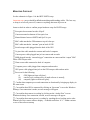
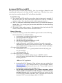
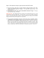
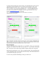
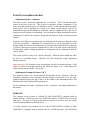
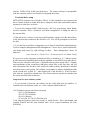
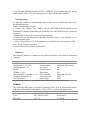
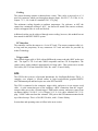
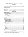
MORIS (MIT Optical Rapid Imaging System) Guide
20080601ff aasg
The short-term goal of this document is to provide a consolidated location for notes on
the setup of MORIS on the IRTF. Longer-term, this document can serve as a basis for the
operating and user manuals.
The official MORIS website is http://occult.mit.edu/instrumentation/POETS/
IRTF/index.html. The Documents tab contains electronic versions of all documents,
user manuals, and schematics. Password protection is user “poets” with password
“POETS@IRTF”.
Table of Contents
Mounting Checklist............................................................................................................ 2
Accessing POETS on the IRTF......................................................................................... 4
Local Observing ......................................................................................................................... 4
Remote Observing...................................................................................................................... 4
Running SpeX for POETS users .............................................................................................. 5
A Brief Camera Software (Solis) User Guide ................................................................... 6
Filter Wheel...................................................................................................................... 11
Data Transfer ................................................................................................................... 12
Fore-Optics and Mounting Box ...................................................................................... 13
Adjustment of the z-extension................................................................................................. 13
Adjustment of mount for lenses 2 & 3 ................................................................................... 13
Computer .......................................................................................................................... 13
Two-hard-drive setup .............................................................................................................. 14
Autologin setup ........................................................................................................................ 15
Software .................................................................................................................................... 15
Camera ............................................................................................................................. 15
Cooling ...................................................................................................................................... 16
PCI interface ............................................................................................................................ 16
Trigger cable ............................................................................................................................ 16
GPS ................................................................................................................................... 16
Index of Figures
Figure 1. Schematic for the setup of POETS on the IRTF _____________________________________ 3
Figure 2. Solis v.4.6.5 (POETS camera software) as it appears upon successful startup. _____________ 7
Figure 3. Data acquisition settings for typical operation of the POETS camera. ___________________ 9
Figure 4. Typical settings for data storage: the “Spooling” and “Auto-save” tabs. _________________ 10
MOUNTING CHECKLIST
See the schematic in Figure 1 for the IRTF POETS setup.
Important note: power should be off when attaching and detaching cables. The best way
to setup is to have all power off, connect everything, then turn all power on.
Items to check in order to confirm proper hardware setup for POETS usage:
! Foreoptics box mounted on side of SpeX
! Camera mounted on bottom of fore-optics box
! Manual shutter between POETS and SpeX is open
! BNC cable attached to GPS antenna at top of telescope
! BNC cable attached to “antenna” port on back of GPS
! Serial octopus cable plugged into the back of the GPS
! 36-pin white cable attached to camera and back of computer
! Camera power cable plugged into jack on camera and an outlet
! SMB plugged into the “external trigger” connection on camera and the “output” BNC
on the GPS octopus cable
! Warm room cable connected to back of computer
! Computer power cable plugged into computer and an outlet
! GPS power cable plugged into jack on the GPS octopus cable and an outlet
! Power on for the following:
(i)
GPS [lights on front will glow];
(ii)
camera [can’t confirm power on until software is started];
(iii) computer [lights on front will glow].
! Confirm that computer power and connection are functional by bringing up display in
the warm room
! Can confirm that GPS is connected by clicking on “Spectrum” icon on the Windows
desktop: if no connection is made, an error message will appear
! Can confirm that camera is working by clicking on the “Andor iXon” icon on
Windows desktop: if no connection is made, an error message will appear
! Can confirm that camera power is working by watching the red cooling notice at the
bottom left of the camera software display – it should read below “0º C” within a minute
or two of the software startup
Figure 1. Schematic for the setup of POETS on the IRTF
ACCESSING POETS ON THE IRTF
There are two ways to run the IRTF POETS. One is by traveling to Mauna Kea and
controlling the instrument locally from the IRTF control room. The other is by remote
observing from a machine that has VNC and sufficient bandwidth.
Local Observing
(1) The computer and GPS should be powered on when the instrument is mounted. If
they are not, follow the cable guide from the camera to the cold bay in which the
computer resides. Press the power switch on the front to turn on power.
(2) There is a workstation with multiple monitors in the IRTF control room facing the
entrance door. Log in using your guest account, and follow the remote observing
instructions below.
(3) The system is now ready to operate. The instructions below for Solis, the GPS
software, and the filter wheel software should be followed.
Remote Observing
(1) To observe remotely, you must first establish a guest account. Use the following
from a terminal line in a terminal window:
a. localmachine% ssh [email protected]
b. password for both stefan and duke is “irtf”
c. enter the PI’s name (e.g. Gulbis)
d. enter the observing program number (e.g. 049)
e. note your guest number (e.g. guest21)
f. assign a password to your account – note that if you make a typo when
confirming your password, you will lose the account. So if you think you
made a mistake when entering passwords, use ctrl-U to delete and reenter.
(2) Login to your stefan account:
a. localmachine% ssh –X -2 -A guest#@stefan.ifa.hawaii.edu (using your
new guest number)
b. enter password from 1.f.
(3) Connect to the POETS computer:
a. Following (2), in terminal window start vnc to POETS: stefan%
vncviewer poetspc (password irtfirtf). This method appears to not require
the daily password.
- OR use a VNC application:
b. download RealVNC Enterprise Client software onto your machine from
www.realvnc.com. Click "Download and try" for the Enterprise Edition,
fill out the form, and then scroll down to the "Viewer Only" section to
download the version for your operating system.
c. Get the daily password from the TO or contact astronomer and the
window numbers for POETS (usually through a virtual machine 13)
and SpeX (directly at 2). You can contact the telescope operator at (808)
974-4210 (or any member of the IRTF staff). The password is used on all
instrument VNC servers and changes daily at 7:00 AM.
d. start VNCViewer application on your machine with the following
parameters:
VNC Server: stefan.ifa.hawaii.edu:13
Password: given that day, changes at 7 AM
A remote desktop will appear on Stefan. From that machine, enter
%vncviewer poetspc (password irtfirtf)
e. Note that the command “vnc –show” gives the display numbers for each
instrument. There are 11 permanent displays assigned to instruments at
this time. They are:
1 - bigdog
2 - guidedog
3 - nsfcam2
4 - nsfcam2
5 - m2 (mirsi2)
6 - m2 (mirsi2)
7 - cshell (instrument)
8 - cshell (guider)
9 - autofocu
10 - t3remote
11 – apogee
Can open t3remote for position and focus change, and for sending next
object coordinates to the TO, by right clicking in guidedog, then selecting
from menu. Alternately, type “t3remote”.
Users are encouraged to use starcat2 to submit targets
(http://irtfweb.ifa.hawaii.edu/~tcs3/starcat2/).
f. To end the session, close the VNC client.
Notes on VNC on the POETS computer
- We installed VNC software onto the IRTF POETS computer (software downloaded
from IfA computer stefan in directory /hilo_shared/win_stuff /software/vnc). It is
configured with password “irtfirtf”.
- VNC service should start automatically on the POETS computer. This computer should
display a small icon on the lower right dock when VNC is running.
- As an IRTF observer, you will be assigned a login as guest# (where # is a number) on
stefan for some days before and after your run. You log in to stefan in order to run
POETS.
Running SpeX for POETS users
a. Follow (3)b & c above.
b. Start VNC on your local machine with the following parameters:
VNC Server: stefan.ifa.hawaii.edu:2
Password: given that day, changes at 7 AM
c. The settings below are standard for using SpeX simultaneously with POETS.
They are altered by clicking on the row of icons near the bottom of the
lefthand GuideDog user window.
Lamp/Mirror = off/out
(*at end of night, put mirror IN*)
Dichroic = 0.9
OS filter = open
(*at end of night, set to 14:blank/closed*)
Rotator = 0.0
Slit = mirror/blank
G Flt = whatever filter desired for guiding and imaging (J is the usual)
d. To end the session, return instrument settings to the positions noted above and
close the VNC client. Do NOT close the instrument GUIs.
A BRIEF CAMERA SOFTWARE (SOLIS) USER GUIDE
The POETS computer is turned on by pressing the silver button on its front. A Windows
XP desktop should appear automatically. If for any reason you need to provide a
password for the IRTF POETS account, it is KBO_occ@IRTF.
The bold text below contains simple instructions for camera operation. Note that the
screenshots in Figs. 2-5 are from an earlier version of the Solis software than that
currently used at the IRTF and thus may be slightly different; however, the instructions
here are valid. A hard-copy user manual is onsite, which describes many other features!
Because there is currently no other location in this document for this note, the image
orientation is such that N is left and E is down.
(1) CLICK on the “Andor iXon” desktop shortcut icon to start the camera software.
(Note that this icon should be near the Spectrum Inst./TM-4 icon that is employed to
monitor and send trigger signals from the GPS. Other software shortcuts are provided
on the desktop for usefulness, but are not necessary to run the instrument).
(2) CONFIRM that the camera software starts and presents a screen like that
shown in Figure 2.
a. Note that the camera S/N should appear in the top bar. This confirms that the
software recognizes the camera.
b. Note that a pre-existing configuration file should be loaded automatically.
This will cause the camera to cool upon startup and ensure that the shutter is
closed. (If you want to change the configuration file, simply set software
parameters to your choosing. Then overwrite the .cfg file listed under File >Configuration Files.)
c. Note that the temperature display in at the lower left is red, which indicates
that the temperature has not stabilized. That box will turn blue when the
camera has stabilized at the set temperature.
Figure 2. Solis v.4.6.5 (POETS camera software) as it appears upon successful startup.
(3) To take data, the shutter must be open. CLICK Hardware->Shutter Control, and
ensure that the Internal Shutter is set to permanently open. For longer exposures,
a manual shutter setting could be used; however, this mode is not tested.
(4) To set data-taking parameters, CLICK on the white wrench icon (denoted by an
arrow in Fig. 3) or use the Acquisition->Setup Acquisition menu. Typically, the
configuration file starts with the settings shown in Fig. 3. The exposure time, number
of exposures, and readout rate amplifier will be the selections that are usually altered
between frames.
a. “Triggering” should be Internal if you plan to take frames using the Solis
software; External Start if you plan to take a data cube containing the
number of frames listed in the Solis software and starting at a GPS trigger;
External if you want the camera to take a data cube containing the number of
frames specified in the Solis software with each frame being triggered by a
GPS repeat signal. See (9) for sending GPS triggers.
Important note: The camera software and GPS software do not communicate with one
another. Therefore, you must hand-record the start time of any images triggered via GPS.
b. Note that the “Shift speed” is the time to shift electrons per CCD row.
Number selections listed in brackets will allow the data to read out even more
quickly, but are likely to incur some electron loss.
c. “Readout rate” allows selection of the amplifier: 1 MHz (Conventional &
Electron Multiplying; EM), 3 MHz (Conventional & EM), 5 MHz (EM) or 10
MHz (EM). Faster readout rates incur higher read noise – see the
specification sheet for details. Note that the EM modes can be run with EM
disabled. Usage of EM modes while disabled removes worry that the
d.
e.
f.
g.
h.
avalanche gain will be compromised; however, taking data in this mode (or
even with EM enabled at very, very low EM values) is inadvisable because
the EM must be high enough to compensate for the higher read noise and
excess noise factor in these modes.
Readout gain, in e/ADU, is selected by choosing “Pre-amplifier gain”. See the
specification sheet for values corresponding to the listed numbers.
The “Number of prescans” can be set to a non-zero value if you would like to
ensure that the first frame of every saved cube does not contain any residual
signal. Note that prescans have not been used with occultation (or other timespecific) observations. We typically drop the first data frame during analysis.
Ensure that the “Frame Transfer” box is checked. The camera has not been
tested in non-frame transfer modes.
Note that frames (.fits or otherwise) can be opened in either the Solis software
(under the File menu) or in ds9
Note that the WinScp icon on the desktop is a user-friendly interface for
transferring files between POETS and stefan, or other remote servers.
Preview
Take Data
Stop Taking Data
Data Acquisition Settings
Figure 3. Data acquisition settings for typical operation of the POETS camera.
(5) To preview data, (take and see frames without storing) CLICK on the video
camera icon labeled “preview” in Fig. 3. The stop button labeled in Fug. 3 will
stop the preview.
(6) To take data, CLICK on the camera icon labeled “take data” in Fig. 3. The stop
button labeled in Fug. 3 will abort.
Important Note: The configuration file is currently set to automatically spool, save, and
incrementally number the data cubes. (See next item.) If you do not want to autospool
and save, you must change these settings. With no spooling, any image you take should
display and then allow you the option to save and name.
(7) To spool and automatically name data, GO TO the Setup Acquisition window
and CLICK on the “Spooling“ and/or “Auto-Save” tabs. The typical settings for
these are shown in Figs.4a & b. Spooling ensures that every frame is saved – when
taking a very large data cube this prevents total data loss should a mid-cube crash
occur. When the “Use Append Setting from Autosave tab” is selected, the spooled
data are compiled into a data cube and named via the pattern selected in “Auto-save”.
Figure 4. Typical settings for data storage: the “Spooling” and “Auto-save” tabs.
(8) To change the cooling settings, CLICK on the menu Hardware->Temperature
Control. Adjust the temperature by entering a value in ºC or moving the adjustment
bar. The cooler should be on and the box for “on at program startup” should be
checked. See Fig. 5 for typical settings.
Figure 5. Typical settings for the
temperature control panel for POETS.
The minimum cooling depends on
ambient temperature: for reference, at
68º F the camera can cool to –60C.
(9) To trigger the camera using the GPS, SELECT all of the acquisition settings you
desire. CLICK on the camera icon to take data. Next, enter the GPS software
and select POP (lower right). Set start time (UT) and repeat interval, as desired.
The camera will sit until it receives the trigger (at the POP time you set), at which
point frames will display in the software.
Important Note: Again, note that the GPS start time is NOT RECORDED anywhere
other than when you type it into the GPS software. The time in the FITS header will be
that when the take data command was given in the Solis software.
(10) To close the software, simply click File->Close. The camera fan may continue to
run if the software is closed but the computer is still running. It is best to shut down the
entire system at the end of each night.
FILTER WHEEL
There is a GUI on the POETS computer screen that allows control of the filter wheel. Fig.
6 shows screen shots of the GUI upon startup and when connected.
(1) Click on the icon “shortcut to smgui” on the desktop. A screen shot of the
display is shown below.
(2) Click the “connect” button. The computer will interface with the filter
wheel an initialize to position 1.
(3) To change to the desired filter, select the filter from the drop-down menu
under “Control”. Then click “move to”.
(4) Close the GUI by clicking the red X in the upper right corner.
To change the filter listing in the control software, the SmartMotorGUI.java file must be
edited and recompiled. Edit the file in a text editor (such as Komodo). Then, on the
POETS machine, go to Start -> Run -> and type “cmd”. Cd into the smgui directoy
(“dir” to see files). Type “make SmartMotorGUI.java”. A new SmartMotorGUI.class
file will be created and the GUI will update. Provide a copy of the new file to Tony
Denault ([email protected]) for archiving.
Note: notes for Java installation and other filter software are online at
irtfweb.ifa.hawaii.edu/~poets.
Figure 6. The filter wheel GUI. (left) Upon start up, the “connect” button is highlighted and
must be pressed to gain control. (right) Once connected, the desired filter can be selected
from the drop-down menu located under in the “Control” section.
DATA TRANSFER
Currently, the only method to transfer data is to use WinSCP. There is an icon for this
program on the desktop, from which you can connect to a local machine and transfer
data. This process must be done from the POETS computer and does take a long time.
SpeX data are in the directory /scrs1/. They are compressed after 5 days and deleted after
14 days (although the data are permanently archived weekly). Data should transferred to
a local machine using sftp, scp, or rsync.
Xx need a more permanent methodology for this, given other users
FORE-OPTICS AND MOUNTING BOX
Adjustment of the z-extension
The camera can be focused by adjusting the “z-extension”. This is the threaded plate
system at the base of the box. This system is comprised of three components: (i) an
inner- threaded aluminum piece (32 threads per inch), (ii) and outer-threaded steel plate
which screws into (i) allowing for a range of xx inches vertical motion, and (iii) an
aluminum base plate which attaches to (i) and the camera. Component (ii) sets the camera
height and can be adjusted via threading. By loosening the sliding attachments between
components (i) and (iii), the camera is decoupled and can move in the z-direction without
rotation.
In practice, the sliders on component (iii) are loosened and the camera is allowed to drop
to the lowest position. Component (ii) is threaded into or out of component (i) to the
desired height. The camera and component (iii) are then lifted until flush with component
(ii) (there is fitted groove between components (ii) and (iii) in order for the connection to
be light tight), and the sliding attachments on component (iii) are tightened to hold the
camera in place.
The system should be setup to be cofocal with SpeX. Different filters should not effect
the focus to a detectable degree. Therefore, the focus should not require adjustment
during regular use.
Important note: The focusing system was designed to allow for maximum range. If the
camera is lifted to the highest position, the mount for lenses 2 & 3 could impact the
shutter and/or camera window. Be careful!
Adjustment of mount for lenses 2 & 3
The mount for lenses 2 & 3 was designed to be adjustable in the z direction. Thus, the
mounting component screws into the mounting bracket with threads of 14 per inch.
Optimal alignment places the top of lens 2 in the middle of the mounting bracket. This
should not need to be adjusted during regular use.
See the important note under “adjustment of the z extension” concerning adjustment of
this mount.
COMPUTER
The computer for this system is a Shuttle G5 6800 (SN68PTG5), configured with an
Athlon dual-core 2.6GHz processor, two 2GB RAM, and two 150GB SATA 10,000 rpm
hard drives. The goal is to setup the hard drives such that if one drive fails, the system
can be run independently on the other drive.
A second computer was purchased for use with the IRTF POETS, a Shuttle G5 6800
(SN68PTG5), configured with an Athlon dual-core 2.6GHz processor, two 2GB RAM,
and two 150GB SATA 10,000 rpm hard drives. The camera software is incompatible
with this computer, and we are currently investigating the reason.
Two-hard-drive setup
IRTF POETS computers have Windows XP Pro. (32-bit) installed on two separate hard
drives. Details on how to enable disk drives, change the boot order, and install windows
separately on each drive are below.
• To get to the computer BIOS, hold down the “del” key upon startup, when Shuttle
screen is viewable. Select “Advanced” and “Boot configuration” to change the order of
the start up disks.
• If the disk is new, or there is a need to reinstall windows, simply select the desired drive
as the first boot drive and insert the Windows CD. You will be prompted to boot from
the disk.
• To see disk drives and their configuration, go to Start!Control Panel!Administrative
Tools!Computer Management!Disk Management. Can see drives, enable and disable,
and change path letters by right clicking on them. “Drive Management” shows all
hardware.
(note: must be in “Classic View” of control panel to see Admin. Tools)
We cannot set up the computers such that each drive is bootable as “C:/” and has camera
& GPS software preinstalled (thus having the capability to run POETS from either drive).
There are two reasons for this issue: (i) installed software often assumes the C: filepath,
and installations on the second drive will place critical files on the first drive and will
thus not function if the first drive fails, and (ii) the Andor software should not be installed
more than once on any system. The solution is to maintain a software installation folder
on the second drive (called “E:/” when booting off of the first drive). If the first drive
fails, then the second drive should boot. The critical software can then be installed and
the system should be able to function.
Setup notes for new windows system:
• To get network to function, the software on the nvidia disk must be installed. It
contains drivers for Ethernet, audio, etc. It also contains Adobe Reader 8.1.
• Set IP address using an extra from our group:
18.83.3.196 (Exoplanet)
255.255.255.0.0 (Mask)
18.83.0.1 (Router)
18.70.0.160, 18.71.0.151 (DNS Servers)
Used Internet Explorer (from start menu) to install Firefox. Then, downloaded and
installed WinSCP and ds9, then installed Solis 4.6.5.0 (copied installation file from
ASTRON).
• The software installation folder on MIT’s ASTRON server contains software for the
Andor camera, GPS, VNC, and Virus protection. These should all be installed.
Autologin setup
To allow the computer to automatically login on start up (or to disable this feature) use
the following process:
• Start > Run and type “regedit”.
• Locate the registry key HKEY_LOCAL_MACHINE\SOFTWARE\Microsoft\
WindowsNT\CurrentVersion\Winlogon and double click the DefaultUserEntry, then type
user name
• Double click on DefaultPassword and enter password
• Double click on AutoAdminLogin and under ValueData enter “1” for automatic or “0”
for non-automatic login
• Note: if DefaultPassword or AutoAdminLogin values do not exist, simply use Edit >
New> String Value to create them
• Must restart for these changes to take effect
Software
The following software is installed on the primary hard drive of the POETS instrument
computer:
Program
Adobe Reader v. 8.1
*Andor Solis v. 4.8.3.002
*SAOImage ds9 v. 5.2
FireFox
*WinScp v. 4.3.1
*Spectrum TM-4 controller v.1.36
VirusScan Enterprise 8.5i
VNC Dimension
Function
.pdf viewer
camera control
.fits viewer
internet browser
file transfer
GPS controller
Virus protection
remote login
License Information
free
Purchased with camera
free
free
free
Purchased with GPS
MIT
IRTF
*Installers for this software are also located in a folder on the desktop of the second hard drive.
CAMERA
The camera for this system is an Andor Technology iXon. It is an off-the-shelf camera,
with a back-illuminated, frame-transfer CCD (512 x 512, with 16 µm square pixels).
Model
Serial Number
Camera:
DU-897E-CS0-#BV
X-3020
CCD:
E2V TECH CCD97
05445-04-23
PCI Card:
CCI -22
C-1188-B
Cooling
The camera housing contains a thermoelectric cooler. This cooler is powered via a 2.1
mm Jack connector which goes through an adapter (Input: 100-250 V, 47-63 Hz, 0.4 A,
Output: 7.5 V, 4.0 A) and to a standard 120 V U.S. plug.
The minimum cooling depends on ambient temperature. For reference, at 68ºF the
camera has a minimum cooling of -60ºC. An alarm will sound if the camera overheats,
which can happen if the air vents are blocked.
Additional cooling can be achieved through water cooling; however, this method has not
been tested for the IRTF POETS system.
PCI interface
The controller card for the camera is a !-size PCI card. The camera-computer cable is 6m long and has proprietary 36-way connectors. PCI card and cable are provided by
Andor Technology.
Trigger cable
The external trigger cable is 50 " with an SMB on the camera end and a BNC on the user
end. The input is TTL level and CMOS compatible and has 470 " impedance. The
camera comes with a standard, approximately 6-ft long cable. This system uses a custom
20-ft cable (RG174) from Stonewall Cable, Inc. with 1.54 nsec/ft delay.
GPS
The GPS for this system is a Spectrum Instruments, Inc. Intelligent Reference TM-4. A
complete user manual is located online at http://occult.mit.edu/_graphics/POETS/
info/TM4manual.pdf and hard copies are at the IRTF and MIT.
The GPS is connected to the computer, trigger cable, and power via an octopus serial
cable. A serial connection goes to the computer, a BNC connection from the “output”
octopus cable goes to the “external trigger” SMB on the camera, and power comes from
an adapter (Input: 120-140 V, 0.4 A, Output: 24 V, 0.4 A) with a standard 120 V U.S.
plug. A BNC cable runs from the “antenna” GPS port to the GPS antenna mounted at the
top of the telescope. This is a 50-ft RG-58 cable, with 1.54 nsec/ft delay.
Screen shots and operating notes to follow in the next version.