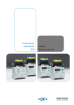
1
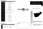
 *
!"#$$%&'()&&
Continuous measurement of micro resistance in
solder joint area and connector contact area.
Efficient evaluation of the reliability of connections
The Conductor Resistance Evaluation System enables continuous
measurement of resistance changes under high and low temperature cycle.
Automatic measurement, data storage and processing are operated systematically with a PC.
The system realizes accurate and effective contact reliability evaluation.
1
2
MEASUREMENT EVALUATION SYSTEMS
■
MAIN USE
● ● ● ● ● ● ● ● ● ● ■
MAIN FEATURES
● "#$% &%'#()" )"* #"+")#,")' ()"*)+*(,&-)#.' &)(%+&" $%#-&"
● #+ %++" )--'#)#," )"* )'+")#"/ %++" )--'#)#,"
● .(,'% 0)'% 0)'%)#," )"* +) ,1 2)"/ 0)'%)#," )+ )0)#').'
● )' #& &)(%+&" #( ").'* %(#"/ ) -+(,")' ,&-%+
)) *##"/ )"* *)) .+,3(#"/ )+ )0)#').' *%+#"/ 2 &)(%+&"
● "+)#," 3#2 2 2+&)' (2,4 2)&.+ *+)&)#)''5 #&-+,0( 2 ( 11##"5
● ● ● ● ● ● ● ● ● 3
! ● Utility
Using the international standard traceable precision instrument
guarantees most accurate and compatible measurement data.
We have always earned our
customers’ confidence
AMR is equipped with highly reliable
measurement equipment and an
ammeter for micro resistance meter that
are designed to meet international
standards in order to obtain most
reliable measurement data. We offer a
calibration service to maintain the
equipment’s accuracy (ISO / IEC 17025
compliant).
We offer two current
applications, DC and AC
We offer two micro electric current
applications, the DC (AMR-PD) and the
AC (AMR-PA), which are used to apply
current to specimens when measuring
the conductor resistance.
Measurement of a wide range
of resistance from 10−3 to 106 Ω
Conductor resistance values ranging
from 10−3 to 106Ω(AMR-PD) and from
10−3 to 104Ω(AMR-PA) can be measured
accurately at the tip of a measuring
cable, using a four terminal method.
AMR
Multi-channel continuous
measurement dramatically
improves the work efficiency
Channels can be added in 40-channel
blocks from the standard 40 channels up
to 280 channels (optional) depending on
the tests and the number of chambers to
be connected.
Measurement equipment (Agilent Technologies)
4
Utility
Multifunction rack that pursues ease of use improves the workability.
Connection unit
Installing the connection unit facilitates
the measurement cable connection. The
connection unit can be installed in front of
the rack or on the left or right side of the
rack according to the work environment.
Cable that has excellent heatand noise-resistance
characteristics
A flat cable made of Teflon is used. The
excellent heat- and noise-resistance
characteristics of the Teflon flat cable
enable accurate measurement of microresistance. The end of the cable is
designed to facilitate the connection to a
specimen.
Global environmental problems
Components are mounted by lead-free
soldering. In addition, power consumption
is reduced by 24% (in comparison with
the previous model) in consideration of
global environmental problems.
System rack
Connection unit
Mesurement cable (Chamber sold separately)
5
*except for purchased items such as PCs and
measuring instruments.
Utility
Tests simplified by interaction of the measurement system
with various environmental test chambers.
Interaction with the
environmental test chamber
AMR can connect up to three environmental
test chambers for testing. Interaction
with the environmental test chamber
enables temperature and humidity
monitoring, management of the time
schedule, and displays an alarm when a
failure is detected.
Real-time monitoring of
temperature and humidity
AMR monitors and records the temp.
and humid. inside the environmental test
chamber. Data is recorded simultaneously
with the measurement by the
measurement system. The statistics
processing software displays the
recorded data in synchronization with
the data of the resistance value.
Safety design guaranteed by
abnormality detection
If a problem occurs with the environment
test equipment or AMR, the test will stop.
Resetting will resume the test from where
it stopped.
Remote processing of the
test data (optional)
LAN-compatible software enables
remote test checking and data processing,
such as from a remote office.
Additionally, we offer software licenses
according to the number of users so that
multiple PC monitoring is possible.
An interaction with the Thermal shock chamber
Function
Interaction with the thermal shock chamber (TSA Series)
Temperature
monitoring
Reads the temperature with respect to each measurement by
the measuring equipment. Finally transfers data to the CSV file.
Cycle count
Reads the cycle counting of the chamber and saves the
number of failure occurrences.
Start of the test
AMR starts the test. Test automatically starts when the
chamber is ready for test.
Halt of the test
When AMR halts the test, automatically halts the operations of
the chamber and AMR after being exposed to high temperature.
Resumption of the test
Automatically resumes the halted cycle of the test as it
is. The halt history is saved in the measurement data.
Completion of the test
Test automatically ends when the test completion condition is met.
Work temperature
monitoring
Measures temperature uniformity in the chamber up to 16 channels
and saves data in the CSV file on the measurement basis.
Chamber failure
detection
When a failure occurs in the chamber or the measuring
equipment fails to operate properly, the test automatically stops.
Data processing
Checks the obtained temperature data against the data of
resistance values based on the number of cycles.
Network
Windows
R
AMR
6
Evaluation
Two failure recognition methods are available to detect the failure in
conductive resistance change at inter-connects.
Failure recognition using
the absolute value
Absolute value evaluation
■ Absolute value setting
Failure recognition using
the change rate (%)
This method can be used to detect small
change of conductive resistance of BGA
and CSP. It will compare initial value at
the start point of the test and using %
change to recognize the failure. It can
be set on both side of hot and cold
conditions.
Rate of change evaluation
! ! ■ Rate of change setting
7
The measured date obtained at
measurement intervals is evaluated
using the preset absolute value. It will
detect small change of conductive
resistance change due to micro-cracks
up to complete open.
You can set the absolute value in hot
condition and cold condition to have
separate recognition available both side
of temperature. AMR will terminate the
test on the channel that failure once
recognized. (It can be set to resume the
test too.)
! ! Evaluation
DC or AC measurement can be selected according to your test requirements.
DC Measurement (AMR-PD)
Using DC current resistance to measure
small voltage change and detect up to
1M ohms of resistance. It is useful to
observe large change of conductive
resistance such as Daisy Chain of BGA
in semiconductor applications.
AC Measurement (AMR-PA)
Using AC micro current to measure
small voltage change without affected
by thermal electromotive force. It is
useful to observe the change of
conductive resistance in contact
resistance evaluations.
◎
◎
◎
○
△
◎
" #
○
◎
$%
" " #
△
◎
◎
◎
◎
◎
!
% %
!
●
& %
$%
' $
%
$%
% %
%
$%
$
%
% %
& %
%
+%
*%
)%
(%
●
! & %
$%
%
' $% % %
$
%
+%
*%
,%
(%
-%
.%
/%
)%
0%
1 ' %
% ' #
8
SOFTWARE
● Main
window*
・Test monitoring
・Real time display of the resistance value, temperature
inside the chamber, channel on which a failure occurs
・Auto link to the data processing software
・Test control (start, stop, pause, and restart)
* The picture above shows AMR-280-PD.
● Test
condition registration
● Registration
of the test conditions
On this window, you select a module,
input the data file name, set the
interacting chamber, output test data,
input presence or absence of the leaktouch behavior mode and comment,
select test channels, and specify the test
condition. (Select a test condition from the
test condition file.)
Duration and cycle of a test and
measurement, measurement voltage,
stress-application voltage, and limit values
are saved as a test condition file. Multiple
test conditions can be saved depending
on the specimen and test conditions.
● Graphic
● Cursor
display
Graph can be arranged by choosing
channel display, display setting, and
cursor display.
Graphs can be copied on a clipboard to
be applied onto another software.
The sample graph displays resistance
value with temperature on thermal
shock chamber at the same time.
9
function
Quick confirmation of measurement data
and channel number by cursor function on
graphic display.
● Weibull
Analysis (Optional)
Data-processing software (with a
statistical processing function) enables
Weibull analysis of test data, as well as
the plotting of normal probability and
logarithmic-normal probability.
SYSTEM BLOCK DIAGRAM
-# %
-# 3
4 #
-#
5"49 ;
:8
! " #
$ % $ & "# ' #
( "" )* +, -
"# ". *
-
-
-
-
●
・-# /
" 1 # *
. " 2. *
・3 4 # /
% 4 # # *
# 4 *
5 4 !. 4 ""* " #
●
・
/
# # (4 *
1 #/ 6" 4 7((+ " # 2 $
2
#/ 6" 4 (77, " # 2 $
2
・
/
( "" 8#. +, """
・ /
4 "# . 2.
# *
・
/
9# *
・ /
2 " 10
SPECIFICATIONS
.
&
'
16
01
A
8
: $ 1 1
'//$%
'//$
% ! " #$
( , -. (/
(
× × ) *
× ( × *
+*
+*
* & ±47 *, *, *, *, *, *,
*, *, *, *, *,
*, @09
*, *, @09
2/ .
0 0 13 +45
? 3 4
?1 3 4
9 /
3 ( 0
3 ((? 0
4(! × ;42 × %<% - , >, - , >, (
- , >, 4
- , >, −
−
6- . 1
MODEL
AMR -
ACCESSORIES
-P
●
●
D: DC application
A: AC application
Number of channels
040 : 40 channels
080 : 80 channels
120 : 120 channels
160 : 160 channels
200 : 200 channels
240 : 240 channels
280 : 280 channels
11
●
●
●
●
●
User’s manual
System controller
Uninterruptable power supply
Micro-resistance measurement unit
Setup CD
GPIB board
PPI board
OPTIONS
Additional channel (40 channel basis)
1m-extension of
the non heat-resistant measurement cable
The channels can be added according
to the capacity of the system (280
channels at maximum on 40 channel
basis).
We elongate the cable that connects the
measurement unit to the connecting
unit. (Selectable at the time of purchase)
Specimen temperature monitor
3m-extention of
the non heat-resistant measurement cable
Emergency stop switch
Stops the system immediately.
Communication cable
E-BUS
Specimen temperature monitor
measures the surface temperature of
the specimen and saves the specimen
surface temperature and the measured
data simultaneously. The following
three types are available.
・4 point measurement type
・8 point measurement type
・16 point measurement type
5, 10m
We extend the cable according to the
installation conditions for the equipment.
* Data correction by our field service
agent is necessary after the initial
shipment and in the case where the
lengths of all cables are changed.
1m-extention of
the heat-resistant flat cable
LAN-compatible software
LAN-compatible software enables
remote test checking and data
processing, such as from a remote
office.
* License for multiple PC monitoring
requires an additional cost.
Data processing software
(with statistical processing software)
We elongate the cable that connects
the connecting unit to a specimen.
(Selectable at the time of purchase)
Heat-resistant Teflon cable
Identical to the heat-resistant Teflon
cable in the standard accessories
・1.5m
Weibull analysis is installed in addition
to the standard statistical processing
software.
Color measurement cable
(150℃ heat-resistance)
Cables whose color varies depending
on the channel
・1.5m
12
VARIOUS ENVIRONMENTAL TEST CHAMBERS〈SOLD SEPARATELY〉
Thermal Shock Chamber TSA Series
TSA series is the series that reduces the temperature
recovery time, temperature heat-up time, and temperature
pull-down time. TSA series has HFC refrigerant and a
touch-panel that facilitates operation setting changes.
TSA Series is the environment-friendly series.
TSA―71S
TSA―101S
TSA―201S
TSA―41L
TSA―71L
TSA―101L
TSA―301L
W410×H460×D370
High temp. chamber:+60∼+200℃
W650×H460×D370
Low temp. chamber:−70∼0℃
W650×H460×D670
W240×H460×D370
High temp. chamber:+60∼+200℃ W410×H460×D370
Low temp. chamber:−65∼0℃
W650×H460×D370
W970×H460×D670
Thermal Shock Chamber TSD-100
TSD-100 is a thermal shock chamber with two zones that
conform to Japanese and overseas test standards such as
MIL-STD-883, JIS C 0025 and JASO-D001. With
excellent temperature distribution performance, this
chamber applies uniform temperature stress to specimens.
Furthermore, by monitoring specimen temperature with
the STT function, this chamber starts counting exposure
time and switches to the next step immediately after the
specimen temperature reaches a preset value, thus enabling
highly accurate tests. In the temperature range between
60℃ and 150℃, this chamber has a short return time of 15
minutes, resulting in reduction of total test time. This
chamber can be used for a variety of activities, from
research and development to inspection and production.
TSD―100
13
High temp. chamber:+60∼+200℃ W710×H345×D410
Low temp. chamber:−65∼0℃
ESPEC CORP. has been assessed by and registered
in the Quality Management System based on the
International Standard ISO 9001:2000 (JIS Q 9001:
2000) through the Japanese Standards Association
(JSA).
ESPEC GROUP
ESPEC CORP.
ESPEC ENGINEERING CORP.
ESPEC KANSAI CORP.
ESPEC ENVIRONMENTAL TEST
TECHNOLOGY CENTER CORP.
ESPEC BUSINESS CREATE CORP.
344
4
2 3-5-6, Tenjinbashi, Kita-ku, Osaka 530-8550, Japan
Tel : 81-6-6358-4741 Fax : 81-6-6358-5500
Tel : 1-616-896-6100 Fax : 1-616-896-6150
! " Tel : 1-408-592-4059 Fax :1-408-778-4353
#$
Tel : 49-89-18939630 Fax :49-89-189396379
% &#' (
2 Tel : 86-21-51036677 Fax : 86-21-63372237
,#+5+"6 * Tel : 86-10-64627025 Fax : 86-10-64627036
6"672 * Tel : 86-20-83317826 Fax : 86-20-83317825
2#"72#" * Tel : 86-755-83674422 Fax : 86-755-83674228
72 * Tel : 86-512-68664007 Fax : 86-512-68601994
8+ * Tel : 86-510-82735036 Fax : 86-510-82735039
#" &#' (
Tel : 86-21-68798008 Fax : 86-21-68798088
&"' ( )(
Tel : 60-3-89451377 Fax : 60-3-89451287
● ●
●
+&&,&-$. /! "0 .$$)1
R