1
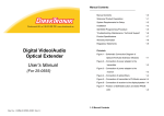
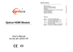
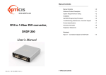
Manual Contents __________________________________________ ® www.opticis.com Stretch FireWire TM Manual Contents Welcome!, Product Description System Requirements for Setup Installation Troubleshooting, Maintenance, Technical Support Product Specifications Warranty Information Regulatory Statements 1-0 1-1 1-2 1-3 1-6 1-7 1-8 1-9 Pictorials Figure 1 – Firewire repeater system with optional fiber cables Figure 2 – End View of M4-200 Repeater Figure 3 – Side View of M4-200 Repeater Figure 4 – End View of M4-201 Repeater Figure 5 – Side View of M4-201 Repeater 1-1 1-3 1-3 1-4 1-5 User’s Manual M4-200 & 201 Doc No. : OEB-D130903-M4 / Rev1.1 1- 0 Manual Contents Welcome! Congratulations on your purchase of the Stretch Firewire M4-200/201 Optical FireWire Repeater System. This manual contains information that will assist you in installing and operating the product. System Requirements for Setup Hardware requirements port in your PC or Mac systems. Product Description Shipping Group AC/DC power adapter: One (1) unit User’s Manual Duplex LC Multi-Mode Optical Fiber Cable: Optional, can be provided by the user or by the reseller. controllers. Step by step connection of Multiple M4-201s is strongly recommended prior to install all M4-201 boxes in a time. Software requirements No special restrictions, if you’ve already properly installed your 1394 controller in your OS. M4-201 M4-201 Optical Firewire Repeater : One (1) unit 0.7 meter 1394b copper cable : One (1) unit No special requirements memory size, CPU speed and chipsets, if you’ve already properly installed your 1394 M4-200 M4-200 Optical Firewire Repeater : Two (2) units 0.7 meter 1394b copper cables : Two (2) units 2pcs x Bilingual port(9pin) to DS port(6pin) for S400 or 2pcs x Bilingual port(9pin) to Bilingual port(9pin) for S800 You have to have a 1394(a/b) controller having a DS / bilingual Precaution: Before using Opticis M4-200/201, you have to 1pcs x Bilingual port(9pin) to DS port(6pin) for S400 or 1pcs x Bilingual port(9pin) to Bilingual port(9pin) for S800 confirm to install proper device drivers, which the device AC/DC power adaptor : One (1) unit User’s Manual Duplex LC Multi-Mode Optical Fiber Cable: Optional, can be provided by the user or by the reseller manufacture supplies, designed for your operating system. If not, Opticis M4-200/201 might not work. AC/DC Power Adapter Technical Advisory When IEEE 1394 (Firewire) devices or controllers are self-powered, the Power LED is illuminated and the shipping group’s external DC power adapter is not required. Use only if the Power LED is off when the entire system is powered up. The power adaptor in the shipping group can supply to 1394 device up to 12V 1A (12W) through M4-200/201. Tip: This installation advisory is highlighted to avoid power conflicts between self-powered devices and controllers, and unnecessarily applied external power. Figure 1 – Firewire repeater system with optional fiber cables 1-1 Welcome, Product Description 1-2 System Requirements for Setup Installation Important: Please use the installation procedure below. Improper, or no operation may result if the start-up sequence is not correctly followed. Step 1 Carefully unpack the contents of the shipping group and Ensure no host or peripheral equipment is powered up. Step 2 The M4-200 Firewire repeater boxes are identical. Identify one as upstream (or host) and downstream (or peripheral). Step 3 Prepare a duplex LC patch cord fiber-optic cable (Multi-Mode Glass Optical Fiber with 62.5/125 µm or 50.0/125 µm core). Attach the two LC connector fiber cables first with no power applied to any system component as follows: Tx (Upstream) to Rx (Downstream) Rx (Upstream) to Tx (Downstream) Step 6 Power on the host and peripheral equipment. At this point, there must be no external power supplies plugged into the M4-200 upstream or downstream boxes. Step 7 Observe the Power Light Emitting Diode on the side of the boxes. If the upstream box LED is illuminated, no external power supply is required. Likewise if the downstream box LED is illuminated, no external power supply is required. Step 8 If both Power LEDs are illuminated, then the Firewire link is active. Proceed with the software bring-up on the host system. Ignore further steps Step 9 If one or both of the upstream/downstream Power LEDs are dark, then power down all equipment and plug in one or two Opticis power supplies. Step 10 Power on complete system. Both upstream/downstream LEDs should be illuminated. Proceed with host software bring-up. M4-201 installation (Daisy-Chain) Figure 2 – End View of M4-200 Repeater Step 4 Connect the upstream box to the host computer using a copper Firewire cable by plugging into the host computer Firewire card and the upstream box Firewire port (either one). Connect the downstream box to the peripheral equipment in a similar manner. Step 1 Power off M4-200, host and peripheral equipment first. Prepare two duplex LC patch cord fiber-optic cable (Multi-Mode Glass Optical Fiber with 62.5/125 µm or 50.0/125 µm core). Attach the four LC connector fiber cables with no power applied to any system component as follows: Tx (M4-200) to Rx (M4-201) Rx (M4-200) to Tx (M4-201) Step 5 If there are non-Opticis external power supplies to be attached, do so now. e.g. block power supplies for laptop Firewire PC cards, downstream appliances, etc. Do NOT attach the Opticis power supplies until instructed to do so. Figure 4 – End View of M4-201 Repeater Figure 3 – Side View of M4-200 Repeater 1-3 Installation Step 2 Connect the M4-200 box to the host computer and M4-201 to the peripheral equipment using a copper Firewire cable and attach two LC connector fiber cables in between M4-200 and M4-201 boxes. 1-4 Installation (continued) Step 3 If there are non-Opticis external power supplies to be attached, do so now. e.g. block power supplies for laptop Firewire PC cards, downstream appliances, etc. Do NOT attach the Opticis power supplies until instructed to do so. Figure 5 – Side View of M4-201 Repeater Step 4 Power up the host and peripheral equipment. At this point, there must be no external power supplies plugged into the M4-200 or M4-201 boxes. Step 5 Observe the Power Light Emitting Diode on the side of the boxes. If the M4-200 box LED is illuminated, no external power supply is required. Likewise if the M4-201 box LED is illuminated, no external power supply is required. Step 6 If both Power LEDs are illuminated, then the Firewire link is active. Proceed with the software bring-up on the host system. Ignore further steps Step 7 If one or both of the M4-200/M4-201 Power LEDs are dark, then power down all equipment and plug in one or two Opticis power supplies. Step 8 Power up complete system. Both M4-200/M4-201 LEDs should be illuminated. Proceed with host software bring-up. Step 9 If you have another M4-201, follow as Step 11 and connect the duplex LC multimode fiber cables to the next M4-201 as Step 12. The fiber connection is accomplished between the OUT of the prior M4-201 and the IN of the next one. You have to repeat Step 13 to 18 as many as you have. Troubleshooting The Power LEDs are not illuminated. Ensure that all AC and DC plugs and jacks used by external power supplies (both Opticis and others) are firmly connected. Ensure that power bars are live. No controller or driver for the peripheral device exists in the Operating System (OS) device manager. Reset the system. Disconnect and reconnect 1394(b) copper cables or DC power adapters. Check if the two fibers are properly connected. The Tx in one repeater goes to the Rx in the other and vice-versa. Remove the fiber cables and use a Firewire copper cable to connect the upstream and downstream boxes by plugging in to the unused bilingual ports. The OS device manager shows the Firewire connection, but the Firewire peripheral does not work properly. Ensure that the correct software device driver is loaded on the processor platform. Direct connect the peripheral to the processor’s Firewire port to confirm operation. Software drivers are usually available from the Internet. Maintenance No special maintenance is required for the optical repeater boxes and power supplies. If not in use, insert the factory provided plug into the Tx/Rx fiber port. Ensure that the repeaters and power modules are stored or used in a benign environment free from liquid or dirt contamination. There are no user serviceable parts. Refer all service and repair issues to Opticis. Technical Support and Service For commercial or general product support, contact your reseller. For technical service, contact Opticis by email [email protected] or visit our website at www.opticis.com The M4-201, giving connection of a 1394 device is capable of two-way fiber connection in forward and backward directions, which eventually makes a daisy chain with each repeater of M4-200 at both ends. Do NOT plug in external power to the box if the PWR LED is on after the M4-200/201 repeater is connected to a live host or powered peripheral. 1-5 Installation (continued) 1-6 Troubleshooting, Maintenance, Technical Support Product Specifications Warranty Information M4-200/201 Optical Firewire Repeater 1 (One) Year Warranty Electrical Specifications Fully supports provisions of IEEE1394b-2002 M4-200: 2 bilingual ports, M4-201: 1 bilingual port Power supply: DC12~16V (max.500mA) Data rates: S100 (98.304 Mbps), S200 (196.608 Mbps), Opticis warrants this optical Firewire repeater to be free from defects in workmanship and materials, under normal use and service, for a period of one (1) year from the date of purchase from Opticis or its authorized resellers. If a product does not work as warranted during the applicable warranty period, Opticis shall, at its option and expense, repair the defective product or part, deliver to customer an equivalent product or part to replace the defective item, or refund to customer the purchase price paid for the defective product. S400 (393.216 Mbps) and S800 (983.04 Mbps) All products that are replaced will become the property of Opticis. Optical Specifications IEEE1394b-2002 compliant Duplex LC type optical port supporting 62.5 µm, 50.0 µm Multi-mode Glass of Fiber Laser Class 1 Eye Safety compliant: 850nm VCSEL Data rates: S100 (122.44 Mbps), S200 (245.76 Mbps), Replacement products may be new or reconditioned. Any replaced or repaired product or part has a ninety (90) day warranty or the reminder of the initial warranty period, whichever is longer. Opticis shall not be responsible for any software, firmware, information, or memory data of customer contained in, stored on, or integrated with any products returned to Opticis for repair under warranty or not. S400 (491.52 Mbps), S800 (983.04 Mbps) Warranty Limitation and Exclusion Mechanical Specifications M4-200/201 Box dimensions: 101mm / 24mm / 91mm (W/H/D) M4-200 Weight: 0.252 Kg M4-201 Weight: 0.290 Kg Opticis shall have no further obligation under the foregoing limited warranty if the product has been damaged due to abuse, misuse, neglect, accident, unusual physical or electrical stress, unauthorized modifications, tampering, alterations, or service other than by Opticis or its authorized agents, causes other than from ordinary use or failure to properly use the Product in the application for which said Product is intended. Environmental Specifications Operating temperature: 0°C to 50°C Storage temperature: - 30°C to 60°C Humidity: 5% to 95% AC/DC Power Adapter Power Input: AC 100-240V, 50/60Hz 0.1A Power Output: +12 V, 1.0A SMPS DC-power Adapter Cord DC Jack: Core is 12 V and outer is GND. 1-7 Product Specifications 1-8 Warranty Information FCC Statement © 2013 Opticis Co., Ltd. All Rights Reserved Revision 1.1. 3, Sep, 2013 This device complies with part 15 of FCC Rules. Operation is subject to the following two conditions: (1) this device may not cause harmful interference, and (2) this device must accept any interference received, including interference that may cause undesired operation. This equipment has been tested and found to comply with the limits for a Class A digital device, pursuant to part 15 of FCC Rules. These limits are designed to provide reasonable protection against harmful interference when the equipment is operated in a residential installation. This equipment generates, uses, and can radiate radio frequency energy and. if not installed and used in accordance with the instruction guide, may cause harmful interference to radio communications. However, there is no guarantee that interference will not occur in a particular installation. If this equipment does cause harmful interference to radio or television reception, which can be determined by turning the equipment off and on, the user is encouraged to try to correct the interference by one or more of the following measures: Re-orient or relocate the receiving antenna. Increase the separation between the equipment and the receiver. Connect the equipment into an outlet on a circuit different from that to which the receiver is connected. Consult a service representative for help. Properly shielded and grounded cables and connectors must be used in order to comply with FCC emission limits. Changes or modifications not expressly approved by the party responsible for compliance could void the user s authority to operate the equipment. Optical Safety Statement The Opticis M4-200/201 repeater uses an 850nm Multi-Mode Vertical Cavity Surface Emitting Laser diode transmitter that has been designed to meet Class 1 eye safety. Opticis Locations Headquarters Opticis Co., Ltd. # 16Fl, Kins Tower 8 Sungnam-daero, 331 beon-gil, Bundang-gu, Seongnam-si, Gyunggi-do, 463-844 South Korea Te l: +82 (31) 719-8033 Fax: +82 (31) 719-8032 www.opticis.com For order support, please contact your Distributor or Reseller. For technical support, check with the Opticis web site www.opticis.com or contact [email protected] 1-9 Regulatory Statements