1
SPACE ALLOCATION Modeling
ShipConstructor will arbitrarily choose one of them and then ask you if you would like to use the other direction
instead.
•
Align to WCS – Aligns the NavAid such that its spikes are directed along world axes (only available in certain cases
when the NavAid already lies in a world plane).
Offset routing options
These options affect your current routing offset (see Offset Routing (page 12)).
•
XOffset/YOffset – Prompts you to type the new X or Y component of the routing offset, respectively.
•
Choose offset – Allows you to choose a routing offset visually; you will type the letter corresponding to one of several
named points on the bounding box of the space allocation’s profile at the current end.
Creating Connections While Routing In End Mode
Connection creation is initiated by clicking an existing free space allocation end when picking the first point or by clicking
anywhere on the centerline.
1.
Click a point to determine the direction, or if you selected an object coordinate system on the header part, enter a
distance along its z-axis. If you clicked on an existing end, skip to step 6.
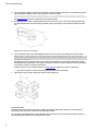
The branch part and NavAid appear at the selected point. You are prompted to pick a point indicating the direction of
the saddle end.
Please pick point : or [Center-offset<0>/Edge-offset/Flip-offset/Rotate90/World
plane/Initial plane/paRt plane/Align to
part/FOrward/AFt/Port/Starboard/Up/Down/plaNE/XRotate/YRotate/ZRotate/ SNap<on>]:
Optionally, enter one of the keywords:
•
Center-offset – To set an offset between the end axis of the branch part and the centerline of the header part
(the current offset is shown in <angle brackets>), type C (for Center-offset) and press Enter. Type an offset value
and press Enter.
•
Edge-offset – To set an offset between the edge of the branch part’s profile and the edge of the header part’s
profile (the current offset is shown in <angle brackets>), type E (for Edge-offset) and press Enter. Type an offset
value and press Enter. This option is only available when the header part has a consistent profile in the area
local to the saddle end.
•
Flip-offset – To reverse the direction of the current center or edge offset, type FL (for FLip-offset).
•
Rotate90 – To rotate the branch part about its own end axis by 90 degrees, type R (for Rotate90).
•
World plane – To align the NavAid to the world coordinate axes, type W (for World plane) and press Enter.
•
Initial plane – To align the NavAid to the UCS that was current when the command started, type I (for Initial
plane) and press Enter.
•
Part plane – To align the NavAid to the plane the header part lines in and the direction of its centerline closest
to the saddle end, type RT (for paRT plane) and press Enter.
•
Align to part – To rotate the NavAid within its own plane so that its zero angle is aligned with the nearest point
on the header part’s center line, type A (for Align to part) and press Enter.
•
Forward – To set the direction of the orienting end as close as possible to forward, type F (for Forward) and press
Enter.
•
Aft – To set the direction of the orienting end as close as possible to aft, type A (for Aft) and press Enter.
•
Port – To set the direction of the orienting end as close as possible to port, type P (for Port) and press Enter.
•
Starboard – To set the direction of the orienting end as close as possible to starboard, type S (for Starboard) and
press Enter.
•
Up – To set the direction of the orienting end as close as possible to up, type U (for Up) and press Enter.
•
Down – To set the direction of the orienting end as close as possible to down, type D (for Down) and press Enter.
•
Snap – To turn on or off snapping of picked points to fixed angles (the current setting is displayed in the
command line in <angle brackets>), type SN (for SNap) and press Enter.
11