1
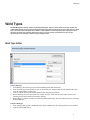
Weld Management
www.ShipConstructor.com
© Copyright 2012 ShipConstructor Software Inc. – Jan. 31, 13
ShipConstructor 2012 Weld Management
Published 2013-01-31
Copyright
Copyright © 2012 ShipConstructor Software Inc.
Information in this ShipConstructor manual is the property of ShipConstructor Software Inc. No part of it can be reproduced, translated,
resold, rented, adapted, modified, stored in a retrieval system or transmitted in any form or by any means, in whole or in part. All Rights
Reserved.
Trademarks
ShipConstructor
AutoMagic
SmartParts
Database Driven Relational Object Model
DDROM
Are all registered trademarks of ShipConstructor Software Inc.
ShipConstructor Software Inc.
Suite 304
3960 Quadra Street
Victoria, BC
Canada V8X 4A3
Toll Free:
Phone:
Fax:
1-888-210-7420
1-250-479-3638
1-250-479-0868
Information:
Support:
Sales:
[email protected]
[email protected]
[email protected]
Website:
www.ShipConstructor.com
SHIPCONSTRUCTOR LICENSE AGREEMENT
BEFORE PROCEEDING WITH THE INSTALLATION, YOU MUST ACCEPT THE TERMS OF THIS
AGREEMENT. INDICATE YOUR ACCEPTANCE OR REJECTION OF THIS AGREEMENT BY CLICKING ON THE
APPROPRIATE BUTTON. IF YOU CLICK ON “REJECT,” INSTALLATION WILL ABORT.
1. License Grant. ShipConstructor Software Inc., #304 – 3960 Quadra Street,
Victoria, B.C. Canada, V8X 4A3 (“SSI”) grants to the person accepting this
Agreement (the “Licensee”) a non-exclusive, non-transferable right to use (the
“License”) in object code form those program modules, application programming
interface (“API”), any other materials provided by SSI under this Agreement, and all
upgrades, revisions, fixes, updates or enhancements to any of the foregoing
(“Licensed Materials”) specified in the Licensee’s purchase order or request
(“Invoice) solely on the software and hardware listed in the Licensed Materials
manual (“System Configuration”).
2. Academic Institutions/Trial Versions.
A. In the event that the Licensee qualifies as an academic institution user in
accordance with SSI’s specifications (an “Academic Licensee”), the Academic
Licensee and its faculty, employees and students may use the Licensed Materials
for the singular purpose of either teaching, training users or undertaking
research provided that the Licensed Materials, and all copies of the Licensed
Materials, remain at all times at the Academic Licensee’s premises and the
Licensed Materials are used for no other purpose than that set forth above. The
above restrictions are in addition to the restrictions on use set out in Section 5
below.
B. In the event that the Licensee receives a trial version of the Licensed Materials
for evaluation purposes, the terms and conditions of this Agreement, excluding
Sections 15-19, shall continue to apply subject to the following provisions:
(a)
the License pursuant to Section 1 above shall terminate at the end of
the specified trial period;
(b)
the Licensee shall return the Hardware Key to SSI immediately upon
expiry of the specified trial period and in any event within 28 days of
the expiry of the specified trial period;
(c)
in the event that the Licensee does not return the Hardware Key in
accordance with Section 2B.(b) above, SSI shall be entitled to invoice
the Licensee for and the Licensee shall pay for the costs of the
Hardware Key plus all shipping and handling expenses and SSI
administrative charges; and
(d)
in the event that the Licensee elects to and does acquire a License, the
terms and conditions of this Agreement, excluding Section 2B herein,
shall continue on and apply.
3. Ownership. All rights, title and interests in and to the Licensed Materials and related
documentation shall remain the sole property of SSI. Licensee shall not remove or
alter any proprietary rights notices on the Licensed Materials and the
documentation, and shall reproduce such notices on any copies that it makes.
Licensee shall be liable for the security of the Licensed Materials and the
documentation in its possession.
4. Expertise Required. Licensee is responsible for evaluating whether the Licensed
Materials meets Licensee’s requirements, and for operating the Licensed Materials
and the results obtained. The Licensed Materials are intended for ship modeling and
construction purposes only, and must be used by a person who has expertise and
knowledge in this field. The Licensed Materials requires independent confirmation of
the reliability and accuracy of all designs, drawings and other Licensed Materials
output. An SSI representative may be made available under a separate consulting
agreement, at the Licensee’s request to provide training and consultation on the
operation or integration of licensed materials.
5. Limitations on Use.
Licensee shall:
(a)
not make more copies of the Licensed Materials than are necessary for the
Licensee’s installation of the Licensed Materials and shall only create
backup copies for archival or emergency restart purposes;
(b)
maintain a log of the number of and location of all originals and copies of
the Licensed Materials;
(c)
include SSI’s copyright, trademark and proprietary notices on any
complete or partial copies of the Licensed Materials in the same form and
location as the notice on any original work;
(d)
not attempt to defeat any copy protection;
(e)
not modify, any documentation, including any user manuals;
(f)
not modify, translate, reverse engineer, decompile or disassemble the
Licensed Materials;
(g)
not sublicense, transfer, assign, sell, loan, rent or lease the Licensed
Materials other than as permitted in this Agreement;
(h)
use the Licensed Materials for its own internal use only;
(i)
not permit any third party to use the Licensed Materials; and
(j)
thoroughly test any and all custom interfaces in accordance with general
engineering principles.
6. Delivery and Installation. All Licensed Materials will be delivered in an electronic
format by media or method as SSI may elect and will be sent to the Licensee’s
designated email address or shipping address as specified in the Invoice. Licensee
agrees to be responsible for installation of the Licensed Materials.
7. Term of License. The License term commences on the delivery of the Licensed
Materials to the Licensee, and, subject to Section 2B above, is either perpetual if so
requested on the Order, or on a month to month rental or lease basis. If Licensee
chooses a lease option the license converts to a perpetual term on Licensee’s
payment of the balance of the perpetual License fee (prior monthly payments
receiving 80% credit). All Licenses are subject to termination in accordance with
this Agreement.
8. System Configuration. Operation of the Licensed Materials requires use of the
specified System Configuration, which Licensee shall acquire and implement. SSI
shall not be responsible for any operational problems caused by the System
Configuration.
9. Security. The Licensed Materials includes security elements which support the
detection of unauthorized use or copying of the software and which may (a)report
such unauthorized use or copying to the Licensee, and (b)if applicable based on
Licensee’s configuration, may report back specific user information such as User
name and email address.
10.Hardware Keys. Licensed Materials use requires “Hardware Keys” supplied by SSI,
which can be used only at the site(s) authorized by SSI. In the event of a failure of
the Licensee’s System Configuration, the Licensee may upon advising SSI use the
Hardware Keys and Licensed Materials on another system and/or location.
11.License Fees. Licensee shall pay to SSI the License fees applicable for the Licensed
Materials as set out in and in accordance with SSI’s Invoice.
12.Services. Support services after the Warranty Period (as defined in Section 15
below) are provided by SSI under the terms of the SSI Subscription Agreement.
Installation, consulting, training and implementation services, if requested by the
Licensee, shall be provided by separate agreement and at an additional charge.
13.Taxes. All amounts payable by Licensee to SSI are exclusive of all commodity taxes,
including but not limited to applicable sales, use, value added, custom duties, excise
taxes and other similar government charges, all of which will be paid by Licensee. If
Licensee is required by law to withhold any taxes, then Licensee shall pay SSI a
gross amount of money such that the net amount received by SSI after deducting or
withholding the required taxes is equal to the amount of the fee originally charged
by SSI.
14.Interest Charges. If any amount payable under this Agreement is not paid within 30
days of becoming due, SSI shall have the right to impose a charge of 2% per month
(24% annually) on the unpaid balance of the amount, from the due date until the
date of receipt of all amounts in arrears including interest.
15.Purchase Orders. Any purchase order (an “Order”) delivered by Licensee shall at
all times be deemed to incorporate this Agreement by reference and shall be subject
to the applicable provisions of this Agreement. Any provisions of an Order shall not
apply and shall not be binding upon SSI unless they relate to information which was
requested by SSI. In the event of a conflict or an inconsistency between the
provisions of an Order and the terms and conditions of this Agreement, this
Agreement shall govern and supersede to the extent of such conflict or
inconsistency.
16.Limited Warranty. SSI warrants that during a period of 90 days from the date of
delivery of the Licensed Materials to Licensee (the “Warranty Period”), the
Licensed Materials will perform substantially in accordance with the Licensed
Materials documentation specifications, when used in accordance with this
Agreement on a properly operating System Configuration. SSI’s sole obligation
under this Warranty, and Licensee’s exclusive remedy, shall be to use reasonable
commercial efforts to correct Errors (a bug, defect or other problem incurred by a
user in operating the Software that prevents the Software from performing in a
manner consistent with the applicable specifications set out in the User Manual) that
the Licensee identifies to SSI through fixes or workarounds free of charge. If SSI
determines that it is unable to make the Licensed Materials perform substantially as
warranted, Licensee may terminate the License and receive a refund of a portion of the
License Fees paid to date.
17. WARRANTY EXCLUSIONS. THE LIMITED WARRANTY CONTAINED IN SECTION 15 IS
IN LIEU OF ALL OTHER WARRANTIES, EXPRESS OR IMPLIED. ALL OTHER
CONDITIONS, WARRANTIES, AND REPRESENTATIONS, EITHER EXPRESS OR
IMPLIED, ARE EXCLUDED, INCLUDING BUT NOT LIMITED TO CONDITIONS,
REPRESENTATIONS AND WARRANTIES RELATING TO MERCHANTABILITY AND
FITNESS FOR A PARTICULAR PURPOSE. SSI DOES NOT WARRANT THAT THE
LICENSED MATERIALS ARE COMPLETELY ERROR FREE OR THAT ITS OPERATION WILL
BE CONTINUOUS AND UNINTERRUPTED.
18.Maintenance Services. Licensee may elect, to obtain maintenance, support and
upgrade services from SSI in accordance with and subject to the terms of SSI’s
standard Subscription Agreement.
19.Loss of Data. SSI shall not be responsible for any loss of or damage to files or data
caused by the Licensed Materials, or be required to restore or rebuild files or data.
Licensee shall implementing adequate backup procedures to avoid any loss of files
and data.
20. Modifications. SSI may, from time to time, provide the Licensee with revisions to
the Licensed Materials (the “Revised Licensed Materials”). The Licensee shall test
any external applications using the revised API before implementing the new
version. While it is SSI’s intention that the Revised Licensed Materials shall be
backward-compatible with the immediately prior version of the Licensed Materials,
SSI does not guarantee or warrant that this shall be so, and SSI shall have no
liability whatsoever to the Licensee for any failure of the Revised Licensed Materials
to be backward compatible with any prior version of the Licensed Materials.
Modifications requested by the Licensee shall be subject to prior written agreement
as to scope and fees payable. Ownership of all Licensed Materials modifications
shall vest in SSI. SSI does not warrant, guarantee or otherwise commit to
supporting Licensed Materials that has been superseded by Revised Licensed
Materials.
21.Confidential Information. Each party will not use the confidential information of the
other party for any purpose except for the purpose described in this Agreement, and
shall not disclose it to any other person except on a confidential basis to its
employees and representatives who have a need-to-know the confidential
information for such purposes. This Section 23 shall not apply to confidential
information which (a) is or has become readily available to the public in the same
form other than by an act or omission of the receiving party, (b) was lawfully
obtained in the same form by the receiving party from a third party not under an
obligation of confidence to the disclosing party, (c) was in the receiving party’s
possession in the same and material form prior to its receipt from the disclosing
party and did not otherwise originate from the disclosing party, or (d) is required to
be disclosed by operation of law.
22. Audit Rights. Upon reasonable notice by SSI, which shall be delivered on no more
than an (annual?) basis, Licensee shall provide a signed statement verifying its
compliance with the terms of this Agreement. SSI shall also have the right, upon
reasonable notice and no more than on an annual basis, to inspect Licensee’s
facilities to verify Licensee’s compliance with such terms. Any such inspection or
audit shall be conducted either by SSI or by representatives authorized by SSI to
complete the inspection. If such inspections or audits disclose that the Licensee has
installed, accessed or permitted access to the Licensed Materials in a manner that is
not permitted under this Agreement, then Licensee shall be liable to pay for any
unpaid license fees as well as the reasonable costs of the audit.
23.Termination. This Agreement may be terminated by either party, immediately by
written notice, if the other party commits a breach of any material provision of this
Agreement, including a failure to make payment when due, and fails to correct or
rectify such breach within 30 days of receipt of the notice requesting it to do so.
SSI shall be entitled to place time-lock devices and other disabling features in the
Licensed Materials that become effective in the event that the Licensee has failed to
comply with its payment obligations hereunder and as set out in SSI Invoices.
24.Effect of Termination.
Upon termination of this Agreement Licensee shall
immediately cease using the Licensed Materials, and within 14 days of termination
return all Hardware Keys to SSI.
25.CONSEQUENTIAL DAMAGES. IN NO EVENT SHALL SSI BE LIABLE FOR ANY LOSS
OF DATA OR PROFITS, ECONOMIC LOSS OR SPECIAL, INDIRECT, INCIDENTAL,
CONSEQUENTIAL OR PUNITIVE DAMAGES WITH RESPECT TO THIS AGREEMENT
OR THE LICENSED MATERIALS, HOWEVER CAUSED, EVEN IF SSI HAD OR SHOULD
HAVE HAD ANY KNOWLEDGE OF THE POSSIBILITY OF SUCH DAMAGES.
26.DAMAGES LIMITATION. THE MAXIMUM LIABILITY OF SSI FOR ALL CLAIMS AND
DAMAGES OF ANY KIND, WHETHER FOR FUNDAMENTAL BREACH OR ANY OTHER
CAUSE UNDER THIS AGREEMENT, SHALL BE LIMITED IN THE AGGREGATE TO THE
TOTAL OF ALL FEES PAID BY LICENSEE.
27.LIMITATION OF NON-APPLICABILITY. IN SOME JURISDICTIONS THE EXCLUSION
OR LIMITATION OF WARRANTIES OR LIABILITY MAY NOT BE APPLICABLE, AND IN
SUCH JURISDICTIONS SSI HEREBY LIMITS ITS LIABILITY TO THE FULLEST EXTENT
PERMITTED BY LAW.
28.Applicable Law. This Agreement shall be subject to and construed in accordance
with the laws of the Province of British Columbia, Canada, excluding its conflict of
laws rules and the application of the UN Convention on Contracts for the
International Sale of Goods.
29.References. SSI shall be allowed to incorporate Licensee’s name in SSI’s customer
reference list and to use it for marketing.
30.Dispute. If any dispute arises under this Agreement, a good faith attempt to resolve
the dispute will be made by senior management of both parties at a mutually
agreeable site and time. If the parties are unable to reach agreement within 30
days after a request for such meeting, the dispute shall be referred to arbitration in
English, before one arbitrator in Victoria, British Columbia, Canada, in accordance
with the Commercial Arbitration Act of the British Columbia.
31.Entire Agreement. This Agreement contains the entire agreement between the
parties and shall supersede all prior discussions and agreements between the parties
regarding its subject matter.
32.Amendment. Any amendment of this Agreement must be in writing and signed by
duly authorized representatives of the parties.
33.Waiver. The waiver by any party of a breach by the other party of this Agreement
shall not be construed as a waiver by such party of any succeeding breach by the
other party of the same or another provision.
34.Assignments. Licensee may not assign or transfer the License or Licensee’s rights or
obligations under this Agreement without SSI’s prior written consent, and any such
assignment or transfer without consent shall be null and void. A transfer of all or
substantially all of the voting stock of the Licensee shall constitute a transfer for
these purposes and shall be subject to SSI’s prior written consent.
35.Successors and Assigns. This Agreement will bind and enure to the benefit of the
parties and their respective successors and permitted assigns.
36.Severability. In the event that any provision of this Agreement is declared invalid,
illegal or unenforceable by a court having jurisdiction, then the remaining provisions
shall continue in full force and effect.
37.Force Majeure. Except as related to Licensee’s obligation to make payments to SSI,
neither party shall be liable for delays or non-performance if such delays or nonperformance are beyond such party's reasonable control. A delayed party shall
promptly notify the other party in writing stating the cause of the delay and its
expected duration and shall use commercially reasonable efforts to remedy a delay
or non-performance as soon as reasonably possible.
38.Survival. The provisions of Sections 3, 5, 11, 13, 14, 17 and 20-30 shall survive the
expiry or termination of this Agreement.
39.Language. It is the express will of the parties that this Agreement and related
documents have been prepared in English. C’est la volonté expresse des parties que
la présente Convention ainsi que les documents qui s’y rattachent soient rédiges en
anglais.
#363338
28/05/2010
Contents
Contents
Weld Types
1
Weld Type Editor................................................................................................................................................... 1
Usage Logs.................................................................................................................................................................................2
Weld Standards
2
Weld Standard Editor........................................................................................................................................... 3
Weld Schedule
Weld Management Drawings
6
11
Update Weld Drawings......................................................................................................................................12
Identifying Drawings that Require Updating ..................................................................................................................... 12
Updating an Existing Weld Management Drawing........................................................................................................... 13
Weld Manager
14
Index
19
i
Weld Types
Weld Types
The Weld Management module contains 18 predefined weld types. Types may not be added or removed, however the
symbol representations of these types are fully customizable. Each weld type represents the type of weld done on a single
pass of the welder. These weld types will be added to a weld standard in a later stage in the form of processes. Those
processes will contain the properties defined in this stage, and can be further customized later on. The symbol
representation of the weld type is defined using the weld type editor.
Weld Type Editor
Note: The Weld Type Editor is now an AutoCAD palette. It can be docked, or rolled up in AutoCAD. This can be very
useful when trying to model the weld type.
To Edit a Weld Type
1.
2.
3.
4.
5.
From Manager, select Weld Types from the Weld Management pull-down menu.
Select the weld type whose symbol you wish to edit from the list, and then click the Edit Symbol button. This
opens the editor window in AutoCAD.
Create or edit the desired symbol using standard AutoCAD geometry elements.
Before inserting a keyword, specify the size, rotation, and style. Then click the Insert button, and select the
insertion point for the selected keyword in the drawing.
When editing is complete, click the Close Drawing button in the dialog. This will return focus to the weld types
dialog in Manager.
To Export a Weld Type
1.
2.
In the weld type dialog, place a checkmark in the export column next to all weld types that are to be exported.
Click the Export XML button.
1
Weld Standards
3.
Name the XML file and choose a directory to save it to, then click the Save button.
To Import a Weld Type
1.
2.
3.
Click the Import XML button from the weld type dialog.
When prompted, select the XML file which contains the weld types to be imported.
The XML file may define multiple weld types. Place a checkmark next to the types to be imported and click the
OK button.
Note: Imported weld types are not saved to the database until the weld types dialog is closed by the user via the
OK button.
Usage Logs
Usage logs are a convenient way to quickly see which weld standards implement a given weld type. This is useful,
since any changes made to that weld type will affect all of those standards.
To Create a Weld Type Usage Log
1.
2.
Select a weld type from the list in the weld types dialog.
Click the Usage Log button. This will generate a usage log for that weld type in a text file.
Weld Standards
Once the weld types have been defined, it is time to define weld standards. Each weld in a project will have a weld
standard assigned to it so that the welder knows what types of welds to apply to a given join, how many passes are
required, and any other details.
2
Weld Standards
A weld standard is made up of one or more weld processes, where each process is of one of the types defined in the
previous stage. The order that processes are added to the standard is the same order that each process will be applied to
the weld, although this order can be modified after all processes are added to the standard. Once all desired processes
have been added to the standard, the standard symbol can be further customized.
Weld Standard Editor
To Create a new Weld Standard
1.
2.
3.
4.
5.
Open the weld standards dialog by selecting Weld Standards from the Weld Management pull-down menu.
Click the New button. This will create a new weld standard with default properties and no processes or tail
notes applied.
Give the new standard a unique name and edit the material and model color by clicking on the appropriate cells
on the grid. You can also add notes which will appear behind the tail of the weld symbol. Be sure to assign the
tail notes size a value greater than 0, or the notes will not be visible on the symbol.
You can now add weld processes to the standard. Select a type from the Types pull down menu, and then click
the Add button. This will cause a process editor dialog to appear. The editable properties in this dialog vary
depending on the weld type it describes. Once the desired properties have been entered, push the OK button.
This will create a new row in the process list for the selected weld standard. Processes for other weld standards
can be viewed by selecting those standards in the upper table.
3
Weld Standards
To Edit a Weld Process
1.
2.
3.
Select the weld standard with processes to be edited from the upper table.
Select the process to be edited in the lower table and click Properties…
The same dialog that was presented when the process was created will appear. Edit properties as desired and
then click OK.
To Delete a Weld Process
1.
2.
Select the weld standard with processes to be deleted from the upper table
Select the process to be deleted in the lower table and click Remove.
Altering the Process Order
The order that weld processes appear in the lower table represents the sequence in which they are applied to the weld.
Processes at the top of the list are applied first, and those at the bottom are applied last. To change the order of this list,
click on a weld process and click the Up or Down button.
To Export a Weld Standard
1.
2.
3.
In the weld standards dialog, place a checkmark in the export column next to all weld standards that are to be
exported.
Click the Export XML button.
Name the XML file and choose a directory to save it to, then click the Save button.
To Import a Weld Standard
1.
2.
3.
4
Click the Import XML button from the weld standards dialog.
When prompted, select the XML file which contains the weld standards to be imported.
The XML file may define multiple weld standards. Place a checkmark next to the standards to be imported and
click the OK button.
Weld Standards
Note: Imported weld standards are not saved to the database until the weld standards dialog is closed by the
user via the OK button.
To Copy a Weld Standard
1.
2.
Click on the weld standard to be copied in the upper table in the weld standards dialog.
Click the Copy button. This will create a new weld standard with all the same properties of the original standard
and add it to the list.
To Edit the Weld Standard Symbol
Note: The Weld Standard Symbol Editor is now an AutoCAD palette. It can be docked, or rolled up in AutoCAD. This
can be very useful when trying to model the symbol.
1.
2.
3.
4.
Select the weld standard whose symbol you wish to edit from the list, and then click the Edit Symbol button.
This opens the editor window in AutoCAD.
Symbols defined for individual weld processes can be dragged as a unit which includes all geometry and
keywords defined for that weld type.
Create or edit any custom geometry using standard AutoCAD geometry elements.
Before inserting a keyword, specify the size, rotation, and style. Then click the Insert button, and select the
insertion point for the selected keyword in the drawing.
Note: Keywords can only be inserted if they were assigned a value in the weld process Properties dialog.
5.
6.
Create or edit any custom text using AutoCAD Text or MText.
When editing is complete, click the Close Drawing button in the dialog. This will return focus to the weld
standards dialog in Manager.
To Reset a Standard Symbol
A weld standard symbol can be returned to its default appearance by selecting that standard from the upper list and then
clicking the Reset Symbol button. This will return the symbol to the appearance it had when it was first created. This
means that all custom geometry and text will be removed and all process symbols will be moved back to their default
locations. Also, any deleted processes will be brought back.
5
Weld Schedule
Usage Logs
The weld standards usage log is used to instantly reference which scenarios and welds utilize a given standard. This
allows the user to quickly view which welds will be affected by a change to that standard. The usage log for a given
standard can be viewed by selecting that weld standard in the upper table, and then clicking the Usage Log button. This
will generate a usage log for that weld standard in a new text file.
Weld Schedule
The weld schedule is used to organize weld standards into particular scenarios where they will be used. Each row in the
schedule represents a scenario in the project. These scenarios consist of a physical location on the ship, as well as two
types of parts to be welded together. Each of these scenarios is further subdivided by the minimum thickness columns,
which represent the thickness of the smaller part to be welded. Multiple welds may be applied to each thickness, and a
single weld standard may be applied to multiple scenarios and thicknesses.
To Create a New Scenario
1.
2.
3.
4.
5.
Open the weld schedules dialog by selecting Weld Schedules from the weld management pull-down menu.
Click the New button.
This will create a new scenario and add it to the bottom row of the table. The Location, Attached Member, and
Attached To Member fields will all be filled with default values.
On the newly added scenario, click on the cell in the Location column. From the pull-down list that appears,
select the location on the ship that this scenario pertains to.
Repeat step 4 for the Attached Member and Attached To Member columns, selecting appropriate part types for
each.
Note: The Location, Attached Member, and Attached To Member values can be edited at any time by following
steps 4 and 5.
6
Weld Schedule
To Create a New Location
1.
2.
Click the Locations button in the weld schedules dialog.
The Edit Weld schedule Locations dialog will appear. Click New in this dialog.
3.
4.
5.
A new row in the Locations list will be created with a default name. Click on the row to rename the location.
Repeat steps 2 and 3 for however many new locations are desired.
To remove a location, select it in the list and click the Delete button.
Note: If the location to be deleted is currently in use in a schedule, a warning message will appear to inform the
user of which scenarios are using that location.
6.
Click OK to close this dialog.
Note: The newly created locations will be immediately available in the location pull-down menus, for use in
scenario editing or creation.
To Create a New Member
1.
Click the Members button in the weld schedules dialog.
7
Weld Schedule
2.
3.
4.
5.
The Editing Weld Schedule Members dialog will appear. Click New in this dialog.
A new row in the Members list will be created with a default name. Click on the row to rename the member.
Repeat steps 2 and 3 for as many new members are required.
To remove a member, select it in the list and click the Delete button.
Note: If the member to be deleted is currently in use in a schedule, a warning message will appear to inform the
user of which scenarios are using that member.
6.
Click OK to close this dialog.
Note: The newly created members will be immediately available in the Attached Member and Attached To
Member pull-down menus, for use in scenario editing or creation.
To Create a New Thickness Column
1.
2.
3.
4.
Click the Sizes button in the weld schedules dialog.
Following the same steps as for locations and members, create or delete new minimum thickness values in the
table presented in the Editing Weld Schedule Minimum Thickness dialog.
Click OK when finished.
New columns will appear in the schedule, corresponding to the new values entered.
To Assign Weld Standards
Whenever the weld schedules dialog is open, there will be a second box displaying all created weld standards present.
This box allows the user to view and edit which standards are used in each scenario.
1.
2.
8
Click on a cell in the weld schedule in one of the thickness columns.
That cell contains the names of any weld standards used in that scenario for that minimum thickness. The weld
standards box will show a checkmark next to each standard that is included.
Weld Schedule
3.
4.
To add a standard to the selected scenario and thickness, place a checkmark next to the desired standard in the
Used column of the weld standards box.
To remove a standard from a given scenario, remove the corresponding checkmark from the standards box.
Note: Weld standards may be applied to several scenarios simultaneously by group-selecting several cells in the
weld schedule and then placing a checkmark next to the desired standard as in step 3.
Replacing Weld Standards
If there is a situation in which several instances of a certain weld standard need to be replaced with another standard,
this can be done in a single operation. This avoids the tedious task of selecting each scenario individually, deleting the
existing standard, and adding the replacement.
1. In the weld schedule, group-select all cells containing the standard to be swapped out.
2. Click the Replace Standards button.
3. The Replace a Weld Standard dialog will appear. In this dialog, the list on the left represents all standards
present in the user’s selected cells. The list on the right represents all existing weld standards (with the currently
selected standard from the left list removed).
9
Weld Schedule
4. Select the standard to be removed in the left list, and the desired replacement standard in the right list, then click
Replace.
5. Repeat step 4 for any other standards to be replaced.
6. Click the Close button.
Using Row Filters
Row filters can be used to simplify the weld schedule when working with large amounts of data. The Location, Attached
Member and Attached To Member columns each have a user-editable filter at the top of each column. Since the data in
the Attached Member and Attached To Member are interchangeable, a filter applied to one column will apply to both.
10
Weld Management Drawings
Filters can be cleared by clicking the x in the filter cell, or all applied filters can be removed at once by clicking the Clear
Filters button.
Weld Management Drawings
A weld management drawing gives a view of a selected assembly or group of assemblies to give a visual representation
of generated welds. It is only in a weld management drawing that the Weld Manager, which is used for the creation,
deletion and modification of welds and part connections, may be accessed.
Creating a Weld Management Drawing
1.
Choose ShipConstructor > Navigator to open Navigator.
2.
Select Weld Management in the component list.
3.
Click the New button.
4.
Enter a name for the Weld Management drawing and click OK.
5.
A view of the current Product Hierarchy tree is shown. Select all assemblies that are to be loaded into the weld
management drawing.
Note: Parts and assemblies may be unloaded or unloaded from the drawing at any time from the Weld Manager, so
the assemblies selected at this step can be changed if needed.
Note: Parts and assemblies need not be loaded into the weld drawing in order to have welds generated for them. If
welds are to be generated for a large assembly or a complete unit, it is recommended that fewer parts be loaded
into the drawing, as weld generation can be a memory-intensive process. So the fewer loaded parts there are, the
11
Weld Management Drawings
better the weld generation performance. Parts may be loaded after the weld generation is complete for visualization
purposes.
6.
The Weld Management Drawing will open automatically, with all selected parts loaded.
Update Weld Drawings
ShipConstructor weld management drawings can be updated. Drawings that need updating can easily be identified in
Navigator.
Identifying Drawings that Require Updating
Weld management drawings that required updating because the parts contained in the weld management drawing have
changed are identified in Navigator.
To identify out-of-date weld management drawings
1.
Choose ShipConstructor > Navigator to open Navigator.
2.
Select Weld Management in the component list.
3.
Click the Show Out of Date button.
Out of date weld management drawings can be identified by the exclamation mark icon
(
12
Weld Management Drawings
)
Updating an Existing Weld Management Drawing
Weld management drawings that are out of date can be updated instead of re-created. This lets you preserve all the
customization work done on a weld management drawing, as only the modified geometry of the parts is modified.
To update a weld management drawing
1.
Choose SC Weld Management > Update Drawing to start updating the drawing.
2.
ShipConstructor determines all parts that need to be updated.
3.
The Modified Part Information window appears.
4.
You can use the Modified Part Information window to inspect parts that have changed during this update.
5.
Click OK to finish the drawing updating.
13
Weld Manager
Weld Manager
The Weld Manager is the main control center for creating and modifying all welds in a project. The Weld Manager is only
accessible while in a Weld Management drawing. It can be used to generate welds for any assemblies within the current
unit, whether they are loaded into the Weld Management drawing or not.
The Weld Manager is opened by clicking on the Weld Manager icon, or by typing SCWELDMAN at the command prompt,
while in a Weld Management drawing.
The left-most panel of the Weld Manager contains a product hierarchy tree with limited functionality. Parts can be loaded
or unloaded from the drawing using this tree, and parts that are selected in the tree will be automatically selected in the
drawing and vice versa. Parts that are loaded in the current weld management drawing will appear with a lit bulb next to
them, and all parts that are not loaded will appear with a grey bulb. Drag and drop functionality for reassigning parts to
new assemblies is disabled in the weld manager, and new assemblies may not be created, nor can assemblies be
removed.
The top-right panel shows the connections list. Connections between parts are generated when welds are generated for
the first time. Connections between parts will be displayed in this panel when their parent assembly is selected in the
product hierarchy tree. Connections may also exist between two assemblies, or between a part and an assembly.
14
Weld Manager
The bottom-right panel shows the welds list. This is where standards can be assigned to generated welds. Welds are
always assigned to a connection, so to view a specific weld the desired connection must be selected in the connections
list. This will display all of the welds assigned to that connection in the welds list.
Generating Welds for an Assembly
1.
In the product hierarchy tree, select the assembly which is to have welds generated for it.
2.
Click the right mouse button, and select Generate Welds from the popup menu.
3.
The Weld Manager state must be saved at this point, so select yes when prompted to save.
Note: Since weld generation can be a long process, there is a chance that the operation could be interrupted before
it has a chance to complete. If this happens, the welds that were generated before the interruption will be saved and
do not need to be generated again. Instead, follow the same instructions as above, but in step 2 select Continue
Generating Welds from the popup menu. This will continue the generation operation from where it left off the first
time.
4.
Once complete, select the assembly to view all of the generated connections between parts or assemblies at this
level. Click on any sub-assemblies to view connections at those levels as well. The connections should display the
parts or assemblies involved, as well as the status of the connection.
5.
Click on a connection in the connections list to view welds that are assigned to that connection. Connections
between two parts should have a single weld assigned to them by default. Connections between assemblies may
have multiple welds assigned to them, since there may be multiple points of contact between parts in those
assemblies.
Generating Welds between Parts
The previous steps will generate welds between all parts within a selected assembly and its sub-assemblies. If only a
single weld is desired between two parts, or if welds are required only between two specific assemblies, this can be
accomplished as follows:
1. In the product hierarchy tree, select the first part or assembly to be welded, and then hold the ctrl key and select the
second part or assembly.
2. Click the right mouse button and select Generate Welds from the popup menu.
3. Follow steps 3 through 6 as for generating welds for an assembly.
15
Weld Manager
Creating a weld with a user-defined Weld Path
When welds are generated using the procedure described in the previous section, the weld path will be automatically
generated based on the overlapping sections of the two parts involved. However, if the user wants to specify the weld
path for a given weld, this can be done as follows
16
1.
Draw a Polyline or Curve along the path that you would like to define as the Weld Path. Multiple lines may be
associated with a single Weld.
2.
Click the “Assign Weld Path” button above the Connections table.
3.
At this point, you are prompted to select two parts in the drawing. Exactly two structure parts must be selected. After
they are selected, press the Enter key.
4.
Next, select the polylines or curves which are to make up the weld path and press the enter key.
5.
This process will generate a new weld with the defined weld path. This weld can be found in the weld table along
with all other generated welds. It is distinguished from the other welds by the checkmark in the User Defined column
of the welds table. Welds that are marked as User Defined will not be overwritten during a weld generation operation
on their parent assembly unless the user specifies that they are to be overwritten.
Weld Manager
Copying existing Welds
There may be situations where a single connection may have multiple welds assigned to it. For instance, two parts may
have multiple welds between them (a different type for each side, for example). Or, if a connection is between two
assemblies, then there may be multiple parts within those assemblies which require welds between them. In this case, a
weld for each part pair must be assigned.
If a connection between two parts or assemblies has already been generated, but additional welds are required on that
connection, this can be done as follows:
1.
Select the appropriate connection from the connections list. Then select the weld to be copied in the Welds Table
2.
Click the Copy Weld button above the Welds Table.
3.
A new weld will be created, which can be seen in the welds list as long as the current connection is selected. This
Weld will be marked as User Defined as described in the previous section.
Defining Weld Properties
Once a weld has been created, it is ready to be assigned a weld standard. This will determine which weld symbols will be
displayed in the assembly drawing, indicating the types of welds involved in that assembly. Other properties can also be
assigned at this step.
1.
Select a weld from the welds list.
2.
Open the Select Weld Standard window either by clicking on the Standard button, or by double-clicking on the Weld
Standard cell of the selected weld.
3.
The Select Weld Standard window looks just like the Weld Schedule created in Manager. Select the desired weld
standard from this table, paying attention to the scenario where the standard is located. The same standard may be
used in several scenarios, but not all of those scenarios may be appropriate for this particular weld.
4.
Click the OK button to close the Select Weld Standard window.
5.
The Weld Standard, as well as all scenario information (Location, Attached Members, Minimum Thickness) will be
filled in for this weld.
6.
Further properties such as Position, Status, and Approval Status can be set manually here.
17
Weld Manager
7.
Placing check marks in the All Around and Field Weld cells will modify the weld symbol appropriately to include
these indicators.
8.
Notes may be added to the Notes cell, if this weld requires any specific instructions.
Note: All of the above properties may alternatively be set by selecting a weld from the weld list, and then clicking the
Properties button. This brings up a dialog which may also be used to set the properties described in this section.
Setting properties in this dialog will give the same results as setting them as in the above steps.
Displaying Welded Parts
To simplify the visualization of a given weld, it is possible to hide all parts in the drawing that are not associated with that
weld.
1.
Select the desired weld in the welds list.
2.
Right-click on the weld in the list, and select Display Only Welded Parts from the popup menu. Alternatively, click the
Display Welded button while the desired weld is highlighted in the list.
3.
This will cause all parts in the drawing to become hidden, except for the two parts involved in the selected weld, and
the weld object that joins them.
4.
To restore all hidden parts, click the Display All button, or select Display All Parts from the right-click menu.
Viewing the Weld Paths
Weld paths are generated during the weld generation step, however they are not made visible in the drawing
immediately. Welds for a given assembly can be viewed as follows:
18
1.
Select the desired assembly in the product hierarchy view. Welds will be displayed for all parts and sub-assemblies
belonging to this selected assembly.
2.
Right-click on the selected assembly in the product hierarchy and select Display Welds in Drawing from the popup
menu.
3.
The weld manager must be saved at this point, so click yes when prompted to save in order to continue.
4.
View the parts in the weld drawing. Weld path objects have been generated to represent welds between parts.
Index
Index
No index entries found.
19