1
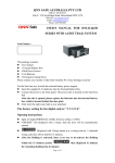
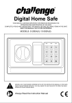
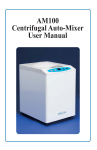
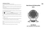
TST100 Static Transfer Switch USER MANUAL Version 1.0 Date : Nov 2009 TST100 user’s manual 1. Important Safety Instruction 1.1 Safety Instruction As dangerous voltages and high temperature exist within the equipment, only qualified and authorized maintenance personnel are permitted to open and repair it. This manual contains information concerning the installation and operation of the TST100。All relevant parts of the manual should be read prior to commencing the installation. Please follow the local stipulation meantime. Any operation against safety requirement or against design, manufacture, safety standard, and are out of the manufacturer warranty. 1.2 General Precaution 1.2.1 Do not expose to dust, rain, snow or liquids of any type,it is designed for indoor use. DO NOT block off ventilation, otherwise it would be overheating. 1.2.2 To avoid fire and electric shock, make sure all cables selected with right gauge and being connected well. Smaller diameter and broken cable are not allowed to use. TST100 user’s manual 2. Introduction 2.1 Introduction The TST100 Static Transfer Switch is single-phase transfer device, providing automatic switching between two independent AC power sources. It combined the STS and MTS into one unit which greatly increased the system reliability along reducing the transfer time to less than 4ms. It was suitable for important IT equipment which can not afford power disruption and ATS can not satisfy. 2.2 Feature z Transfer time less than 4ms when input power are synchronization and transfer time is less than 10ms in case of input non-synchronization\ z Intelligent monitor, diagnostics and alarming z Protection and alarm against High Voltage, Low Voltage, Power Failure and Overload. z Overload protection: STS shutdown in case of 150% overload and will reconnect after 10s z Shortcut protection: in case of output shortcut, system would cutout output offering protection for input power. z User can set up either input as main and the other will be standby automatically z Support manual select z In case of STS fail, the system will choose one input source as fix source, to ensure uninterruptible power supply z RS232 or RS485 communication z Structure : 19”2U TST100 user’s manual 2.3 Specification Model rated Amps Dimension Weight Input voltage Output voltage Input rated frequency Overload Capability transfer time Efficiency Transfer mode Peak factor Operation Temp Storage Temp Humidity Communication TST120 20A TST132 TST150 TST100 32A 50A 100A 19"2U (87x483x259mm -- HxWxD) 15kgs 17kgs 19kgs 22kgs 220±15% 220±15% 50Hz/60Hz 150% <4ms - synchronization <10ms - non-synchronization >99% Break before make .4:1 .-5C-40C .-25C-60C <93% non condensing RS485 + Dry contacts TST100 user’s manual 3.Principle and structure 3.1 Principle 3.2 Panel and Indicators 3.2.1 Front panel TST100 user’s manual LED 1 Syn Color Green Green Red Green Green Red 2 Input 1 3 Output 1 4 Output 5 Switch 6 Auto/Manual 7 Input 2 8 9 Output 2 Mute Green Red Green Status indicate input 1 and input 2 are in synchronization input 1 normal input 1 fault output using input 1 Output normal Output fault switching between input 1 and input 2 under MANUAL condition choose working mode. Under auto mode, input 1 will be named as priority automatically input 2 normal input 2 fault output using input 2 Mute the alarm 3.2.2 Rear panel No. 1 Dry contact 2 3 4 Circuit breaker Connector Connector Left 1 Left 2 Left 3 Left 4 Description Overload Input 1 fault Synchronization fault Input 2 fault Input 1 circuit breaker Input 1 – L Input 1 – N TST100 user’s manual 5 6 7 8 9 10 11 12 Connector Connector Connector Circuit breaker Connector Connector Connector Communication port 3.3 Structure Size Earth Input 2 – L Input 2 – N Input 2 circuit breaker Output – L Output – N Output – Earth RS485 TST100 user’s manual 4.Installation 4.1 Preparation Only a professional electrician is permitted to install the unit. 4.1.1 Inspection Before installation, unit should be unpack the package and check the package contents. Keep all spare part and accessories for future use. 4.1.2 Tool, Information Multi-meter、tool box、user manual、cable 4.1.3 Ambient Condition Environment requirements: z Working temperature:0-40℃ z Storage temperature:-40-70℃ z Relative Humidity:0%-95%,non-condensing z Cooling:forced air z Vertical angle:No vibration and hading angle less than 5 degree Working temperature of 20~25℃ and Humidity of 50% are recommended. Caution The STS must be installed in a location with good ventilation, far away from water, inflammable gas and corrosive agent. TST100 user’s manual 5.0 Operation 5.1 Power ON z Double confirm the input voltage matches the voltage of this equipment, do not connect different voltage otherwise it will damage the equipment z Check if wiring of input 1, input 2 and output are right z After above check and everything is right, please switch on the input 1 switch and input 2 switch 5.2 Operation 5.2.1 Switch Test z Set the auto/manual switch at manual, you can choose either input as main. z Set the auto/manual switch at auto, the input 1 will be chose as main. Switch off the input 1 and STS will switch to input 2. Then, close the input 1 switch, the STS will resume to input 1. z At auto position, you can not manually choose input 1 or input 2 5.2.2 Mute System offer alarm in case of fault, you could press mute button (for 3secs) in case of alarm. Unit 3, 30 Heathcote Rd Moorebank NSW 2170 Ph: 02-9602 8331 www.alphapower.com.au