1
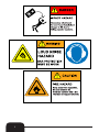
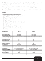
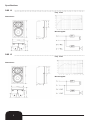
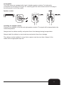
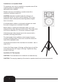
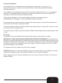
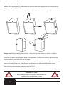
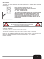
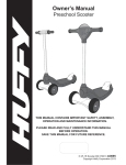
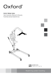
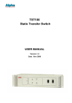
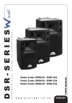
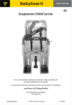
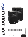
USER MANUAL
Order Code: SPEA38 - DSR 12
Order Code: SPEA39 - DSR 15
ENGLISH
WARNING
FOR YOUR OWN SAFETY, PLEASE READ THIS USER MANUAL CAREFULLY
BEFORE YOUR INITIAL START-UP!
Unpacking Instructions
Immediately upon receiving this product, carefully unpack the carton and check the contents to
ensure that all the parts are present, and have been received in good condition. Notify the dealer
immediately and retain the packaging material for inspection if any parts appear damaged from
shipping or the carton itself shows signs of mishandling. Save the carton and all packaging
materials. In the event that a fixture must be returned to the supplier, it is important that the fixture
is returned in the original carton and packaging.
CAUTION!
Keep this equipment away from rain,
moisture and liquids.
SAFETY INSTRUCTIONS
Every person involved with the installation, operation & maintenance of this
equipment should:
-
Be competent
-
Follow the instructions of this manual
Before your initial start-up, please make sure that there is no damage caused during
transportation. Should there be any, consult your dealer and do not use the equipment.
To maintain the equipment in good working condition and to ensure safe operation, it is necessary
for the user to follow the safety instructions and warning notes written in this manual.
Please note that damages caused by user modifications to this equipment are not
subject to warranty.
1
IMPORTANT:
The manufacturer will not accept liability for any resulting damages caused
by the non-observance of this manual or any unauthorised modification to the
equipment.
• Never leave any cables lying around.
• Do not insert any objects into the air vents.
• Never remove warning or informative labels from the equipment.
• Do not open the equipment and do not modify the equipment.
• Only use the equipment indoors.
• Do not expose to flammable sources, liquids or gases.
• Make sure you don’t use the wrong kind of cables or defective cables.
• Do not drive the inputs with a signal level bigger, than required to drive the equipment to its full output
• Prevent distortion! Make sure that all components connected to the speaker have
sufficient power ratings. Distortion will be generated if the components are operated
at their limits.
• The user is responsible for correct positioning and operating of this fixture. The
manufacturer will not accept liability for damages caused by the misuse or incorrect
installation of this equipment.
• Repairs and servicing must only be carried out by a qualified technician.
THIS UNIT CONTAINS NO USER SERVICEABLE PARTS.
• WARRANTY; One year from date of purchase.
2
3
The DSR series must always be provided with enough stability. The speaker(S) base surface must
always be sufficiently dimensioned in relation to the other speaker(s) in order to prevent the
cabinets tilting over.
Make sure that the area below the installation place is blocked when rigging, derigging or
servicing the system.
Please note: W Audio cannot be made liable for damages caused by incorrect installations and
excessive noise levels.
Features
• High impact molded polypropylene enclosure.
• 1.5” Voice Coil, 1 inch Exit Aluminium Compression Driver.
• 12” or 15” Mid-Low frequency transducers.
• 1” Compression high frequency driver.
• 80˚ x 60˚ Coverage pattern.
• 5 Integral suspension points.
• Complete mounting solutions.
• Smooth Response With High Power Handling Capacity.
• Ideal for entertainers, mobile discos and small bands.
• Constant directivity horn.
• Passive 2 way crossover.
• Balanced frequency range with high sound pressure levels.
• Very high durability.
• Speaker connection via lockable speaker plugs.
• Stand adaptor.
Specifications:
DSR 12
DSR 15
Freq. Range(-10dB):
50Hz~20kHz
40Hz~20kHz
Freq. Response(-3dB):
55Hz~18kHz
45Hz~18kHz
Rec. Hi pass Frequency:
30Hz
25Hz
Max Calculated SPL:
97dB
98dB
Horizontal Coverage:
80˚
80˚
Vertical Coverage:
60˚
60˚
200W RMS, 800W Peak
250W RMS, 1000W Peak
8Ω
8Ω
LF Transducer:
12”/304mm
15”/381mm
HF Transducer:
1”/25mm
1”/25mm
1.8kHz
2kHz
2 x 4-pole speaker sockets
2 x 4-pole speaker sockets
615 x 416 x 356mm
740 x 475 x 400mm
Net Weight:
19Kgs
22Kgs
Shipping Weight:
23Kgs
27Kgs
System Power:
Nominal Impedance:
Crossover Frequency:
Loop/Mix Out:
Dimensions (H×W×D):
4
Specifications:
DSR 12
Freq. chart:
Dimensions:
Block diagram:
DSR 15
Freq. chart:
Dimensions:
Block diagram:
5
Connections
This PSR series are equipped with 4 pole, lockable speaker sockets. For locking the
connection turn the plug to the right. For unlocking pull the unlock button and turn the plug to
the left and pull it out of the socket.
Speaker socket
Installing the speaker cables
Connect your amplifier to the left and right speaker sockets. The signal will be transmitted to the
individual speakers.
Always treat the cables carefully and protect them from damage during transportation.
Always install the cables in a structured way and protect them from damage.
The cables must be installed in a way that no person can trip over them. Always fix the
cables with an appropriate tape etc.
6
Installation on a Speaker Stand
The speakers may only be installed on a speaker stand if the
original speaker is equipped with an
appropriate stand adaptor.
Stands must only be installed on a plane area with a
maximum inclination angle of 5˚.
CAUTION: Speakers installed under the influence of
horizontal forces, e.g. wind, can be impaired. This is why
additional safety measures like attaching ballast weights
have to be taken.
If inclined tension cables or prolonged outriggers are used.
the area of danger has to marked or blocked.
Before lifting or lowering the telescopic tubes, you must
always block a safety area around the stand. This safety area
must have a diameter of 1.5 times the maximum height.
Lifted telescopic tubes always have to be secured with a
secondary securing attachment.
The total weight of the installation (total weight of system
including individual parts) must never exceed the maximum
load of the installation area.
Unintended movement of the load has to be avoided - also in
case of fire!
Loosen the fixing screws of the legs, pull the legs out until the
cross struts are at a 90˚ angle to the legs. Tighten the fixing
screws of the legs.
Installation Of The Speaker
CAUTION: The loads have to be installed in a balanced way.
CAUTION: The carrying capacity of the stand or speaker stand must never be exceeded.
7
Overhead Installation
If the speaker is to be installed with a mounting height of more than 1 meter (e.g. on a
stage or framework), the speaker must always be secured with an appropriate secondary
securing attachment.
The installation must always be secured with a secondary safety attachment. e.g. an appropriate
catch net. The secondary safety attachment must be constructed in a way that no part of the
installation can fall down if the main attachment fails.
When rigging, derigging, or servicing the speaker standing in the area below the
installation place, on bridges or other endangered areas are forbidden.
The operator has to make sure that the safety data is approved by an expert before operation for
the first time and after any changes are made.
The operator has to make sure that the safety data is approved by an expert after every four years
in the course of an acceptance test.
The operator has to make sure that the safety installation data is approved by a skilled person once
a year.
Procedure
The speaker should be installed outside areas where persons may walk by or seated.
IMPORTANT! OVER HEAD RIGGING REQUIRES EXTENSIVE EXPERIENCE, including (but not
limited to) calculating working limits, installation materials used, and periodic safety inspection of all
installation materials and the speaker. If you lack these qualifications, do not attempt the installation
yourself, but instead use a professional structural rigger. Improper installation can result in bodily
injury and damage to your property.
The speaker has to be installed out of the reach of people.
CAUTION: Speakers in overhead installations may cause severe injuries when falling! If you have
doubts concerning the safety of a possible installation, do not install the speaker!
Before rigging make sure that the installation area can hold a minimum point load of 10 times the
speakers weight.
8
Secondary Attachment
Please note: The Speaker(s) must always be secured with three appropriate eye bolts and three
appropriate safety ropes.
The eyelets and the safety ropes must always hold at least 12 times the weight of the speaker.
Please note: Before installing the eye bolts, make sure that the thread is is always in perfect
condition and free from dirt.
Install the eye bolts in the threaded holes on the speaker. The eye bolts must be tightened until
the stop position, hand tight with out any tools.
Insert the quick links of the safety ropes in the eye bolts of the speaker system. Pull the safety
ropes over a safe fixing spot. Insert the end into the quick link and tighten the safety screw.
The maximum drop distance must never exceed 20cm.
A safety rope which has already held the strain of a fall and is defective must not be used again.
DANGER TO LIFE!
Before putting the speaker into operation for the first time, the
installation has to be approved by an expert!
9
Wall Installation
The speaker can only be installed on a wall, if the original speaker is equipped with an appropriate
mounting point.
Before attaching the speaker, make sure that
the installation area can hold a minimum point load of
10 times the installations weight.
(e.g. 13Kgs - 130Kgs point load).
The durability of the installation depends very much on the material
used at the installation area (building material), such as wood,
concrete and brick etc. This is why the fixing material must be
chosen to suit the wall material. Always ask a specialist for the
correct plug/screw combination indicating the maximum load and
building material.
Suspended Installation
DANGER TO LIFE!
The speaker must only be suspended by an experienced and trained
persons! Danger to life due to falling speakers.
Suspended Installation
The speaker(s) has to be installed out of the reach of people.
The installation material must always hold at lease 12 times the weight of the speaker.
Please note: The installation must always be carried out via two eye bolts on top of the and one at
the rear. The speaker can be tilted in a maximum vertical angle of 115˚ or maximum
horizontal angle of 25˚.
10