1
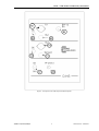
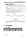
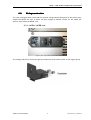
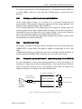
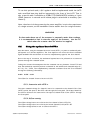
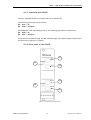
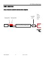
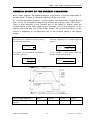
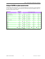
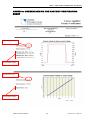
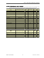
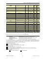
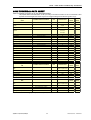
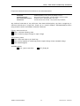
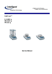
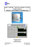
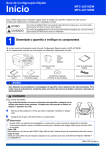
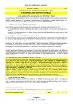
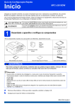
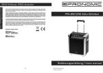
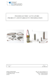
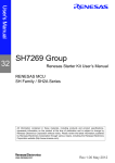
LA75 - LINEAR AMPLIFIER FOR PIEZOELECTRIC ACTUATORS - CA45 COMPACT STANDALONE AMPLIFIER PRODUCT AND WARRANTY INFORMATION Version : 3.2.3 Date: 04/11/13 CEDRAT TECHNOLOGIES SA 59, Chemin du Vieux Chêne - Inovallée F-38246 MEYLAN CEDEX FRANCE URL: http://www.cedrat-technologies.com Email: [email protected] Phone: +33.(0)4.56.58.04.00 Fax: +33.(0)4.56.58.04.01 LA75 – CA45 Product and Warranty information CAUTION: READ BEFORE OPENING For safety purposes these instructions must be read before use of this product. This power amplifier is dedicated to multilayers piezoelectric actuators. Only qualified personnel should work on or around this equipment and only after becoming thoroughly familiar with all warnings, safety notices, and procedures contained herein. The successful and safe operation of this equipment is dependent on proper handling, installation and operation. A "qualified person" is one who is familiar with the installation, construction and operation of the equipment and the hazards involved. In addition, he/she has the following qualifications : is trained and authorized to energize, de-energize, clean, and ground equipment in accordance with established practices, is trained in the proper care and use of protective equipment in accordance with established safety practices. CEDRAT TECHNOLOGIES 2 Version 3.2.3 - 04/11/13 LA75 – CA45 Product and Warranty information TABLE OF CONTENTS 1. SYNOPTIC ................................................................... 5 2. GENERAL DESCRIPTION ................................................... 8 3. MAIN CONNEXIONS ....................................................... 8 3.1. Fuses ....................................................................................................................8 3.2. Voltage selection ...............................................................................................9 3.2.1. 3.2.2. LA75A/ LA75B rack ......................................................................... 9 LA75C rack .................................................................................. 10 4. OPERATING INSTRUCTION FOR THE LINEAR POWER SUPPLY, AC/DC CONVERTER, (LC75X) .................................. 11 5. OPERATING INSTRUCTION FOR THE AMPLIFIER (LA75X) .......... 11 5.1. General instructions ....................................................................................... 11 5.2. Voltage control and current limitation.......................................................12 5.3. Open/closed loop.............................................................................................12 5.4. Using the push–pull mode (optional) (only for LA75X-X).....................12 5.5. Using the optional board CI75-x.................................................................13 5.6. Using the optional board CPH75..................................................................14 5.5.1. 5.5.2. 5.5.3. 5.6.1. 5.6.2. 6. 7. 8. Connection with CI75-x ..................................................................... 13 Offset setting ............................................................................... 13 Front panel of the CI75-x ................................................................. 14 Connection with CPH75 ...................................................................... 15 Front panel of the CPH75 .................................................................. 15 OPERATING INSTRUCTIONS FOR THE SG75 STRAIN GAUGES CONDITIONER .................................................. 16 6.1. General instructions .......................................................................................16 6.2. Thermal effect................................................................................................16 OPERATING INSTRUCTIONS FOR THE ECS75 EDDY CURRENT SENSOR CONDITIONER ...................................... 16 7.1. General instructions .......................................................................................16 7.2. Eddy current displacement sensors ...........................................................17 OPERATING INSTRUCTIONS FOR THE UC45 DIGITAL CONTROLLER (OPTION) .................................................. 18 8.1. Introduction .....................................................................................................18 8.2. Terms and definition......................................................................................18 8.3. Pin out description ..........................................................................................19 CEDRAT TECHNOLOGIES 3 Version 3.2.3 - 04/11/13 LA75 – CA45 Product and Warranty information 9. 8.4. Schematic pin out........................................................................................... 20 8.5. Board Layout ................................................................................................... 20 8.6. Synoptic............................................................................................................ 20 TROUBLE SHOOTING ..................................................... 21 10. WARRANTY CONDITIONS AND EXCEPTIONS......................... 23 11. INSPECTION UPON RECEIPT ............................................ 23 12. AFTER-SALES SERVICE................................................... 23 ANNEX 1 : CONNECTIONS .................................................... 24 Scheme of the cable connection for standard electrical configuration ...... 24 Scheme of the cable connection for the Push Pull electrical configuration 25 ANNEX 2 : EFFECT OF THE CURRENT LIMITATION ...................... 26 Ratings of LA75X-x on piezo actuator series .................................................... 27 ANNEX 3 : UNDERSTANDING THE FACTORY VERIFICATION SHEET....................................................................... 28 ANNEX 4 : LA75A-X TECHNICAL DATA SHEET ........................... 30 LA75B-x TECHNICAL DATA SHEET................................................................... 32 LA75C TECHNICAL DATA SHEET ............................................. 34 CA45 TECHNICAL DATA SHEET ......................................................................... 36 ANNEX 4 : TROUBLE SHOOTING FORM ..................................... 39 CEDRAT TECHNOLOGIES 4 Version 3.2.3 - 04/11/13 LA75 – CA45 Product and Warranty information 1. SYNOPTIC The linear electronic following dimensions: Rack 42F Width : 260 mm Length: 310 mm Height: 160 mm LA75 multi-channel consists in a 19 inches casing to the Rack 63F-4U Width : 365 mm Length: 310 mm Height: 200 mm Rack 84F-4U Width : 470 mm Length: 310 mm Height: 200 mm This electronic is a modular one; which means that a rack42F, for instance, may receive one power supply unit (LC75A) and up to 6 amplification channels, as well as sensors conditioning units: strain gauges sensors conditioner (SG75 unit), eddy current sensors conditioner (ECS75 unit). The rear panel includes the main power connection, the ON/OFF switch and the fuses. The front panel includes the connections with actuators, orders and the switches to close the loop (SERVO) (Cf. Figure 1). The rack can include other boards described in separate documentations. Figure 1 - Front panel of the LA75 power supply CEDRAT TECHNOLOGIES 5 Version 3.2.3 - 04/11/13 LA75 – CA45 Product and Warranty information Nota: “ X ” refers to the “A” ,“B” or “C” version of the driving electronics REFERENCE 1st module DESIGNATION Main power supply unit - LC75X A6 Led protect A7 Vp voltage switch 2nd module Linear amplifier - LA75X B1 Led power supply presence B2 Order BNC connector – channel 1 B3 DC offset order potentiometer (10 turn screw)- channel 1 B4 Closed loop selector (SERVO ON / OFF) – channel 1 B5 LEMO connector for piezo actuator (3 pins lemo for push-pull option)– channel 1 3rd module SG75 – Strain Gauge conditioner (optional) C1 LEMO connector for the gauges bridge – channel 1 C2 BNC connector of the conditioner signal response - channel 1 C3 Regulation potentiometer of the offset (10 turn screw) – channel 1 WARNING A special care in the use of the LEMO connections should be taken in plugging and unplugging them: you have to pull onto the connector and not the cable. It is strictly forbidden to connect the electrical output channels in parallel. CEDRAT TECHNOLOGIES 6 Version 3.2.3 - 04/11/13 LA75 – CA45 Product and Warranty information Figure 2 - Front panel of the CA45 compact standalone amplifier CEDRAT TECHNOLOGIES 7 Version 3.2.3 - 04/11/13 LA75 – CA45 Product and Warranty information 2. GENERAL DESCRIPTION The linear electronic LA75 is dedicated to the supply and control of piezoelectric actuators based on multi-layers piezoelectric ceramics such as APA or PPA from CEDRAT TECHNOLOGIES. The LA75X consists in a power supply with a maximal power given in the attached technical data sheet, including: A linear power supply (LC75X)providing a continuous voltage from the main power (1st module), A linear amplifier (LA75X) dedicated to capacitive load allowing excitation of piezoelectric actuators between –20 and 150 V (2nd module), A strain gauge conditioner (SG75) allowing to measure the displacement of piezoelectric actuators equipped with gauges (optional module), A servo controller (SC75) allowing to close the loop and to insure a feedback control on the actuator (optional module) Figure 3 - Synoptic of the electronic control of a piezo actuator The CA45 compact standalone amplifier consists in a board including the linear power supply providing a continuous voltage from the main power, the linear amplifier, the strain gauge conditioner (option) and a servo controller (SC75) (option). 3. MAIN CONNEXIONS 3.1. Fuses Main: 230 V AC / 50 Hz or : 110 VAC / 60 Hz CA45 LA75A / LA75B LA75C fuse : 250V 1A F type* fuse 1: 250V 2A T type fuse 1: 250V 6.3A T type fuse 2: 250V 2A T type fuse 2: 250V 6.3A T type * CMS fuse : the customer is not allowed to change it without authorisation CEDRAT TECHNOLOGIES 8 Version 3.2.3 - 04/11/13 LA75 – CA45 Product and Warranty information 3.2. Voltage selection The rack is equipped with a main selector (several configurations) integrated to the power entry module that allows the user to select the main voltage by himself, except for the CA45, the selector been inside the RK12F rack. 3.2.1.LA75A/ LA75B rack Figure 4: power entry module of the LA75A/ LA75B rack The voltage selected is visible through the fusedrawer little window (“230” on the figure above). CEDRAT TECHNOLOGIES 9 Version 3.2.3 - 04/11/13 LA75 – CA45 Product and Warranty information To change the voltage: - unplug the power cord - extract the fusedrawer with the 2 fuses - extract the voltage selector (small insert with the “115” and “230” markings, see figure above) - rotate it accordingly. - plug it back in the power entry module - push in the fusedrawer with the 2 fuses mounted on it until it locks itself (“clic” sound). - check to see the desired voltage through the window 3.2.2.LA75C rack Figure 5 : LA75C rack power entry module: 230v selected (left), 115v selected (right) The voltage selected is readable at the bottom of power entry module To change the voltage: - unplug the power cord - extract the fusedrawer with the fuse - rotate it 180 degrees - change place of the fuse - push the fusedrawer back in CEDRAT TECHNOLOGIES 10 Version 3.2.3 - 04/11/13 LA75 – CA45 Product and Warranty information 4. OPERATING INSTRUCTION FOR THE LINEAR POWER SUPPLY, AC/DC CONVERTER, (LC75X) This module produces from the mains, the regulated DC voltage to the amplifier functioning needs: +15 / -15 V : signal processing, +150 V : positive direct voltage, -20 V : negative direct voltage. It is possible to neutralise supplied power voltages by using the switch A7. This switch is the easiest way to disable the piezoelectric actuator as soon as required. However, few seconds are necessary to come to a completely discharged actuator. This module is protected against over temperature, over voltage and over current conditions. It is recommended to keep free space all around the electronic rack while driving in order to make the ventilation easier and to obtain the nominal performance of the driving electronics. Note: Do use the tilt feet for the LA75B and LA75C rack versions. 5. OPERATING INSTRUCTION FOR THE AMPLIFIER (LA75X) 5.1. General instructions The linear amplifier allows to apply to the actuator a signal comparable to the order's one, with a gain of 20 (see Figure 6). offset + Input signal order 20 Voltage amplifier Piezo Actuator Figure 6 - Principle of linear voltage amplifier The order may be applied in two different and complementary manners: static offset (potentiometer): B3 screw, dynamic order: B2 connectors. These two signals are added and their sum should fall between –1V and 7.5V. CEDRAT TECHNOLOGIES 11 Version 3.2.3 - 04/11/13 LA75 – CA45 Product and Warranty information To connect the actuator to the voltage amplifier, the standard cable available is a coaxial LEMO connector in one end and 2 banana plugs in second end (see Annex 1). 5.2. Voltage control and current limitation If the order signal is below –1 V or above 7.5 V, a protective diode and the power amplifier saturation will clamp the signal so that the voltage applied to the actuator stays roughly between –20 V and 150 V. There is some limitation to the constant gain of the amplifier. Indeed, when the variation speed of the input signal (order) increases, the current limitation of the amplifier limits the slew rate of the output voltage. This current limitation varies with the power amplifier (LA75X) version (see annex 3). Note: the use of an digital input signal (B2) may generate parasitic noise so that an additional filter may be necessary. 5.3. Open/closed loop By default, the open/closed loop selector should be set on the mode open loop (SERVO OFF): in that mode, the amplifier applies a voltage gain of 20 to the input. A displacement sensor, its conditioner and a servo controller will be necessary to use the closed loop (SERVO ON); otherwise the order will be set to zero. 5.4. Using the push–pull mode (optional) (only for LA75X-X) For some piezoelectric devices such as the piezoelectric tilts or XY stages, it is necessary to supply two actuators simultaneously. A zero positioning is achieved with an electrical centring. Such a configuration could easily be achieved by using one amplifier, according to the figure shown below. DC Output (LEMO B5) 3 pins LEMO connection (B5) Out PZT (LEMO B5) 20 push-pull cable Voltage amplifier Ground (LEMO B5) b a n a n a p l u g s + Piezo actuator 1 + Piezo actuator 2 - Figure 7 - Principle of power supply for an actuator centred electrically CEDRAT TECHNOLOGIES 12 Version 3.2.3 - 04/11/13 LA75 – CA45 Product and Warranty information To use this optional mode, a DC regulator shall be implemented inside the LA75 and a modified lemo plug shall be integrated in the front of the LA75. That is why a special cable is available at CEDRAT TECHNOLOGIES including a 3 pins LEMO connector in one end and 4 banana plugs in second end is necessary (see Annex 2). Note: the electrical charge seen by the power amplifier is twice the capacitance of a single actuator, so the bandwidth is twice smaller than for a single actuator. WARNING In that mode where one of the actuator is constantly under direct voltage, it is recommended to limit in time the supply of the actuator. Use the A7 switch when the actuator does not need to be supplied. 5.5. Using the optional board CI75-x One alternative, using the Command Inverter board CI75-x, to power a mechanical pushpull system is to use two amplifiers. The first amplifier will receive the direct command signal meanwhile the second have to receive a complementary signal of the first channel. Due to this way of excitation, the mechanical system has to be polarised at its centered position through the command offset. Taking into account the assumption that the command can vary between –1V and 7.5V and that the mechanical centered position is obtained at the middle level command range of ( 8.5 / 2) –1V = 3.25V, The complementary command is obtained from the first command through the following relationship : Vch2 = 3.25V – Vch1 The offset for channel 1 have to be set to 3.25V. 5.5.1.Connection with CI75-x The input command voltage for channel 1 has to be connected to the channel 1 B2 of the LA75-x and at the input of the CI75-x D1 through the front panel. The output channel of the CI75-x D2 has to be connected to the input of channel 2 B6 of the LA75-x through the front panel. 5.5.2.Offset setting The offset voltage has to set to 0V on the first channel of the LA75-x B3. The offset voltage has to set to 0V on the second channel of the LA75-x B7. The offset voltage D3 has to set to 6.5V on the CI75-x. CEDRAT TECHNOLOGIES 13 Version 3.2.3 - 04/11/13 LA75 – CA45 Product and Warranty information 5.5.3.Front panel of the CI75-x D1 D3 D2 D4 D6 D5 Figure 8 : - Front panel of the CI75-x board 5.6. Using the optional board CPH75 The CPH75 board is an analog dephasing circuit that produces an additional command with a settable out of phase. The range of frequency is 500 – 5000 Hz (can be modified at the factory under costumer’s request). The achievable phases range is from –160° to 160°. CEDRAT TECHNOLOGIES 14 Version 3.2.3 - 04/11/13 LA75 – CA45 Product and Warranty information 5.6.1.Connection with CPH75 The user command should be provided to the In connection E1. The following operations are performed : E4 : Out1 = In E6 : Out2 = In*Phase Should Inv E3 is set high (Analog 0-10 V), the following operations are performed : E6 : Out2 = In E4 : Out1 = In*Phase It can be noticed that through the Inv command signal, the relative phase between Out1 and Out2 can be positive or negative. 5.6.2.Front panel of the CPH75 E1 E2 E3 E4 E5 E6 Figure 9 : - Front panel of the CPH75 board CEDRAT TECHNOLOGIES 15 Version 3.2.3 - 04/11/13 LA75 – CA45 Product and Warranty information 6. OPERATING INSTRUCTIONS FOR THE SG75 STRAIN GAUGES CONDITIONER 6.1. General instructions This module allows reading up to three strain gauges bridges. For each one of them, you can: Read the signal emitted by the conditioner (C2), Adjust the offset (C3). The gain and the offset of the conditioner are adjusted at the factory on a gauge bridge set on the piezoelectric actuator, but only the offset is accessible to the user (C3). If you wish to use the conditioner with another actuator, it may be necessary to modify the gain at the factory. 6.2. Thermal effect The strain gauges solution is the easiest way to operate a piezoelectric actuator in a closed loop. The best accuracy that can be achieved with this sensor is around 0.025%. However, the strain gauges sensor is temperature dependent, so that the offset may vary with temperature. 7. OPERATING INSTRUCTIONS FOR THE ECS75 EDDY CURRENT SENSOR CONDITIONER 7.1. General instructions The ECS75 card includes up to 2 channels of Eddy Current sensors, which have been calibrated at the factory. Only the offset can externally corrected (F2, F5 trimmers). CEDRAT TECHNOLOGIES 16 Version 3.2.3 - 04/11/13 LA75 – CA45 Product and Warranty information Figure 10 : - Front panel of the ECS75-2 board 7.2. Eddy current displacement sensors The Eddy Current displacement sensor is a non contact proximity sensor using the eddy current effect generated by the probe in a (preferably) nonferrous material target. The eddy current changes the impedance of the probe, which is read by the conditioner. Although the probe is calibrated with the target, the gain is somewhat dependent on the angle between the probe and the target, the target’s thickness. CEDRAT TECHNOLOGIES 17 Version 3.2.3 - 04/11/13 LA75 – CA45 Product and Warranty information 8. OPERATING INSTRUCTIONS FOR THE UC45 DIGITAL CONTROLLER (OPTION) 8.1. Introduction This mezzanine (optional) board UC45 is stackable on the amplifier board and allows the support of three channels. Only one controller is available on the UC45 board, except in the case of the control of XY stage with Eddy Current Sensors. Only the input and output channel selection is configurable on a single board. Three boards with appropriate input/output selection are necessary for a 3 channel application. The optional board UC45 is available for the boards CA45, LA75A-x, LA75B-x and LA75C-1. It performs digital closed loop control with a PID and output filter configuration. The output filter can be either of type notch or lowpass. The optional board UC45 is delivered with a free standard version (latest version downloadable on the web site) of a (Graphical User Interface) GUI software HPDM45. This GUI is a Labview® executable software (the Labview® from National Instruments is not transferred) and provides the following functionalities: - Remote control of the drive electronic, - Change of the parameters of the controller PID and filter, - Order selection between internal (e.g. generated by the GUI), external (analogue order), - Reading of the calibration parameters of the sensor using the TEDS functionality. For further details, see the user’s manual for the UC45 controller. 8.2. Terms and definition Resolution: the resolution is the smallest displacement that the sensor (and its conditioning electronic) is able to measure. The resolution is preferably given with a relative value (a percentage of the total range of measurement). Precision error in closed loop: the precision error is the difference between the command and the effective value of the displacement. Several contributors play a role in the precision error (resolution of the sensor, sensitivity to external parameters – ageing, temperature …), corrector error. The precision error is preferably given with a relative value (a percentage of the total displacement). The following table gives the performances of the position sensor Sensor type Resolution Strain Gauge (SG) 10-4 Eddy Current Sensor 10-5 (ECS) Capacitive sensor (CS) 10-5 Precision error 10-3 10-4 5.10-5 Most contributing factors Temperature Temperature ; material of the target Tilt effect between the target and the probe Humidity Table 1 : Performances of the sensors CEDRAT TECHNOLOGIES 18 Version 3.2.3 - 04/11/13 LA75 – CA45 Product and Warranty information 8.3. Pin out description JP1 1 2 3 4 5 6 7 8 9 10 11 12 13 14 GND SDI / MISO SDO /MOSI SC / SCLK GND +15 -15 +5 GND CS_Ad0 CS_Ad1 CS_Ad2 GND GND Ground SPI Master Serial Data In (MISO) SPI Master Serial Datat out (MOSI) SPI Serial Clock Ground +15V supply -15V supply +5V supply Ground Chip Select adress 0 / LSB Chip Select adress 1 Chip Select adress 2 / MSB Ground Ground Table 2: Connector Jp1 Pin Out JP2 1 2 3 4 5 6 7 8 9 10 11 12 13 14 PID3 MeasSensor3 SGOut3 Order3 GND PID1 MeasSensor2 SGOut2 Order2 GND PID1 MeasSensor1 SGOut1 Order1 Controler output Same as SG Out but inverted or not depending board setting Strain gages conditionner output Command signal Channel 3 Channel 3 Channel 3 Channel 3 Controler output Same as SG Out but inverted or not depending board setting Strain gages conditionner output Command signal Channel 2 Channel 2 Channel 2 Channel 2 Controler output Same as SG Out but inverted or not depending board setting Strain gages conditionner output Command signal Channel1 Channel1 Channel1 Channel1 Table 3 Connector Jp1 Pin Out CEDRAT TECHNOLOGIES 19 Version 3.2.3 - 04/11/13 LA75 – CA45 Product and Warranty information 8.4. Schematic pin out JP1 GND JP2 1 2 3 4 5 6 7 8 9 10 11 12 13 14 SDi SDo SC GND +15 -15 5 GND CS_Ad0 CS_Ad1 CS_Ad2 GND 1 2 3 4 5 6 7 8 9 10 11 12 13 14 Header 14 PID3 MeasSensor3 SGout3 Order3 GND PID2 MeasSensor2 SGout2 Order2 GND PID1 MeasSensor1 SGout1 Order1 Header 14 Figure 11: Schematic pin out of the connector 8.5. 8.6. Board Layout Synoptic Figure 12: Top view of the board Figure 13: Synoptic of the UC45 controller CEDRAT TECHNOLOGIES 20 Version 3.2.3 - 04/11/13 LA75 – CA45 Product and Warranty information 9. TROUBLE SHOOTING PROBLEMS: THE PLUGGED PIEZO ACTUATOR DOES NOT MOVE WHILE THE REAR CONNECTION AND THE A7 ARE SWITCHED ON ACTION POSSIBLE CAUSES Check the led A6 : a) If A6 is off - check the main cable and the fuses at the rear panel b) If A6 is red - - check the connection lines to the piezo actuator / disconnect every LEMO cable. Test the electronics with the unplugged and plugged piezo actuator, as follows - switch A7 off If A6 is green - switch A7 on if the electronics works, - if the electronics doesn’t work, - If A6 is red - Wait for 10 minutes and switch A7 on if the electronics works, if the electronics doesn’t work, PROBLEMS: - misconnection with main cable or burnt fuses The electronics is in protection May be a short circuit through the cable connection or through the piezo actuator occurred an external parasitic noise might have disturbed it a breakdown is certain The electronics was in thermal protection and needed to cool itself down a breakdown is certain INCOHERENT RESPONSE FROM THE ACTUATOR IN OPEN LOOP ACTION Check the output signal (B5) - POSSIBLE CAUSES the DC offset may be wrong If the DC offset is wrong, turn (B3) to settle it* PROBLEMS: INCOHERENT RESPONSE FROM THE ACTUATOR IN CLOSED LOOP ACTION POSSIBLE CAUSES Go back in mode SERVO OFF (B4) and check the the strain gauges offset (C3) may be wrong sensor's response (C2)** * 10 turns potentiometers are used: do not hesitate to rotate the potentiometers and keep attention to the ‘clic’ noise arising at the end of the trimmer range. CEDRAT TECHNOLOGIES 21 Version 3.2.3 - 04/11/13 LA75 – CA45 Product and Warranty information ** Adjusting the Strain Gauge offset - Apply a command of 0V (by a 50 Ohms BNC connector on B2 for instance), - Check that the voltage output on B5 is nearly zero, - Adjust the potentiometer B3 to get the output B5 near zero, - Measure the output of the Strain Gauge conditioner C2, - Adjust the potentiometer C3, so that the output C2 is 0.38 V One has : Vsg =(SetPointLA + 1) / MaxAmplitudeLA * MaxAmplitudeSG - 0,5 With : MaxAmplitudeLA = 8.5 MaxAmplitudeSG = 7.5 CEDRAT TECHNOLOGIES 22 Version 3.2.3 - 04/11/13 LA75 – CA45 Product and Warranty information The customer is not entitled to modify the power supply or the linear amplifier. The only manipulations allowed to him are described in the set here above, including the replacement of (the) external fuse(s.). For any other matter or breakdown suspicion, we suggest the customer to contact the local vendor. 10. WARRANTY CONDITIONS AND EXCEPTIONS The equipment is warranted for one year, including parts and labour, and only under standard technical conditions as outlined above and expressly mentioned in the technical data sheet. Repairs will be carried out at CEDRAT TECHNOLOGIES or through your vendor. Shipping, handling and insurance costs to return a part for repair must be paid by the customer. Interventions or attempts to service or repair the LA75 by any unauthorised persons will invalidate this warranty. 11. INSPECTION UPON RECEIPT This product has been inspected and shown to operate correctly at the time of shipment, as verified by the Factory Verification Form that accompanies the power supply Immediately upon receipt of the product, it should be inspected carefully for any signs of damage that may have occurred during shipment. If any damage is found, a claim should be filed with the carrier. The package should also be inspected for completeness according to the enclosed packing list. If an order is incorrect or incomplete, contact your distributor. CEDRAT TECHNOLOGIES recommends the customer to keep the original package for any further carriage of the electronic product. 12. AFTER-SALES SERVICE If a device requires service, please contact CEDRAT TECHNOLOGIES or your local vendor. Please include the device model and serial number in all correspondence with CEDRAT TECHNOLOGIES or your vendor. CEDRAT TECHNOLOGIES 23 Version 3.2.3 - 04/11/13 LA75 – CA45 Product and Warranty information ANNEX 1 : CONNECTIONS Scheme of the cable connection for standard electrical configuration Banana plugs (male) Coaxial LEMO connector Banana plugs (female) Piezo Actuator Electrical cable (1.50 m) for standard connection Lemo Driving electronics connection channel x Amplifier Output 0V CEDRAT TECHNOLOGIES 24 Version 3.2.3 - 04/11/13 LA75 – CA45 Product and Warranty information Scheme of the cable connection for the Push Pull electrical configuration Banana plugs (male) Banana plugs (female) 3 pins LEMO connector Driving electronics connection channel x DC Output Piezo Actuator No 1 Electrical cable (1.50 m) for push pull connection Piezo Actuator No 2 Lemo Amplifier Output 0V CEDRAT TECHNOLOGIES 25 Version 3.2.3 - 04/11/13 LA75 – CA45 Product and Warranty information ANNEX 2 : EFFECT OF THE CURRENT LIMITATION With a linear amplifier the applied voltage to the actuator is directly proportional to the input signal. The gain of the power amplifier LA75x is set to 20. So, to obtain the whole stroke of a given actuator, one should input a signal varying from –1V to 7.5V. The applied voltage on the actuator will then vary from –20 to 150V. There is some limitation to the constant gain of the amplifier. Indeed, when the variation speed of the input signal (order) increases, the current limitation of the amplifier limits the slew rate of the output voltage. The current provided to a piezo ceramic is depending on its capacitance and on the variation speed of the applied voltage. The current for a capacitive load is given by the following expression: I piezo C piezo The max frequency for a triangle signal is given by: dv dt f triangle max For a given current limitation, the shortest load time is given by: tload I lim 2 V C piezo If we consider a sine signal, then the maximal frequency is given by: V C piezo f sin max I lim 2 I lim V C piezo 2 Figure A 1 - The current limitation limits the voltage slew rate of the piezo Type of linear amplifier CA45 Current limitation (A) per 0.03 channel CEDRAT TECHNOLOGIES LA75A 0.09 26 LA75B 0.36 LA75C 2.4 Version 3.2.3 - 04/11/13 LA75 – CA45 Product and Warranty information Ratings of LA75X-x on piezo actuator series Considering a scale variation of V = 120V and taking into account the current limitation of the LA75X, the following table summarises the load time and bandwidth values for different piezo actuator series : Actuator serie Capacitance Load time @ 120 V (ms) µF MLA_2*5*10 - APA - XS 0,25 1,00 0,33 0,08 0,01 MLA_5*5*20 - APA - S, SM 1,55 6,20 2,07 0,52 0,08 APA - M 3,15 12,60 4,20 1,05 0,16 APA - ML 20,00 80,00 26,67 6,67 1,00 APA - L 40,00 160,00 53,33 13,33 2,00 APA - XL 110,00 440,00 146,67 36,67 5,50 MLA_5*5*10 - PPA10M 0,70 2,80 0,93 0,23 0,04 PPA20M 1,40 5,60 1,87 0,47 0,07 PPA40M 2,70 10,80 3,60 0,90 0,14 PPA40L 13,30 53,20 17,73 4,43 0,67 PPA60L 20,00 80,00 26,67 6,67 1,00 PPA80L 26,60 106,40 35,47 8,87 1,33 PPA40XL 24,00 96,00 32,00 8,00 1,20 PPA80XL 48,00 192,00 64,00 16,00 2,40 PPA120XL 72,00 288,00 96,00 24,00 3,60 (*) the capacitance values are those at low frequency and room temperature. CEDRAT TECHNOLOGIES 27 Version 3.2.3 - 04/11/13 LA75 – CA45 Product and Warranty information ANNEX 3 : UNDERSTANDING THE FACTORY VERIFICATION SHEET Representative load Verification tests Representative load Verification tests CEDRAT TECHNOLOGIES 28 Version 3.2.3 - 04/11/13 LA75 – CA45 Product and Warranty information Serial number of the associated actuator SG conditioner gain calibration CEDRAT TECHNOLOGIES 29 Version 3.2.3 - 04/11/13 LA75 – CA45 Product and Warranty information ANNEX 4 : LA75A-X TECHNICAL DATA SHEET 1 Table of standard properties of use and measurement The properties defined in the table below, are set up according to the technical conditions of use and measurement. These properties are warranted within their variation range and in compliance with the standard technical conditions of use. Properties LA75A-x Standard technical conditions Unit Notes Nominal values Min. values Max. values x : number of channel Function Linear amplifier Max. number of channels 3 Natural convection (Forced convection for 3 channels) Cooling Protection Thermal Negative supply voltage Standard environment V -36 -30,0 -40,0 Positive supply voltage Standard environment V 165 160,0 180,0 Min. input voltage Standard environment V -1,2 -1,3 -1,1 Max. input voltage Standard environment V 7,7 7,6 7,9 Min. output voltage Standard environment V -20 -20,0 -24,0 Max. output voltage Standard environment V 150 150,0 156,0 Gain Standard environment V/V 20 19,8 20,2 Max. output current A 0,09 0,09 0,12 Max. output load capacitance µF 400 360,0 440,0 Signal to noise ratio Noise measurement conditions Unloaded output bandwith (-3dB) Loaded Output bandwidth (-3dB) Standard load Input impedance Mass Dimensions Option SC75 Standard technical conditions dB 85 70,0 100,0 Hz 33000 29700 36300 Hz 154 138,6 169,4 kOhms 10 9,5 10,5 g 800 - - mm 10F wide, 3H high Unit Nominal values Min. values Max. values Notes Option on amplifier board Function Signal to noise ratio Servo controller Noise measurement conditions Output bandwidth* Accuracy (closed loop) Standard environment dB 80 68 92 Hz 2000 1800 2200 % 0,1 0,07 0,13 *Bandwidth settled according to your specifications; by default 1 Hz. 1 In all CEDRAT TECHNOLOGIES SA documents, the decimal sign is a comma on the line (ISO 31-0:1992). CEDRAT TECHNOLOGIES 30 Version 3.2.3 - 04/11/13 LA75 – CA45 Product and Warranty information Properties LC75A Standard technical conditions Unit Nominal values Notes Min. values Max. values 250 - Function Bipolar AC/DC linear converter Cooling Natural convection Thermal Overcurrent Overvoltage Protection Main voltage Standard main supply VAC 230 190 Main frequency Standard main supply Hz 50 45 65 Negative output voltage Standard environment VDC -36 -30,0 -40,0 Positive output voltage Standard environment VDC 165 160,0 180,0 Current limitation Standard environment A 0,12 0,114 0,126 g 680 - - mm 12F wide, 3H high - - Unit Nominal values Min. values Max. values -15,8 Mass Dimensions Properties SG75-x Standard technical conditions Notes x : number of channel Fonction Strain Gauges conditioner Max. number of channels 3 Min. supply voltage VDC -15 -14,3 Max. supply voltage VDC 15 14,3 15,8 Min. output voltage VDC -12 -11,4 -12,6 Max. output voltage VDC 12 11,4 12,6 dB 70 56,0 84,0 Hz 2000 1600 2400 g 150 - - mm 6F wide, 3H high Signal to noise ratio Noise measurement conditions Output bandwith (-3dB)* Mass Dimensions *Bandwidth settled according to your specifications Properties standard technical conditions of use and measurement Quasistatic excitation Environment Standard main supply Noise measurement conditions Standard load : : : : : AC voltage between –20 and 150 V at 1 Hz Ambient temperature (15-25°C) and dry air (Humidity < 50 % rH) Main according to directive HD472; could be adapted to 110 VAC on request Excitation 0.5 Vrms ; reading bandwidth 1 Hz to 1 kHz Actuator APA from series S or SM : 1.55 µF (load test may be different) Any technical conditions of use, different from those defined above, can lead to temporary or definitive alterations of properties. Thank you to contact CEDRAT TECHNOLOGIES before using actuators under non standard technical conditions. Factory tests carried out Test 1: Load and discharge time Test 2: Linearity output voltage vs. input voltage Extra factory tests Test 3: Gain and linearity in closed loop Test 4: Step response in closed loop (sensor output voltage versus command voltage Test 5: Thermal test at full load Available options [ SC ] Servo controller [ PP ] Push-pull CEDRAT TECHNOLOGIES 31 Version 3.2.3 - 04/11/13 LA75 – CA45 Product and Warranty information LA75B-x TECHNICAL DATA SHEET Table of standard properties of use and measurement The properties defined in the table below, are set up according to the technical conditions of use and measurement. These properties are warranted within their variation range and in compliance with the standard technical conditions of use. Properties LA75B-x Standard technical conditions Unit Notes Nominal values Min. values Max. values x : number of channel Function Linear amplifier Max. number of channels 2 Natural convection (Forced convection for 2 channels) Cooling Protection Thermal Negative supply voltage Standard environment V -36 -30,0 -40,0 Positive supply voltage Standard environment V 165 160,0 180,0 -1,1 -1,3 Min. input voltage Standard environment V -1,2 Max. input voltage Standard environment V 7,7 7,6 7,9 Min. output voltage Standard environment V -20 -20,0 -24,0 156,0 Max. output voltage Standard environment V 150 150,0 Gain Standard environment V/V 20 19,8 20,2 A 0,36 0,360 0,400 µF 400 360,0 440,0 dB 85 70,0 100,0 Hz 33000 29700 36300 Max. output current Max. output load capacitance Signal to noise ratio Noise measurement conditions Unloaded output bandwith (-3dB) Loaded Output bandwidth (-3dB) Hz 616 554,5 677,7 kOhms 10 9,5 10,5 Mass kg 1 - - Dimensions mm 10F wide, 3H high Unit Nominal values Min. values Max. values Standard load Input impedance Option SC75 Standard technical conditions Notes Option on amplifier board Function Signal to noise ratio Servo controller Noise measurement conditions Output bandwidth* Accuracy (closed loop) Standard environment dB 80 68 92 Hz 2000 1800 2200 % 0,1 0,07 0,13 *Bandwidth settled according to your specifications; by default 1 Hz. CEDRAT TECHNOLOGIES 32 Version 3.2.3 - 04/11/13 LA75 – CA45 Product and Warranty information Properties LC75B Standard technical conditions Unit Nominal values Notes Min. values Max. values 250 - Function Bipolar AC/DC linear converter Cooling Forced air Protection Thermal Overcurrent Overvoltage Main voltage Standard main supply VAC 230 190 Main frequency Standard main supply Hz 50 45 65 Negative output voltage Standard environment VDC -36 -30,0 -40,0 Positive output voltage Standard environment VDC 165 160,0 180,0 Current limitation Standard environment A 0,60 0,57 0,63 g 680 - - mm 12F wide, 3H high - - Unit Nominal values Min. values Max. values Mass Dimensions Properties SG75-x Standard technical conditions Notes x : number of channel Fonction Strain Gauges conditioner Max. number of channels 3 Min. supply voltage VDC -15 -14,3 -15,8 Max. supply voltage VDC 15 14,3 15,8 Min. output voltage VDC -12 -11,4 -12,6 Max. output voltage VDC 12 11,4 12,6 dB 70 56,0 84,0 Hz 2000 1600 2400 g 150 - - mm 6F wide, 3H high Signal to noise ratio Noise measurement conditions Output bandwith (-3dB)* Mass Dimensions *Bandwidth settled according to your specifications Properties standard technical conditions of use and measurement Quasistatic excitation Environment Standard main supply Noise measurement conditions Standard load : : : : : AC voltage between –20 and 150 V at 1 Hz Ambient temperature (15-25°C) and dry air (Humidity < 50 % rH) Main according to directive HD472; could be adapted to 110 VAC on request Excitation 0.5 Vrms ; reading bandwidth 1 Hz to 1 kHz Actuator APA from series S or SM : 1.55 µF (load test may be different) Any technical conditions of use, different from those defined above, can lead to temporary or definitive alterations of properties. Thank you to contact CEDRAT TECHNOLOGIES before using actuators under non standard technical conditions. Factory tests carried out Test 1: Load and discharge time Test 2: Linearity output voltage vs. input voltage Extra factory tests Test 3: Gain and linearity in closed loop Test 4: Step response in closed loop (sensor output voltage versus command voltage Test 5: Thermal test at full load Available options [ SC ] Servo controller CEDRAT TECHNOLOGIES [ PP ] Push-pull 33 Version 3.2.3 - 04/11/13 LA75 – CA45 Product and Warranty information LA75C TECHNICAL DATA SHEET The properties defined in the table below, are set up according to the technical conditions of use and measurement. These properties are warranted within their variation range and in compliance with the standard technical conditions of use. Properties LA75C Standard technical conditions Unit Notes Min. values Nominal values Max. values - Function Linear amplifier Max. number of channels 1 Cooling Forced air Protection Thermal Short circuit Negative supply voltage Standard environment V -36 -30,0 -40,0 Positive supply voltage Standard environment V 165 160,0 180,0 Min. input voltage Standard environment V -1,2 -1,1 -1,3 Max. input voltage Standard environment V 7,7 7,6 7,9 Min. output voltage Standard environment V -20 -20,0 -24,0 Max. output voltage Standard environment V 150 150,0 156,0 Gain Standard environment V/V 20 19,8 20,2 A 2,40 2,30 2,50 µF 400 360,0 440,0 dB 85 70,0 100,0 Hz 33000 29700 36300 Max. output current Max. output load capacitance Signal to noise ratio Noise measurement conditions Unloaded output bandwith (-3dB) Loaded Output bandwidth (-3dB) Standard load Input impedance Mass Dimensions Option SC75 Standard technical conditions Hz 4107 3697 4518 kOhms 10 9,5 10,5 g 860 - - mm 18F wide, 4H high Unit Nominal values Min. values Max. values Notes Option on amplifier board Function Signal to noise ratio Servo controller Noise measurement conditions Output bandwidth* Accuracy (closed loop) Standard environment dB 80 68 92 Hz 2000 1800 2200 % 0,1 0,07 0,13 *Bandwidth settled according to your specifications; by default 1 Hz. CEDRAT TECHNOLOGIES 34 Version 3.2.3 - 04/11/13 LA75 – CA45 Product and Warranty information Properties LC75C Standard technical conditions Unit Nominal values Notes Min. values Max. values 250 - Function Bipolar AC/DC linear converter Cooling Forced air Protection Thermal Overcurrent Overvoltage Main voltage Standard main supply VAC 230 190 Main frequency Standard main supply Hz 50 45 65 Negative output voltage Standard environment VDC -36 -30,0 -40,0 Positive output voltage Standard environment VDC 165 160,0 180,0 Current limitation Standard environment A 2,40 2,28 2,52 g 680 - - mm 12F wide, 3H high - - Unit Nominal values Min. values Max. values -15,8 Mass Dimensions Properties SG75-x Standard technical conditions Notes x : number of channel Fonction Strain Gauges conditioner Max. number of channels 3 Min. supply voltage VDC -15 -14,3 Max. supply voltage VDC 15 14,3 15,8 Min. output voltage VDC -12 -11,4 -12,6 VDC 12 11,4 12,6 dB 70 56,0 84,0 Hz 2000 1600 2400 g 150 - - mm 6F wide, 3H high Max. output voltage Signal to noise ratio Noise measurement conditions Output bandwith (-3dB)* Mass Dimensions *Bandwidth settled according to your specifications Properties standard technical conditions of use and measurement Quasistatic excitation Environment Standard main supply Noise measurement conditions Standard load : : : : : AC voltage between –20 and 150 V at 1 Hz Ambient temperature (15-25°C) and dry air (Humidity < 50 % rH) Main according to directive HD472; could be adapted to 110 VAC on request Excitation 0.5 Vrms ; reading bandwidth 1 Hz to 1 kHz Actuator APA from series S or SM : 1.55 µF (load test may be different) Any technical conditions of use, different from those defined above, can lead to temporary or definitive alterations of properties. Thank you to contact CEDRAT TECHNOLOGIES before using actuators under non standard technical conditions. Factory tests carried out Test 1: Load and discharge time Test 2: Linearity output voltage vs. input voltage Extra factory tests Test 3: Gain and linearity in closed loop Test 4: Step response in closed loop (sensor output voltage versus command voltage Test 5: Thermal test at full load Available options [ SC ] Servo controller [ PP ] Push-pull CEDRAT TECHNOLOGIES 35 Version 3.2.3 - 04/11/13 LA75 – CA45 Product and Warranty information CA45 TECHNICAL DATA SHEET Table of standard properties of use and measurement The properties defined in the table below, are set up according to the technical conditions of use and measurement. These properties are warranted within their variation range and in compliance with the standard technical conditions of use. Properties CA45 Standard technical conditions Unit Notes Nominal values Min. values Max. values - Function Standalone voltage amplifier Cooling Natural convection Thermal Overcurrent Overvoltage Protection Main voltage Standard main supply VAC 230 190,0 250,0 Main frequency Standard main supply Hz 50 45,0 65,0 Min. input voltage Standard environment V -1,2 -1,5 -1,2 Max. input voltage Standard environment V 7,7 7,7 7,9 Min. output voltage Standard environment V -20 -20,0 -25,0 Max. output voltage Standard environment V 150 150,0 160,0 Gain Standard environment V/V 20 19,8 20,2 A 0,03 0,030 0,045 µF 400 360,0 440,0 dB 85 80,0 90,0 Hz 10000 9000 11000 Max. output current Max. output load capacitance Signal to noise ratio Noise measurement conditions Unloaded output bandwith (-3dB) Loaded Output bandwidth (-3dB) Standard load Input impedance Mass Dimensions Option SG Standard technical conditions Hz 154 154,0 169,4 kOhms 10 9,5 10,5 g 1200 - - mm 12F wide, 3H high Unit Nominal values Min. values Max. values Notes Option on amplifier board Function Servo controller Signal to noise ratio Noise measurement conditions dB 85 80 90 Output bandwidth* Hz 2000 1800 2200 Accuracy (closed loop) % 0,1 0,07 0,13 Unit Nominal values Min. values Max. values Option ECS Standard technical conditions Notes Option on amplifier board Function Signal to noise ratio Servo controller Noise measurement conditions dB 100 85 100 Output bandwidth* Hz 10000 9000 11000 Accuracy (closed loop) % 0,01 0,007 0,013 *Bandwidth settled according to your specifications; by default 1 Hz. CEDRAT TECHNOLOGIES 36 Version 3.2.3 - 04/11/13 LA75 – CA45 Product and Warranty information Properties standard technical conditions of use and measurement Quasistatic excitation Environment Standard main supply Noise measurement conditions Standard load : : : : : AC voltage between –20 and 150 V at 1 Hz Ambient temperature (15-25°C) and dry air (Humidity < 50 % rH) Main according to directive HD472; could be adapted to 110 VAC on request Excitation 0.5 Vrms ; reading bandwidth 1 Hz to 1 kHz Actuator APA from series S or SM : 1.55 µF (load test may be different) Any technical conditions of use, different from those defined above, can lead to temporary or definitive alterations of properties. Thank you to contact CEDRAT TECHNOLOGIES before using actuators under non standard technical conditions. Factory tests carried out Test 1: Load and discharge time Test 2: Linearity output voltage vs. input voltage Extra factory tests Test 3: Gain and linearity in closed loop Test 4: Step response in closed loop (sensor output voltage versus command voltage Test 5: Bode diagram Available options [ SC ] Servo controller CEDRAT TECHNOLOGIES [ PP ] Push-pull 37 Version 3.2.3 - 04/11/13 LA75 – CA45 Product and Warranty information CEDRAT TECHNOLOGIES 38 Version 3.2.3 - 04/11/13 LA75 – CA45 Product and Warranty information ANNEX 4 : TROUBLE SHOOTING FORM In case of trouble or breakdown with the electronic device, this form must be completed by the customer in order to : - allow Cedrat Technologies to authorise the product return back to the factory, - help Cedrat Technologies in repairing it. Product: Please give mention here the references and delivery date, History: Please summarise here every action which has been performed with the device since the delivery, Problem description: Please describe here the problems faced with the electronics and which are not described in the paragraph 7, Notations: Please define here the short term used for external devices plugged in the electronics in order to make the writing of “problem identification” easier, Problem identification: Please summarise and describe here, using the “notations”, the operation that could lead to problem identification, Action: Please mention and update here every action undertaken by yourself, by Cedrat Technologies or by your local vendor, Please note that you need to get the authorisation from CEDRAT TECHNOLOGIES before sending back the hardware. CEDRAT TECHNOLOGIES 39 Version 3.2.3 - 04/11/13