1
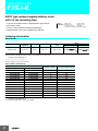
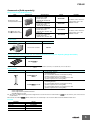
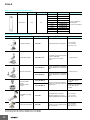
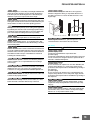
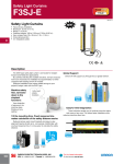
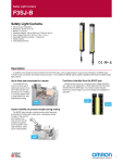
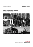
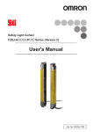
Safety Light Curtains
F3SJ-E
F3SJE
For full product information, visit www.sti.com. Use the SpeedSPEC Code for quick access to the specific web page.
Safety Light Curtains
•
•
•
•
•
•
•
•
Fast and easy installation
Resolution: 25 mm (1.01 in.)
Range: 7 m (23 ft.)
Protected heights: 185 to 1105 mm (7.28 to 43.50 in.)
Very compact size: 30 x 30 mm (1.18 x 1.18 in.)
Cross-talk prevention
3 m integrated cables
A Rapid Delivery Product: Select models are available for
shipment today or within 3 to 5 days
Description
The EASY type safety light curtain is well suited for straightforward on/off detection applications.
By carefully selecting the available functions, we have reduced
man hours necessary for installation by approximately 1/2 when
compared with existing STI models.
Reduced installation time means added savings to your
project’s budget, start with the EASY type.
Machine safety
first, narrowed
down to the
simplest
functions:
Global Support
Omron will support you through the our global network.
I only need
simple
functions
Global
Support
Upon detection
of personnel, the
machine stops.
Simple yet very
optimal.
Easy-to-view Diagnostics
1/2 the mounting time. Fixed response time
makes calculation of the safety distance easier.
These indicators enable you to intuitively know the status
and cause of any error. This allows faster installation while
reducing machine down time.
Reduced wiring, quick mount brackets and easy-to-view
alignment beams all add up to cost savings. Additionally, with
one fixed response time, it is now easier to calculate the safety
distance.
Easy-to-View
Diagnostics
mounting time
Mounting Time
Existing
models
E type
Select models are available for Rapid Delivery.
Visit this product on www.sti.com for details.
www.sti.com/info
Safety Light Curtain
F3SJ-E
EASY type reduces implementation costs
with 1/2 the mounting time.
• In pursuit of simple functions: Upon detection of personnel,
the machine stops.
• Can be used for simple hand intrusion detection.
• Implementation costs can be significantly reduced.
Dimensions
Related
information Function List
: Page 54 to 60
: Page 97 to 97
Safety Precautions
: Page 99
Precautions on Safety : Page 100 to 104
Ordering Information
Main Units
Safety Light Curtain
Application
Detection
capability
Beam gap
Operating range
Protective height
(mm)
Hand protection
Dia. 25 mm
20 mm
0.2 to 7 m
185 to 1,105
Model
PNP output
F3SJ-E@@@@P25
F3SJ-E@@@@N25
*1
Note: F3SJ-E uses a 3 m prewired discrete cable.
*1. For S-mark compatible model, the suffix "-S" is added to the model name.
(Example) F3SJ-E0185P25-S
Safety Light Curtain Model List
Please contact our sales representative.
F3SJ-E Series (20 mm pitch)
Model
Number of beams
2
Protective height [mm] *2
PNP output *1
NPN output
F3SJ-E0185P25
F3SJ-E0185N25
8
185
F3SJ-E0225P25
F3SJ-E0225N25
10
225
F3SJ-E0305P25
F3SJ-E0305N25
14
305
F3SJ-E0385P25
F3SJ-E0385N25
18
385
F3SJ-E0465P25
F3SJ-E0465N25
22
465
F3SJ-E0545P25
F3SJ-E0545N25
26
545
F3SJ-E0625P25
F3SJ-E0625N25
30
625
F3SJ-E0705P25
F3SJ-E0705N25
34
705
F3SJ-E0785P25
F3SJ-E0785N25
38
785
F3SJ-E0865P25
F3SJ-E0865N25
42
865
F3SJ-E0945P25
F3SJ-E0945N25
46
945
F3SJ-E1025P25
F3SJ-E1025N25
50
1,025
F3SJ-E1105P25
F3SJ-E1105N25
54
1,105
*1. For S-mark compatible model, the suffix "-S" is added to the model name.
(Example) F3SJ-E0185P25-S
*2. Protective height (mm) = Total sensor length
NPN output
F3SJ-E
Accessories (Sold separately)
Relays with Forcibly Guided Contacts
Type
Appearance
G7SA Relays with
Forcibly Guided Contacts
G7S-@-E Relays with
Forcibly Guided Contacts
Specifications
• Nodes: 4
• Contact type: 2A2B
• Rated switch load:
250 VAC 6A, 30 VDC 6A
• Nodes: 4
• Contact type: 3NO+1NC
• Rated switch load:
250 VAC 6A, 30 VDC 6A
• Nodes: 6
• Contact type: 4NO+2NC
• Rated switch load:
250 VAC 10 A, 30 VDC 10 A
• Nodes: 6
• Contact type: 3NO+3NC
• Rated switch load:
250 VAC 10 A, 30 VDC 10 A
Model
Remarks
G7SA-2A2B
For details on other models or
socket models, refer to the
OMRON's website.
G7SA-3A1B
G7S-4A2B-E
For details on other models or
socket models, refer to the
OMRON's website.
G7S-3A3B-E
Laser Pointer
Appearance
Output
Model
Laser Pointer for F3SJ
F39-PTJ
Spatter Protection Cover (2 cables per set, common for emitter/receiver) (10% Operating Range Attenuation)
Appearance
Model
F39-HB@@@@ *
* The same 4-digit numbers as the protective heights (@@@@ in the light curtain model names) are substituted by in the model names.
Protective Bar
Appearance
Model
F39-PB@@@@ *1
F39-PB@@@@-S *1 *2
Remarks
• 2 Light Curtain brackets
• 4 mounting brackets
• 0 to 4 intermediate brackets for backside mounting
(quantity required for the sensing width)
• 0 to 4 intermediate brackets for mounting to the sides
(quantity required for the sensing width)
• 1 Light Curtain bracket
• 2 mounting brackets
• 0 to 2 intermediate brackets for backside mounting
(quantity required for the sensing width)
• 0 to 2 intermediate brackets for mounting to the sides
(quantity required for the sensing width)
Note: The following are not provided with the Protective Bars.
• Safety Light Curtain
• Safety Light Curtain Top/Bottom Brackets
• Wall Mounting Screw Unit
*1. The same four digits indicating protective height that are used in the Sensor model number (@@@@) are used in the part of the Protector
model number.
*2. Purchase the F39-PB@@@@ (which contains two sets of brackets) to use Protective Bars for both the Emitter and Receiver.
Test rod
Diameter
14mm dia.
20mm dia.
25mm dia.
30mm dia.
Model
F39-TRD14
F39-TRD20
F39-TRD25
F39-TRD30
3
F3SJ-E
Mirrors (12% Operating Range Attenuation)
Appearance
Mirror material
Width (mm)
Glass mirror
Thickness (mm)
145
32
Length (mm)
Model
406
F39-MLG0406
610
F39-MLG0610
711
F39-MLG0711
914
F39-MLG0914
1,067
F39-MLG1067
1,219
F39-MLG1219
1,422
F39-MLG1422
1,626
F39-MLG1626
1,830
F39-MLG1830
2,134
F39-MLG2134
Remarks
2 sets of Cylindrical
mounting rod,
4 screws are included.
Sensor Mounting Bracket (Sold separately)
Appearance
Specifications
Model
Application
Top/bottom bracket
F39-LJB1
Top/bottom bracket for F3SJ-E/B
2 for an emitter,
2 for a receiver,
total of 4 per set
Intermediate bracket
F39-LJB2 *1 *2
In combination use with top/bottom
bracket for F3SJ-E/B
Can be used as free-location
bracket.
1 set with 2 pieces
F39-LJB3-M6 *1
Quick mount bracket for F3SJ-E/B
Supports M6 slide nut for aluminum
frame.
F39-LJB3-M8 *2
Quick mount bracket for F3SJ-E/B
Supports M8 slide nut for aluminum
frame.
Quick mount bracket
Quick mount M6
bracket
Quick mount M8
bracket
1 set with 2 pieces
Hexagon socket head cap
screws (M6 x 10) are
included.
F39-LJB3-M6K *1
F39-LJB3-M8K *2
Bracket to mount an intermediate
bracket to the aluminum frame with
Hexagon socket head cap
a single touch.
screws (M8 x 14) are
included.
Compatible mounting
bracket
F39-LJB4
Mounting bracket used when
2 for an emitter,
replacing existing area sensors
2 for a receiver,
(F3SJ-A or F3SN) with the F3SJ-E/B. total of 4 per set
Contact mount bracket
F39-LJB5
Bracket to closely contact the back
side of the Sensor.
Note: All the sensor mounting brackets for F3SJ-E are sold separately.
*1. Combining F39-LJB2 and F39-LJB3-M6K makes F39-LJB3-M6.
*2. Combining F39-LJB2 and F39-LJB3-M8K makes F39-LJB3-M8.
4
Remarks
2 for an emitter,
2 for a receiver,
total of 4 per set
F3SJ-E
Specifications (For details, refer to the instruction manual or User's manual.)
Main Units
F3SJ-E@@@@P25/N25
Model
PNP output
NPN output
Sensor type
Setting tool connection *1
Safety category
Detection capability
Beam gap (P)
Number of beams (n)
Protective height (PH)
Lens diameter
Operating range *2
Response time
ON to OFF
(under stable light
incident condition) OFF to ON
Startup waiting time
Power supply voltage (Vs)
Consumption
current
(no load)
PNP output
NPN output
Light source (emitted wavelength)
Effective aperture angle (EAA)
Safety outputs
(OSSD)
PNP output
NPN output
F3SJ-E@@@@P25
F3SJ-E@@@@N25
Type 4 safety light curtain
Parameter settings: Not available
Safety purpose of category 4, 3, 2, 1, or B
Opaque objects 25 mm in diameter
20 mm
8 to 54
185 to 1,105 mm
Diameter 5 mm
0.2 to 7 m
15 ms max.
70 ms max.
2 s max.
SELV/PELV 24 VDC±20% (ripple p-p 10% max.)
Emitter : Up to 22 beams: 41 mA max., 26 to 42 beams: 57 mA max., 46 to 54 beams: 63 mA max.
Receiver : Up to 22 beams: 42 mA max., 26 to 42 beams: 47 mA max., 46 to 54 beams: 51 mA max.
Emitter : Up to 22 beams: 41 mA max., 26 to 42 beams: 57 mA max., 46 to 54 beams: 63 mA max.
Receiver : Up to 22 beams: 40 mA max., 26 to 42 beams: 45 mA max., 46 to 54 beams: 48 mA max.
Infrared LED (870 nm)
Based on IEC 61496-2. Within ±2.5° for both emitter and receiver when the detection distance is 3 m or over
Two PNP transistor outputs, load current 200 mA max., residual voltage 2 V max. (except for voltage drop due to
cable extension), Leakage current 1 mA max., load inductance 2.2 H max. *3, Maximum capacity load 1 μF *4
Two NPN transistor outputs, load current 200 mA max., residual voltage 2 V max. (except for voltage drop due to
cable extension), Leakage current 1 mA max., load inductance 2.2 H max. *3, Maximum capacity load 1 μF *4
Safety output: On when receiving light
ON voltage: Vs-3 V to Vs OFF voltage: 0 V to 1/2 Vs or open *5
ON voltage: 0 V to 3 V OFF voltage: 1/2 Vs to Vs or open *5
Output operation mode
PNP output
Input voltage
NPN output
Mutual interference
Mutual interference prevention algorithm prevents interference in up to 3 sets.
prevention function
• Self test (at power-ON and at power distribution)
Test function
• External test (emission stop function by test input)
Protection circuit
Output short-circuit protection, and power supply reverse polarity protection
Ambient temperature
Operating: -10 to 55°C (non-freezing), Storage: -25 to 70°C
Ambient humidity
Operating: 35% to 85% (no condensation), Storage: 35% to 95% RH
Operating ambient light intensity Incandescent lamp: 3,000 lx max., Sunlight: 10,000 lx max.
Insulation resistance
20 MΩ min. (at 500 VDC)
Dielectric strength
1,000 VAC 50/60 Hz, 1 min
Degree of protection
IP65 (IEC 60529)
Vibration resistance
Malfunction: 10 to 55 Hz, Multiple amplitude of 0.7 mm, 20 sweeps in X, Y, and Z directions
Shock resistance
Malfunction: 100 m/s2, 1,000 times each in X, Y, and Z directions
Pollution degree
Pollution degree 3 (IEC 60664-1)
Connection method: Pull-out type, cable length 3 m
Number of wires: Emitter: 5 wires, receiver: 6 wires
Power cable
Cable diameter: Dia. 6 mm
Allowable bending radius: R5 mm
Extension cable
30 m max. *6
Case: Aluminum
Cap: ABS resin, PBT
Material
Optical cover: PMMA resin (acrylic)
Cable: Oil resistant PVC
Weight (packed state)
Weight (g) = (protective height) x 2.6 + 800
Accessories
Instruction Manual, User's Manual (CD-ROM) *7
IEC 61496-1, EN 61496-1, UL 61496-1, Type 4 ESPE (Electro-Sensitive Protective Equipment)
IEC 61496-2, CLC/TS 61496-2, UL 61496-2, Type 4 AOPD (Active Opto-electronic Protective Devices)
Applicable standards
IEC 61508-1 to -3, EN 61508-1 to -3 SIL3
ISO 13849-1: 2006, EN ISO 13849-1: 2008 (PLe/Safety Category 4)
UL 508, UL 1998, CAN/CSA C22.2 No.14, CAN/CSA C22.2 No.0.8
*1. Do not use the Support Software and Setting Console for F3SJ-A. Operation cannot be guaranteed.
*2. Use of the Spatter Protection Cover causes a 10% maximum sensing distance attenuation.
*3. The load inductance is the maximum value when the safety output frequently repeats ON and OFF. When you use the safety output at 4 Hz or less, the usable load
inductance becomes larger.
*4. These values must be taken into consideration when connecting elements including a capacitive load such as capacitor.
*5. The Vs indicates a voltage value in your environment.
*6. To extend a cable of the F3SJ-E, refer to the User's Manual (SCHG-733/732).
*7. Mounting brackets are sold separately.
5
F3SJ-E
Indicator
Emitter
Name of indicator
Label
ON
Blinking
Top-beam-state indicator
TOP
Turns ON when the top beam is receiving
light.
Stable-state indicator
STB
Turns ON when incidence level is more than
170% of the output ON threshold.
Blinks when the safety output is turned OFF
due to disturbance light or vibration.
ON/OFF-state indicator
ON
OFF
Green: Turns ON when safety output is ON.
Red: Turns OFF when safety output is OFF.
Red: Blinks when the F3SJ-E enters a lockout
due to a safety output error.
Lockout indicator
LOCKOUT
Turns ON when the F3SJ-E enters a lockout
on the receiver.
Blinks when the F3SJ-E enters a lockout on
the emitter.
Power indicator
POWER
Turns ON while the power of the emitter is ON.
Blinks when the F3SJ-E enters a lockout due
to power voltage/noise.
Test indicator
TEST
---
Blinks when external test is being performed.
Bottom-beam-state indicator
BTM
Turns ON when the bottom beam is receiving
light.
---
ON
Blinking
---
Receiver
Name of indicator
Label
Top-beam-state indicator
TOP
Turns ON when the top beam is receiving
light.
Stable-state indicator
STB
Turns ON when incidence level is more than
170% of the output ON threshold.
Blinks when the safety output is turned OFF
due to disturbance light or vibration.
ON/OFF-state indicator
ON
OFF
Green: Turns ON when safety output is ON.
Red: Turns OFF when safety output is OFF.
Red: Blinks when the F3SJ-E enters a lockout
due to a safety output error.
Lockout indicator
LOCKOUT
Turns ON when the F3SJ-E enters a lockout
on the emitter.
Blinks when the F3SJ-E enters a lockout on
the receiver.
Communication indicator
COM
Turns ON when communication between
emitter and receiver is established.
Blinks when the F3SJ-E enters lockout due to
a communication error between receiver and
emitter.
Configuration indicator
CFG
---
Blinks when the F3SJ-E enters lockout due to
a model type error between receiver and
emitter.
Internal error indicator
INTERNAL
---
Blinks when the F3SJ-E enters a lockout due
to an internal error.
Bottom-beam-state indicator
BTM
Turns ON when the bottom beam is receiving
light.
---
---
Accessories
Laser Pointer
Item
Model
F39-PTJ
Applicable sensor
F3SJ Series
Power supply voltage
4.65 or 4.5 VDC
Battery
Three button batteries (SR44 or LR44)
Battery life *
SR44: 10 hours of continuous operation, LR44: 6 hours of continuous operation
Light source
Red semiconductor laser (wavelength: 650 nm, 1 mW max. JIS class 2, EN/IEC class 2, FDA class II)
Spot diameter (typical value)
6.5 mm at 10 m
Ambient temperature
Operating: 0 to 40°C Storage: -15 to 60°C (with no icing or condensation)
Ambient humidity
Operating and storage: 35% to 85% (with no condensation)
Material
Laser module case: aluminum
Weight
Approx. 220 g (packed)
Accessories
Laser safety standard labels (EN: 1, FDA: 3) Button batteries (SR44: 3), instruction manual
* Battery life varies depending on a battery used.
6
Mounting bracket: aluminum and stainless
F3SJ-E
Connections
Basic Wiring Diagram
Emitter
Receiver
Minimum wiring required to check the operation of the F3SJ-E [PNP Output]
Open
0 V (Blue)
Safety output 2 (White)
Safety output 1 (Black)
Open
+24 V (Brown)
+24 V (Brown)
Test input (Black)
Open
0 V (Blue)
(Gray) Communication line (+)
(Pink)
Communication line (−)
+24 VDC
0V
Power
supply
Note: This circuit diagram is used for operation check.
For an actual circuit example, refer to page 23.
Emitter
Receiver
Minimum wiring required to check the operation of the F3SJ-E [NPN Output]
0 V (Blue)
Open
Safety output 2 (White)
Safety output 1 (Black)
Open
+24 V (Brown)
+24 V (Brown)
Test input (Black)
Open
0 V (Blue)
(Gray) Communication line (+)
(Pink)
Communication line (−)
+24 VDC
0V
Power
supply
Note: This circuit diagram is used for operation check.
For an actual circuit example, refer to page 23.
7
F3SJ-E
Input/Output Circuit Diagram
[PNP Output]
Entire Circuit Diagram
Input circuit diagram by function
<Input Circuit (Test Input)>
Indicator
+24 VDC
Brown
Emitter
Main Circuit
Test Input
Circuit
Black
+24 VDC
Test input
Short circuit current 3 mA
Emitter
Main
Circuit
0V
Blue
Gray
Pink
Communication line (+)
Communication line (-)
Pink
Gray
Brown
Receiver
Main Circuit 2
White
Safety output 2
Black
Safety output 1
Load
Receiver
Main Circuit 1
Load
Indicator
0V
Blue
[NPN Output]
Entire Circuit Diagram
Input circuit diagram by function
<Input Circuit (Test Input)>
Indication
+24 VDC
Brown
Emitter
Main Circuit
Test Input
Circuit
+24 VDC
Black Test input
Emitter
Main
Circuit
Short circuit current 3 mA
0V
Blue
Gray
Communication line (+)
Gray
Pink
Communication line (-)
Pink
Brown
Load
Receiver
Main Circuit 2
White Safety output 2
Load
Black Safety output 1
Receiver
Main Circuit 1
Indication
Blue
8
0V
F3SJ-E
Connection Circuit Examples
Wiring for single F3SJ-E application [PNP Output]
PL/safety category
PLe/4 equivalent
Model
Stop category
Safety Light Curtain F3SJ-E@@@@P25
Safety Relay G7SA
Reset
0
Manual
Note: The above PL is only the evaluation result of the example. The PL must be evaluated in an actual application by the customer after confirming
the usage conditions.
Emitter
Receiver
z Application Overview
• The power supply to the motor M is turned OFF when the beam is blocked.
• The power supply to the motor M is kept OFF until the beams are unblocked and the reset switch S2 is pressed.
+24 V
+24 V
KM1
+24 V
Feedback loop
KM2
(Gray) Communication line (+)
K1
K1
K2
K2
K3
K3
K1
K3
K2 K3
KM1
KM2
0 V (Blue)
Safety output 2 (White)
Safety output 1 (Black)
S2
+24 V (Brown)
+24 V (Brown)
Test input (Black)
0 V (Blue)
(Pink)
Communication line (−)
K1
M
K3
KM1
K2
KM2
Unblocked
Blocked
S1
K1
K2
K3
+24 VDC
Power
supply
0V
Reset switch
(S2)
External test switch /
lockout reset switch (S1)
Safety output
K3 N.C. contact
S1
S2
K1, K2, K3
KM1, KM2
M
: External test/lockout reset switch (connect to 0 V if a switch is not required)
: Reset switch
: Safety relay with force-guided contact (G7SA)
: Safety relay with force-guided contact (G7SA) or magnetic contactor
: 3-phase motor
K3 N.O. contact
K1,K2 N.C. contact
K1,K2 N.O. contact
KM1,KM2 N.C. contact
KM1,KM2 N.O. contact
9
F3SJ-E
Wiring for single F3SJ-E application [NPN Output]
PL/safety category
PLe/4 equivalent
Model
Stop category
Safety Light Curtain F3SJ-E@@@@N25
Safety Relay G7SA
Reset
0
Manual
Note: The above PL is only the evaluation result of the example. The PL must be evaluated in an actual application by the customer after confirming
the usage conditions.
z Application Overview
• The power supply to the motor M is turned OFF when the beam is blocked.
• The power supply to the motor M is kept OFF until the beams are unblocked and the reset switch S2 is pressed.
Emitter
Receiver
+24 V
K3
+24 V
+24 V
KM1
KM2
KM1
Feedback loop
Communication line (+) (Gray)
KM1
KM2
K1
K3
0 V (Blue)
Safety output 2
(White)
+24 V (Brown)
KM2
Safety output 1
(Black)
+24 V (Brown)
Test input (Black)
0 V (Blue)
Communication line (-) (Pink)
S2
K1
K1
K2
K2
K3
K3
M
K1
K2 K3
K3
K2
S1
K1
K2
+24 VDC
Power
supply
0V
S1
S2
K1, K2, K3
KM1, KM2
M
: External test/lockout reset switch (connect to 24 V if a switch is not required)
: Reset switch
: Safety relay with force-guided contact (G7SA)
: Safety relay with force-guided contact (G7SA) or magnetic contactor
: 3-phase motor
0V
Unblocked
Blocked
Reset switch
(S2)
External test/lockout reset switch
(S1)
Safety output
K3 N.C. contact
K3 N.O. contact
K1,K2 N.C. contact
K1,K2 N.O. contact
KM1,KM2 N.C. contact
KM1,KM2 N.O. contact
10
F3SJ-E
Wiring to connect a F3SJ-E with a controller G9SP [PNP Output]
PL/safety category
Model
Stop category
Safety Light Curtain F3SJ-E@@@@P25
Safety Controller G9SP
Safety Relay G7SA
Emergency Stop Switch A165E/A22E
PLe/4 equivalent
0
Reset
Manual
Note: The above PL is only the evaluation result of the example. The PL must be evaluated in an actual application by the customer after confirming
the usage conditions.
Emitter
Receiver
z Application Overview
• The power supply to the motor M is turned OFF when the beam is blocked.
• The power supply to the motor M is turned OFF when the emergency stop switch is pressed.
• The power supply to the motor M is kept OFF until the beams are unblocked and the reset switch S2 is pressed while the emergency stop switch is released.
S1
S2
S3
: Emergency stop switch (force-opening contact) (A165E, A22E)
: Reset switch
: External test/lockout reset switch
(connect to 0 V if a switch is not required)
KM1, KM2 : Safety relay with force-guided contact (G7SA) or magnetic contactor
: 3-phase motor
M
- G9SP settings
- Manual reset mode
- Using feedback loop
Unblocked
Blocked
(Gray) Communication line (+)
Safety output 1 (Black)
Safety output 2 (White)
0 V (Blue)
External test/lockout reset switch
(S3)
+24 V (Brown)
+24 V (Brown)
Test input (Black)
0 V (Blue)
(Pink)
Communication line (−)
Reset switch
(S2)
Emergency stop switch
(S1)
Safety output
KM1,KM2 N.O. contact
S3
KM1,KM2 N.C. contact
+24 VDC
0V
V1
Si0
Si1
G1
T0
T1
Si2
Si3
Si4
Si5
+24 VDC
Power
0 V supply
11
21
12
22
Si6
Si7
V2
So0
So1
T2
T3
G2
G2
G2
KM2
S2
KM1
KM2
+24 VDC
Power
0 V supply
KM1
GND
S1
Power
supply
GND
KM1
KM2
M
Feedback loop
11
F3SJ-E
Wiring to connect a F3SJ-E with a controller G9SA-301 [PNP Output]
PL/safety category
Model
Stop category
Safety Light Curtain F3SJ-E@@@@P25
Safety Relay Unit G9SA-301 24V AC/DC
Safety Relay G7SA
Emergency Stop Switch A165E/A22E
PLe/4 equivalent
0
Reset
Manual
Note: The above PL is only the evaluation result of the example. The PL must be evaluated in an actual application by the customer after confirming
the usage conditions.
z Application Overview
• The power supply to the motor M is turned OFF when the beam is blocked.
• The power supply to the motor M is turned OFF when the emergency stop switch is pressed.
• The power supply to the motor M is kept OFF until the beams are unblocked and the reset switch S2 is pressed while the emergency stop switch is released.
Emitter
Receiver
- G9SA-301 settings
- Manual reset mode
- Using feedback loop
- Using emergency stop switch
Wiring for auto reset mode
Feedback loop
KM1
KM2
T31 T32
(Gray)
Communication line (+)
KM1
A
B
Feedback loop
12
22
11
21
0 V (Blue)
Safety output 1 (Black)
+24 VDC
Power
supply 0 V
Safety output 2 (White)
+24 V (Brown)
+24 V (Brown)
(Pink) Communication line (−)
S1
0 V (Blue)
Test input (Black)
KM2
* If an emergency stop switch is not used, connect safety output 1 to T12
terminal and safety output 2 to T23 directly.
M
*
Unblocked
Blocked
S3
KM1
S2
External test/lockout reset switch
(S1)
KM2
A1
A2
T12
T11
33
Interlock reset switch
(S2)
41
Emergency stop switch
(S3)
K1
K2
K1
23
3
4
1
a
13
T31 T32
K2
K1
b
K2
a
b
Control
Circuit
JP
2
5
Model G9SA-301
12
T21
T23
T22
1
2
3
4
5
6
Safety output
K1,K2 N.O. contact
KM1,KM2 N.O. contact
6
PE
S1: External test/lockout reset switch (connect to 0 V if a switch is not required)
S2: Interlock reset switch
S3: Emergency stop switch (force-opening contact) (A165E, A22E)
KM1,KM2: Safety relay with force-guided contact (G7SA) or magnetic contactor
M: 3-phase motor
A
B
14
KM1
24
34
KM2
42
K1,K2 N.C. contact
KM1,KM2 N.C. contact
F3SJ-E
Wiring to connect a F3SJ-E with a controller G9SA-301-P [NPN Output]
PL/safety category
Model
Stop category
Safety Light Curtain F3SJ-E@@@@N25
Safety Relay Unit G9SA-301-P 24V DC
Safety Relay G7SA
Emergency Stop Switch A165E/A22E
PLe/4 equivalent
0
Reset
Manual
Note: The above PL is only the evaluation result of the example. The PL must be evaluated in an actual application by the customer after confirming
the usage conditions.
Emitter
Receiver
z Application Overview
• The power supply to the motor M is turned OFF when the beam is blocked.
• The power supply to the motor M is turned OFF when the emergency stop switch is pressed.
• The power supply to the motor M is kept OFF until the beams are unblocked and the reset switch S2 is pressed while the emergency stop switch is released.
KM1
0V (Blue)
Communication
line (-) (Pink)
Safety output 2 (White)
Safety output 1 (Black)
+24V (Brown)
+24V (Brown)
Test input (Black)
KM2
S1
0V (Blue)
Communication
line (+) (Grey)
M
* If an emergency stop switch is not used, connect safety output 1
to T12 terminal and safety output 2 to T23 directly.
S1
+24 VDC
Power
Supply 0 V
Feedback loop
12
22
11
21
*
S3
S2
KM1
A1 A2
T11
T12
Unblocked
Blocked
13 23 33 41
T31 T32
External test/lockout reset switch
3
4
(S1)
Interlock reset switch
K1
K2
K1
K2
K1
b
K2
a
b
Control
Circuit
JP
2
5
1
2
3
4
5
6
(S2)
Emergency stop switch
(S3)
Safety output
K1,K2 N.O. contact
1
PE T21
(connect to 24 V if a switch is not required)
S2
: Interlock reset switch
S3
: Emergency stop switch (force-opening contact) (A165E, A22E)
KM1, KM2 : Safety relay with force-guided contact (G7SA) or
magnetic contactor
M
: 3-phase motor
KM2
6
a
: External test/ lockout reset switch
T23 T22
A
B
14 24 34 42
Model G9SA-301-P
KM1
KM2
KM1,KM2 N.O. contact
K1,K2 N.C. contact
KM1,KM2 N.C. contact
Note: 1. As the G9SP Safety Controller is a PNP output type, it cannot be connected to the F3SJ-E@@@@N25. Also, a Safety Controller with PNP
output cannot be connected to the F3SJ-E@@@@N25.
2. The G9SA-301-P is a safety relay unit only for NPN output.
13
F3SJ-E/F3SJ-B/F3SJ-A
Function List
Functions that can be used on F3SJ are shown as follows: Refer to the F3SJ User's Manual for details. For manual number, check the "Related
Manuals" at the end of the catalog.
✓: Can be used.
X: Cannot be used.
Basic functions
Function
F3SJ-E (EASY)
F3SJ-B (BASIC)
F3SJ-A (ADVANCED)
Self-test function
✓
✓
✓
External test function
✓
✓
✓
External device monitoring function
X
✓*
✓
Interlock function
X
✓*
✓
Auxiliary output function
X
✓
✓
Muting function
X
✓
✓
Override function
X
✓
✓
Partial muting function
X
X
✓
Position detection muting function
X
X
✓
Fixed blanking function
X
X
✓
Floating blanking function
X
X
✓
Warning zone function
X
X
✓
Use of setting tools
X
X
✓
Series connection function
X
✓
✓
Dead space less (single connection)
✓
✓
✓
* Cannot be used at muting.
Functions for individual applications
Wiring/mounting related function
Dead space less (series connection)
X
X
✓
Response time integration (15 ms) *
✓
✓
X
Simple wiring
✓
X
X
Connector cable
X
✓
✓
Quick mounting
✓
✓
X
TOP/BOTTOM indicator for beam
adjustment
✓
✓
X
Laser Pointer
✓
✓
✓
External indicator output
X
✓
✓
Muting error display
X
✓
X
* Convenient to calculate safety distance.
Indicator related functions
Note: The specifications of the models with the suffixes "-01TS", "-02TS" or "-TS" are different.
Refer to the Specifications.
14
F3SJ-E/F3SJ-B/F3SJ-A
Self-test Function
Fixed Blanking Function
A self-test is performed to check for errors when the power is turned
ON. Also, the self-test is regularly performed (within the response
time) while operating.
Fixed blanking function disables a specific beam of the F3SJ. This
function keeps safety output ON even when part of machinery
equipment exists within a detection zone.
External Test Function
Floating Blanking Function
This function stops the emission using an external signal. It can be
used to verify that a safety system should properly stop when F3SJ is
interrupted.
Floating blanking function increases the diameter of the F3SJ's
detection capability and turns OFF the safety output when multiple
objects are detected. When there is a moving object with a fixed width
in the detection area that we do not want to detect, the detection
function can be disabled.
External Device Monitoring Function
This function detects malfunctions, such as welding, in external relays
(or contactors) that control the hazardous part of a machine.
This function constantly monitors that a specified voltage is applied to
the receiver's external device monitoring input line, and the system
enters lockout state when an error occurs. The relay's operational
delay can be up to 300 ms without being evaluated as an error.
For example, if the normally closed N.C. contact does not close within
0.3 s after the safety outputs turn from ON to OFF, and a specified
voltage is not applied to the external device monitoring line, it is
evaluated as an error and the system enters a lockout state. To utilize
this function properly, use safety relays and contactors that have
force guided or mechanically linked contact structure.
Interlock Function
The F3SJ turns the safety outputs OFF when its power is turned on
or its beam is interrupted and holds this state until reset input is
applied. This state is called "interlock".
Two methods can be used to reset the interlock state: "auto reset that
automatically turns control outputs ON when the interrupting object is
removed" and "manual reset mode that keeps control outputs OFF
until a reset signal is provided, if the interrupting object is removed".
Auto Reset
When the interrupting object is removed from the detection zone, the
safety outputs automatically turn ON. Auto reset is used on machines
where a worker is not able to enter the area between the detection
zone and the hazardous part of the machine.
Manual Reset
When a reset input is given while no interrupting object exists in a
detection zone, the safety outputs turn ON. This allows the machine
to be manually reset using a reset switch after ensuring safety,
preventing unexpected startup.
Auxiliary Output Function
The auxiliary output is used to monitor the status of the F3SJ. This
output can be connected to a device such as programmable
controller.
Muting Function
Muting function temporarily disables safety function of the F3SJ,
keeping safety output ON even if beams are interrupted.
This makes it possible to install safety light curtains for AGV passage,
enabling both safety and productivity.
Override Function
The override function turns the safety outputs ON when the muting
start condition is not satisfied. If a workpiece stops while passing
through the F3SJ, as shown below, causing a muting error, the
normal state cannot be recovered unless the workpiece is removed
from the muting sensors and the detection field of the F3SJ. However,
the override function will mute the safety outputs of the F3SJ so that
the conveyor can be restarted to move the workpiece out of the
muting sensors and detection zone.
Partial Muting Function
Partial muting function secures safety without enabling muting except
for beams when a workpiece passes.
Position Detection Muting
A limit switch or other means is used to detect when the robot is in a
safe position, and muting is then applied.
15
Warning Zone Function
When an individual enters, a warning lamp lights or buzzer sounds
without stopping the equipment by dividing the detection zone into the
detection zone and a warning zone.
Setting Tool
The following setting tools (sold separately) can be purchased in
order to change or confirm various F3SJ-A parameters.
• F39-MC21 Setting Console
• F39-GWUM SD Manager Setting Support Software for the F3SJ
Series Connection Function
Up to 3 sets of the F3SJ-Bs or up to 4 sets of F3SJ-As can be seriesconnected. Series connection allows them to be used as a safety light
curtain, requiring only one set to be wired to a controller and
preventing mutual interference.
F3SJ-E/F3SJ-B/F3SJ-A
Safety Precautions
Description shown below is only a guideline to choose a safety
sensor. To use the product properly, you must read its instruction
manual that comes with the product.
Legislation and Standards
1. Application of a sensor alone cannot receive type approval
provided by Article 44-2 of the Industrial Safety and Health Act of
Japan. It is necessary to apply it in a system.
Therefore, when using the F3SJ in Japan as a "safety system for
pressing or shearing machines" prescribed in Article 42 of that law,
the system must receive type approval.
2. The F3SJ is electro-sensitive protective equipment (ESPE) in
accordance with European Union (EU) Machinery Directive Index
Annex V, Item 2.
3. The F3SJ-E/B is in conformity with the following standards:
(1) EC legislation
Machinery Directive 2006/42/EC
EMC Directive 2004/108/EC
(2) European standards
EN 61496-1 (type 4 ESPE),
CLC/TS 61496-2 (type 4 AOPD),
EN 61508-1 through -3 (SIL3),
EN 61000-6-4,
EN ISO 13849-1:2008 (PLe/Safety Category 4)
(3) International standards
IEC 61496-1 (type 4 ESPE),
IEC 61496-2 (type 4 AOPD),
IEC 61508-1 through -3 (SIL3),
ISO 13849-1:2006 (PLe/Safety Category 4)
(4) JIS standards
JIS B 9704-1 (type 4 ESPE),
JIS B 9704-2 (type 4 AOPD)
(5) North American standards:
UL 61496-1 (type 4 ESPE),
UL 61496-2 (type 4 AOPD),
UL 508, UL 1998, CAN/CSA C22.2 No.14,
CAN/CSA C22.2 No.0.8
4. The F3SJ-A is in conformity with the following standards:
(1) EC legislation
Machinery Directive 2006/42/EC
EMC Directive 2004/108/EC
(2) European standards
EN 61496-1 (type 4 ESPE),
CLC/TS 61496-2 (type 4 AOPD),
EN61508-1 through -3 (SIL3)
EN ISO 13849-1:2008 (PLe/Safety Category 4)
(3) International standardsI
EC 61496-1 (type 4 ESPE),
IEC 61496-2 (type 4 AOPD),
IEC 61508-1 through -3 (SIL3)
ISO13849-1: 2006 (PLe/Safety Category 4)
(4)
(5)
JIS standards
JIS B 9704-1 (type 4 ESPE),
JIS B 9704-2 (type 4 AOPD)
North American standards:
UL 61496-1 (type 4 ESPE),
UL 61496-2 (type 4 AOPD),
UL 508, UL 1998, CAN/CSA C22.2 No.14,
CAN/CSA C22.2 No.0.8
5. The F3SJ received the following certification from the EUaccredited body, TÜV SÜD:
• EC type test based on machinery directive
Type 4 ESPE (EN 61496-1),
Type 4 AOPD (CLC/TS 61496-2)
6. The F3SJ is scheduled to received certificates of UL listing for US
and Canadian safety standards from the Third Party Assessment
Body UL.
• Type 4 ESPE (UL 61496-1),
Type 4 AOPD (UL 61496-2)
7. The F3SJ is designed according to the standards listed below. To
make sure that the final system complies with the following
standards and regulations, you are asked to design and use it in
accordance with all other related standards, laws, and regulations.
If you have any questions, consult with specialized organizations
such as the body responsible for prescribing and/or enforcing
machinery safety regulations in the location where the equipment
is to be used.
• European standards: EN 415-4, EN 692, EN 693
• US Occupational Safety and Health Standards: OSHA 29 CFR
1910.212
• US Occupational Safety and Health Standards: OSHA 29 CFR
1910.217
• American National Standards: ANSI B11.1 to B11.19
• American National Standards: ANSI/RIA 15.06
• Canadian Standards Association CSA Z142, Z432, Z434
• SEMI Standards SEMI S2
16
F3SJ-E/F3SJ-B/F3SJ-A
Precautions on Safety
Indication and meaning for safe use
This instruction manual describes notification and/or waning with
indication and symbols as shown below for safe use of F3SJ. This
notification describes very important details for safety. You must
follow the description. Shown below are indication and symbols.
WARNING
CAUTION
Indicates a potentially hazardous situation
which, if not avoided, will result in minor or
moderate injury, or may result in serious
injury or death. Also, a serious damage on
property may be caused.
If you fail to use a product properly, it may
result in injuries or damage on property.
For installation
WARNING
F3SJ-E F3SJ-B F3SJ-A
Make sure to test the operation of the F3SJ after installation to
verify that the F3SJ operates as intended. Make sure to stop the
machine until the test is complete.
Unintended function settings may cause a person to go
undetected, resulting in serious injury.
F3SJ-E F3SJ-B F3SJ-A
Make sure to install the F3SJ at the safe distance from the
hazardous part of the equipment. Otherwise, the machine may
not stop before a person reaches the hazardous part, resulting
in serious injury.
Meanings of Alert Symbols
Inhibited
Indicates general inhibition.
Alert Statements in this Manual
F3SJ-E . . . . . Description applied to F3SJ-E models.
F3SJ-B . . . . . Description applied to F3SJ-B models.
F3SJ-A . . . . . Description applied to F3SJ-A models.
For users
WARNING
F3SJ-E F3SJ-B F3SJ-A
The FS3J must be installed, set, and integrated into the
mechanical control system by a qualified technician who has
received the appropriate training. Failure to make correct
settings may prevent detection of people and result in serious
injury.
F3SJ-A
When changing parameters with a setting tool (F39-GWUM or
F39-MC21), the change must be made and the contents of the
change must be managed by the person in charge of the system.
Unintentional or mistaken parameter changes may prevent
detection of people and result in serious injury.
For machines
WARNING
F3SJ-E F3SJ-B F3SJ-A
Do not use this sensor for machines that cannot be stopped by
electrical control. For example, do not use it for a pressing
machine that uses full-rotation clutch. Otherwise, the machine
may not stop before a person reaches the hazardous part,
resulting in serious injury.
F3SJ-B F3SJ-A
Do not use the auxiliary output or external indicator output for
safety applications. Human body may not be detected when
F3SJ fails, resulting in serious injury.
17
F3SJ-E F3SJ-B F3SJ-A
Install a protective structure so that the hazardous part of a
machine can only be reached by passing through the sensor's
detection zone. Install the sensors so that part of the person is
always present in the detection zone when working in a
machine's hazardous zones. If a person is able to step into the
hazardous zone of a machine and remain behind the 's detection
zone, configure the system with an interlock function that
prevents the machine from being restarted. Otherwise it may
result in heavy injury.
F3SJ-B F3SJ-A
Install the interlock reset switch in a location that provides a
clear view of the entire hazardous area and where it cannot be
activated from within the hazardous area.
F3SJ-E F3SJ-B F3SJ-A
The F3SJ cannot protect a person from a projectile exiting the
hazardous zone. Install protective cover(s) or fence(s).
F3SJ-A
When detection of an area has been disabled by the fixed
blanking function, provide a protective structure around the
entire area that will prevent a person from passing through it and
reaching the hazardous part of the machinery. Failure to do so
may prevent detection of people and result in serious injury.
F3SJ-A
After setting the fixed blanking function, be sure to confirm that
a test rod is detected within all areas that require detection.
Failure to do so may prevent detection of people and result in
serious injury.
F3SJ-A
When the fixed blanking function or the floating blanking
function is used, the diameter for the smallest detectable object
becomes larger. Be sure to use the diameter for the smallest
detectable object for the fixed blanking function or the floating
blanking function when calculating the safety distance. Failure
to do so may prevent the machinery from stopping before a
person reaches the hazardous part of the machinery, and result
in serious injury.
F3SJ-B F3SJ-A
The muting and override functions disable the safety functions
of the device. Additional safety measures must be taken to
ensure safety while these functions are working.
F3SJ-E/F3SJ-B/F3SJ-A
F3SJ-B F3SJ-A
Install muting sensors so that they can distinguish between the
object that is being allowed to be pass through the detection
zone and a person. If the muting function is activated by the
detection of a person, it may result in serious injury.
F3SJ-B F3SJ-A
Muting lamps (external indicators) that indicate the state of the
muting and override functions must be installed where they are
clearly visible to workers from all the operating positions.
F3SJ-E F3SJ-B F3SJ-A
Do not use the sensor system with mirrors in a regressive
reflective configuration. Doing so may hinder detection. It is
possible to use mirrors to "bend" the detection zone to a 90degree angle.
Reflector
F3SJ-A
Muting times must be precisely set according to the application
by qualified personnel who have received appropriate training.
In particular, if the muting time limit is to be set to infinity, the
Reflector
person who makes the setting must bear responsibility.
F3SJ-B F3SJ-A
Use two independent input devices for the muting inputs.
F3SJ-B F3SJ-A
Install the F3SJ, Muting Sensors, or a protective wall so that
workers cannot enter hazardous areas while muting is in effect,
and set muting times.
F3SJ-B F3SJ-A
Position the switch that is used to activate the override function
in a location where the entire hazardous area can be seen, and
where the switch cannot be operated from inside the hazardous
area. Make sure that nobody is in the hazardous area before
activating the override function.
F3SJ-E F3SJ-B F3SJ-A
Install the sensor system so that it is not affected by reflective
surfaces. Failure to do so may hinder detection, resulting in
serious injury.
F3SJ-E F3SJ-B F3SJ-A
When using more than 1 set of F3SJ, install them so that mutual
interference does not occur, such as by configuring series
connections or using physical barriers between adjacent sets.
F3SJ-E F3SJ-B F3SJ-A
Make sure that the F3SJ is securely mounted and its cables and
connectors are properly secured.
F3SJ-E F3SJ-B F3SJ-A
Make sure that no foreign material, such as water, oil or dust,
enters the inside of the F3SJ while the cap is removed.
Position with retro-reflection
Position with detection
zone bent at 90°
F3SJ-E F3SJ-B F3SJ-A
When using series connections, perform inspection of all
connected F3SJs as instructed in the User's Manual.
For wiring
WARNING
F3SJ-E F3SJ-B F3SJ-A
[For PNP output]
Connect the load between the output and 0V line.
[For NPN output]
Connect the load between the output and +24V line. If +24 V and
0 V are connected, it is dangerous because operation mode is
inversed to "ON when interrupted".
F3SJ-E F3SJ-B F3SJ-A
[For PNP output]
Do not short-circuit an output line to +24 V line. Otherwise, the
output is always ON. Also, 0 V of the power supply must be
grounded so that output should not turn ON due to grounding of
the output line.
[For NPN output]
Do not short-circuit an output line to 0 V line. Otherwise, the
output is always ON. Also, +24 V of the power supply must be
grounded so that output should not turn ON due to grounding of
the output line.
F3SJ-E F3SJ-B F3SJ-A
Configure the system by using the optimal number of safety
outputs that satisfy the requirements of the necessary safety
category.
F3SJ-E F3SJ-B F3SJ-A
Do not connect each line of F3SJ to a DC power supply higher
than 24 V+20%. Also, do not connect to an AC power supply.
Failure to do so may result in electric shock.
18
F3SJ-E/F3SJ-B/F3SJ-A
F3SJ-E F3SJ-B F3SJ-A
For F3SJ to comply with IEC 61496-1 and UL 508, the DC power
supply unit must satisfy all of the following conditions:
• Must be within rated power voltage (24 VDC±20%).
• Must have tolerance against the total rated current of devices if it
is connected to multiple devices.
• Must comply with EMC directives (industrial environment)
• Double or enhanced insulation must be applied between the
primary and secondary circuits
• Automatic recovery of overcurrent protection characteristics
(reversed L sagging)
• Output holding time must be 20 ms or longer
• Must satisfy output characteristic requirements for class 2 circuit or
limited voltage current circuit defined by UL 508
• Must comply with EMC, laws, and regulations of a country or a
region where F3SJ is used. (Ex: In EU, the power supply must
comply to the EMC Low Voltage Directive)
F3SJ-E F3SJ-B F3SJ-A
Double or enhanced insulation from hazardous voltage must be
applied to all input and output lines. Failure to do so may result
in electric shock.
F3SJ-E F3SJ-B F3SJ-A
Note: Keep the cable length within the rated length. Failure to do
so is dangerous as it may prevent safety functions from
operating normally.
Installation Conditions
Detection Zone and Approach F3SJ-E F3SJ-B F3SJ-A
WARNING
Install a protective structure so that the hazardous part of a
machine can only be reached by passing through the sensor's
detection zone. Install the sensors so that part of the person is
always present in the detection zone when working in a
machine's hazardous zones.
If a person is able to step into the hazardous zone of a machine
and remain behind the F3SJ's detection zone, configure the
system with an interlock function that prevents the machine
from being restarted. Failure to do so may result in serious
injury.
Install the interlock reset switch in a location that provides a clear
view of the entire hazardous zone and where it cannot be activated
from within the hazardous zone.
The F3SJ cannot protect a person from a projectile exiting the
hazardous zone. Install protective cover(s) or fence(s).
Right positions
The hazardous zone of a machine can be reached only by
passing through the sensor's detection zone.
F3SJ-E F3SJ-B F3SJ-A
Make sure to perform wiring while the power supply is OFF.
Others F3SJ-E F3SJ-B F3SJ-A
WARNING
To use the F3SJ in PSDI mode (Reinitiation of cyclic operation by
the protective equipment), you must configure an appropriate
circuit between the F3SJ and the machine. For details about
PSDI, refer to OSHA1910.217, IEC 61496-1, and other relevant
standards and regulations.
While working, a person is inside the sensor's detection zone.
Do not try to disassemble, repair, or modify this product. Doing
so may cause the safety functions to stop working properly.
Do not use the F3SJ in environments where flammable or
explosive gases are present. Doing so may result in explosion.
Perform daily and 6-month inspections for the F3SJ. Otherwise,
the system may fail to work properly, resulting in serious injury.
Do not use radio equipment such as cellular phones, walkietalkies, or transceivers near the F3SJ.
Incorrect installation
It is possible to reach the hazardous zone of a machine
without passing through the sensor's detection zone.
Note: For customers using the F3SJ-B@@@@P25-01TS:
The functions available are external test, lockout reset,
auxiliary output and series connection.
A person is between the sensor's detection zone
and the hazardous zone of a machine.
19
F3SJ-E/F3SJ-B/F3SJ-A
Safety Distance F3SJ-E F3SJ-B F3SJ-A
The safety distance is the distance that must be set between the F3SJ
and a machine's hazardous part to stop the hazardous part before a
person or object reaches it. The safety distance varies according to
the standards of each country and the individual specifications of
each machine. In addition, the calculation of the safety distance
differs if the direction of approach is not vertical to the detection zone
of the F3SJ. Always refer to relevant standards.
Safety distance (S)
If the result exceeds 500 mm, use the following formula where
K = 1,600 mm/s.
S = 1,600 mm/s x (Tm + Ts) + 8 x (d - 14 mm) . . . Formula (3)
If the result of this Eq. (3) is less than 500 mm,
S = 500 mm
System that has a detection capability larger than 40 mm
Use K = 1,600 mm/s and C = 8 x (d - 850 mm) in equation (1) for
the calculation.
S = 1,600 mm/s x (Tm + Ts) + 850 x (d - 14 mm) ... Formula (4)
• S = Safety distance (mm)
• Tm = Machine's response time (s)
• Ts = Response time of the F3SJ from ON to OFF (s)
Hazard
[Calculation example]
When Tm = 0.05 s, Ts = 0.01 s:
S = 1,600 mm/s x (0.05 s + 0.01 s) + 850 mm
= 946 mm
WARNING
Make sure to secure the safety distance (S) between the F3SJ
and the hazardous part. Failure to do so may prevent the
machinery from stopping before a person reaches the
hazardous part of the machinery, and result in serious injury.
Note: The response time of a machine is the time period from when
the machine receives a stop signal to when the machine's
hazardous part stops. Measure the response time on the actual
system. Also, periodically check that the response time of the
machine has not changed.
How to calculate the safety distance specified by
International Standard ISO 13855 (European Standard EN
ISO 13855) (Reference)
If a person approaches the detection zone of the F3SJ
perpendicularly
S = K x T + C . . . Formula (1)
• S: Safety distance
• K: Approach speed to the detection zone
• T: Total response time of the machine and F3SJ
• C: Additional distance calculated by the detection capability of
the F3SJ
System that has detection capability of 40 mm max.
Use K = 2,000 mm/s and C = 8 x (d - 14 mm) in equation (1) for the
calculation.
S = 2,000 mm/s x (Tm + Ts) + 8 x (d - 14 mm)
• S = Safety distance (mm)
• Tm = Machine's response time (s)
How to calculate the safety distance specified by
American standard ANSI B11.19
(Ref.)
If a person approaches the detection zone of the F3SJ
perpendicularly, calculate the safety distance as shown below.
S = K x (Ts + Tc + Tr + Tbm) + Dpf
• S: Safety distance
• K: Approach speed to the detection zone
(the value recommended by OSHA standard is 1,600 mm/s)
Approach speed K is not specified in the ANSI B.11.19 standard.
To determine the value of K to apply, consider all factors, including
the operator's physical ability.
• Ts = Machine's stop time (s)
• Ts = Response time of the F3SJ from ON to OFF (s)
• Tc = Machine control circuit's maximum response time required
to activate its brake (s)
• Tbm = Additional time (s)
If a machine has a brake monitor, "Tbm = Brake monitor setting
time - (Ts + Tc)". If it has no brake monitor, we recommend using
20% or more of (Ts + Tc) as additional time.
• Dpf = Additional distance
According to ANSI's formula, Dpf is calculated as shown below:
Dpf = 3.4 x (d - 7.0): Where d is the detection capability of the F3SJ
(unit: mm)
[Calculation example]
When K = 1,600 mm/s, Ts + Tc = 0.06 s, brake monitor setting time
= 0.1 s, Tr = 0.01 s, and d = 14 mm:
Tbm = 0.1 - 0.06 = 0.04 s
Dpf = 3.4 x (14 - 7.0) = 23.8 mm
S = 1,600 mm/s x (0.06 s + 0.01 s + 0.04 s) + 23.8 mm = 199.8 mm
• Ts = Response time of the F3SJ from ON to OFF (s)
• d = Size of F3SJ's detection capability (mm)
[Calculation example]
When Tm = 0.05 s, Ts = 0.01 s, and d = 14 mm:
S = 2,000 mm/s x (0.05 s + 0.01 s) + 8 x (14 mm - 14 mm)
= 120 mm . . . Eq. (2)
If the result is less than 100 mm, use S = 100 mm.
20
F3SJ-E/F3SJ-B/F3SJ-A
Distance from Reflective Surface F3SJ-E F3SJ-B F3SJ-A
Mutual Interference Prevention F3SJ-E F3SJ-B F3SJ-A
WARNING
WARNING
Install the sensor system so that it is not affected by reflection
from a reflective surface. Failure to do so may hinder detection,
resulting in serious injury.
Install the sensor system at distance D or further from highly
reflective surfaces such as metallic walls, floors, ceilings, or
workpieces, as shown below.
Reflective ceiling
D
Emitter
Do not use the sensor system with mirrors in a regressive
reflective configuration. Doing so may hinder detection. It is
possible to use mirrors to "bend" the detection zone to a 90degree angle.
When using more than 1 set of F3SJ, install them so that mutual
interference does not occur, such as by configuring series
connections or using physical barriers between adjacent sets.
Mutual interference from other F3SJ is prevented in up to 3 sets
without series connection.
Receiver
Detection zone
L
For series connection F3SJ-B F3SJ-A
Series connection can prevent mutual interference when multiple
sensors are used. Up to 3 sets with 192 beam for F3SJ-B series, or
up to 4 sets with 400 beams for F3SJ-A series can be seriesconnected. Emission of series-connected F3SJ is time-divided,
ensuring safety without occurring mutual interference.
Emitter 1
Receiver 1
Emitter 2
Receiver 2
Emitter 3
Receiver 3
D
Reflective floor
Reflective surface
Emitter
D
5°
5°
Receiver
L
Distance between emitter and
receiver
(operating range L)
For 0.2 to 3 m
For 3 m or more
21
Allowable installation
distance D
0.13 m
L/2 x tan5° = L x 0.044 (m)
F3SJ-E/F3SJ-B/F3SJ-A
No series connections F3SJ-B F3SJ-A
Mutual interference is prevented in up to three sets, using
interference light detection and cycle shift algorithm.
If 4 or more sets of F3SJs are installed and are not connected to each
other, arrange them so that mutual interference does not occur.
If two sets are installed near each other, reflection from the surface of
the F3SJ may cause mutual interference. When mutual interference
occurs, the safety outputs are turned OFF momentarily or the F3SJ
enters lockout state. Combining countermeasures 1 to 3 shown below
is effective.
Aligned horizontally
Emitter 1
Aligned vertically
Receiver 1 Emitter 2
Receiver 2
Emitter 1
Receiver 1
Emitter 2
Receiver 2
1. Install a physical barrier
Emitter 1
Receiver 1
Emitter 2
Receiver 2
Aligned fore and aft
Emitter 1
Receiver 1
Emitter 2
Receiver 2
2. Alternate the direction of emission (alternation)
Aligned vertically
Aligned horizontally
Receiver 1
Emitter 1 Emitter 2
Receiver 2
Emitter 1
Receiver 1
F3SJ-A
If two sets are installed near each other, reflection from the surface of
the F3SJ may cause mutual interference. Use of F3SJ-A can improve
the condition by shortening operating range with the setting tool.
< Before the change >
Emitter
Receiver 2
Receiver
Emitter 2
Interference light
Aligned fore and aft
Receiver 1
Emitter 1
Emitter 2
Receiver 2
Emitter
< After the change >
Emitter
3. Keep sufficient distance between the F3SJs so that mutual
interference does not occur
Emitter
Receiver
Receiver
Interference light
Emitter
Receiver
Emitter
Receiver
Receiver
5°
D
Emitter
D
Receiver
Emitter
5°
Receiver
L
Distance between emitter and
receiver
(operating range L)
For 0.2 to 3 m
For 3 m or more
Allowable installation
distance D
0.26 m
L x tan5° = L x 0.088 (m)
Installation shown below may cause mutual interference. When
mutual interference occurs, the safety outputs are turned OFF
momentarily or the F3SJ enters lockout state.
22
F3SJ-E/F3SJ-B/F3SJ-A
Related Manuals
Man. No.
SCHG-718
23
Model
Manual name
F3SJ-A@@@@P@@
F3SJ-A@@@@P@@ (Ver.2) Safety Light Curtain User's Manual
SCHG-720
F3SJ-A@@@@P@@-TS
F3SJ-A@@@@P@@-TS Safety Light Curtain User's Manual
SCHG-722
F3SJ-A@@@@P20-01TS
F3SJ-A@@@@P20-01TS Safety Light Curtain User's Manual
SCHG-719
F3SJ-A@@@@N@@
F3SJ-A@@@@N@@(Ver.2) Safety Light Curtain User's Manual
SCHG-726
F3SJ-A@@@@N@@-01T
F3SJ-A@@@@N@@-01T(Ver.2) Safety Light Curtain User's Manual
SCHG-716
F3SJ-AM@P@@@
F3SJ-AM@P@@@(Ver.2) Multi-beam Safety Sensor User's Manual
SCHG-734
F3SJ-B@@@@P25-01TS
F3SJ-B@@@@P25-01TS Safety Light Curtain User's Manual
SCHG-733
F3SJ-E@@@@N25/B@@@@N25
F3SJ-E@@@@N25/B@@@@N25 Safety Light Curtain User's Manual
SCHG-732
F3SJ-E@@@@P25/B@@@@P25
F3SJ-E@@@@P25/B@@@@P25 Safety Light Curtain User's Manual
SCHG-712
F39-MC21
F39-MC21 F39-MC21 Setting Console Instruction Sheet
SCHG-736
F3SJ-B@@@@P25-02TS
F3SJ-B@@@@P25-02TS Safety Light Curtain User's Manual
Terms and Conditions of Sale
1. Offer; Acceptance. These terms and conditions (these "Terms") are deemed
part of all quotes, agreements, purchase orders, acknowledgments, price lists,
catalogs, manuals, brochures and other documents, whether electronic or in
writing, relating to the sale of products or services (collectively, the "Products")
by Omron Electronics LLC and its subsidiary companies (“Omron”). Omron
objects to any terms or conditions proposed in Buyer’s purchase order or other
documents which are inconsistent with, or in addition to, these Terms.
2. Prices; Payment Terms. All prices stated are current, subject to change without notice by Omron. Omron reserves the right to increase or decrease prices
on any unshipped portions of outstanding orders. Payments for Products are
due net 30 days unless otherwise stated in the invoice.
3. Discounts. Cash discounts, if any, will apply only on the net amount of invoices
sent to Buyer after deducting transportation charges, taxes and duties, and will
be allowed only if (i) the invoice is paid according to Omron’s payment terms
and (ii) Buyer has no past due amounts.
4. Interest. Omron, at its option, may charge Buyer 1-1/2% interest per month or
the maximum legal rate, whichever is less, on any balance not paid within the
stated terms.
5. Orders. Omron will accept no order less than $200 net billing.
6. Governmental Approvals. Buyer shall be responsible for, and shall bear all
costs involved in, obtaining any government approvals required for the importation or sale of the Products.
7. Taxes. All taxes, duties and other governmental charges (other than general
real property and income taxes), including any interest or penalties thereon,
imposed directly or indirectly on Omron or required to be collected directly or
indirectly by Omron for the manufacture, production, sale, delivery, importation, consumption or use of the Products sold hereunder (including customs
duties and sales, excise, use, turnover and license taxes) shall be charged to
and remitted by Buyer to Omron.
8. Financial. If the financial position of Buyer at any time becomes unsatisfactory
to Omron, Omron reserves the right to stop shipments or require satisfactory
security or payment in advance. If Buyer fails to make payment or otherwise
comply with these Terms or any related agreement, Omron may (without liability and in addition to other remedies) cancel any unshipped portion of Products sold hereunder and stop any Products in transit until Buyer pays all
amounts, including amounts payable hereunder, whether or not then due,
which are owing to it by Buyer. Buyer shall in any event remain liable for all
unpaid accounts.
9. Cancellation; Etc. Orders are not subject to rescheduling or cancellation
unless Buyer indemnifies Omron against all related costs or expenses.
10. Force Majeure. Omron shall not be liable for any delay or failure in delivery
resulting from causes beyond its control, including earthquakes, fires, floods,
strikes or other labor disputes, shortage of labor or materials, accidents to
machinery, acts of sabotage, riots, delay in or lack of transportation or the
requirements of any government authority.
11. Shipping; Delivery. Unless otherwise expressly agreed in writing by Omron:
a. Shipments shall be by a carrier selected by Omron; Omron will not drop ship
except in “break down” situations.
b. Such carrier shall act as the agent of Buyer and delivery to such carrier shall
constitute delivery to Buyer;
c. All sales and shipments of Products shall be FOB shipping point (unless otherwise stated in writing by Omron), at which point title and risk of loss shall
pass from Omron to Buyer; provided that Omron shall retain a security interest in the Products until the full purchase price is paid;
d. Delivery and shipping dates are estimates only; and
e. Omron will package Products as it deems proper for protection against normal handling and extra charges apply to special conditions.
12. Claims. Any claim by Buyer against Omron for shortage or damage to the
Products occurring before delivery to the carrier must be presented in writing
to Omron within 30 days of receipt of shipment and include the original transportation bill signed by the carrier noting that the carrier received the Products
from Omron in the condition claimed.
13. Warranties. (a) Exclusive Warranty. Omron’s exclusive warranty is that the
Products will be free from defects in materials and workmanship for a period of
twelve months from the date of sale by Omron (or such other period expressed
in writing by Omron). Omron disclaims all other warranties, express or implied.
(b) Limitations. OMRON MAKES NO WARRANTY OR REPRESENTATION,
EXPRESS OR IMPLIED, ABOUT NON-INFRINGEMENT, MERCHANTABIL-
14.
15.
16.
17.
18.
ITY OR FITNESS FOR A PARTICULAR PURPOSE OF THE PRODUCTS.
BUYER ACKNOWLEDGES THAT IT ALONE HAS DETERMINED THAT THE
PRODUCTS WILL SUITABLY MEET THE REQUIREMENTS OF THEIR
INTENDED USE. Omron further disclaims all warranties and responsibility of
any type for claims or expenses based on infringement by the Products or otherwise of any intellectual property right. (c) Buyer Remedy. Omron’s sole obligation hereunder shall be, at Omron’s election, to (i) replace (in the form
originally shipped with Buyer responsible for labor charges for removal or
replacement thereof) the non-complying Product, (ii) repair the non-complying
Product, or (iii) repay or credit Buyer an amount equal to the purchase price of
the non-complying Product; provided that in no event shall Omron be responsible for warranty, repair, indemnity or any other claims or expenses regarding
the Products unless Omron’s analysis confirms that the Products were properly handled, stored, installed and maintained and not subject to contamination, abuse, misuse or inappropriate modification. Return of any Products by
Buyer must be approved in writing by Omron before shipment. Omron Companies shall not be liable for the suitability or unsuitability or the results from the
use of Products in combination with any electrical or electronic components,
circuits, system assemblies or any other materials or substances or environments. Any advice, recommendations or information given orally or in writing,
are not to be construed as an amendment or addition to the above warranty.
See http://www.omron247.com or contact your Omron representative for published information.
Limitation on Liability; Etc. OMRON COMPANIES SHALL NOT BE LIABLE
FOR SPECIAL, INDIRECT, INCIDENTAL, OR CONSEQUENTIAL DAMAGES,
LOSS OF PROFITS OR PRODUCTION OR COMMERCIAL LOSS IN ANY
WAY CONNECTED WITH THE PRODUCTS, WHETHER SUCH CLAIM IS
BASED IN CONTRACT, WARRANTY, NEGLIGENCE OR STRICT LIABILITY.
Further, in no event shall liability of Omron Companies exceed the individual
price of the Product on which liability is asserted.
Indemnities. Buyer shall indemnify and hold harmless Omron Companies and
their employees from and against all liabilities, losses, claims, costs and
expenses (including attorney's fees and expenses) related to any claim, investigation, litigation or proceeding (whether or not Omron is a party) which arises
or is alleged to arise from Buyer's acts or omissions under these Terms or in
any way with respect to the Products. Without limiting the foregoing, Buyer (at
its own expense) shall indemnify and hold harmless Omron and defend or settle any action brought against such Companies to the extent based on a claim
that any Product made to Buyer specifications infringed intellectual property
rights of another party.
Property; Confidentiality. Any intellectual property in the Products is the exclusive property of Omron Companies and Buyer shall not attempt to duplicate it
in any way without the written permission of Omron. Notwithstanding any
charges to Buyer for engineering or tooling, all engineering and tooling shall
remain the exclusive property of Omron. All information and materials supplied
by Omron to Buyer relating to the Products are confidential and proprietary,
and Buyer shall limit distribution thereof to its trusted employees and strictly
prevent disclosure to any third party.
Export Controls. Buyer shall comply with all applicable laws, regulations and
licenses regarding (i) export of products or information; (iii) sale of products to
“forbidden” or other proscribed persons; and (ii) disclosure to non-citizens of
regulated technology or information.
Miscellaneous. (a) Waiver. No failure or delay by Omron in exercising any right
and no course of dealing between Buyer and Omron shall operate as a waiver
of rights by Omron. (b) Assignment. Buyer may not assign its rights hereunder
without Omron's written consent. (c) Law. These Terms are governed by the
law of the jurisdiction of the home office of the Omron company from which
Buyer is purchasing the Products (without regard to conflict of law principles). (d) Amendment. These Terms constitute the entire agreement between
Buyer and Omron relating to the Products, and no provision may be changed
or waived unless in writing signed by the parties. (e) Severability. If any provision hereof is rendered ineffective or invalid, such provision shall not invalidate
any other provision. (f) Setoff. Buyer shall have no right to set off any amounts
against the amount owing in respect of this invoice. (g) Definitions. As used
herein, “including” means “including without limitation”; and “Omron Companies” (or similar words) mean Omron Corporation and any direct or indirect
subsidiary or affiliate thereof.
Certain Precautions on Specifications and Use
1. Suitability of Use. Omron Companies shall not be responsible for conformity
with any standards, codes or regulations which apply to the combination of the
Product in the Buyer’s application or use of the Product. At Buyer’s request,
Omron will provide applicable third party certification documents identifying
ratings and limitations of use which apply to the Product. This information by
itself is not sufficient for a complete determination of the suitability of the Product in combination with the end product, machine, system, or other application
or use. Buyer shall be solely responsible for determining appropriateness of
the particular Product with respect to Buyer’s application, product or system.
Buyer shall take application responsibility in all cases but the following is a
non-exhaustive list of applications for which particular attention must be given:
(i) Outdoor use, uses involving potential chemical contamination or electrical
interference, or conditions or uses not described in this document.
(ii) Use in consumer products or any use in significant quantities.
(iii) Energy control systems, combustion systems, railroad systems, aviation
systems, medical equipment, amusement machines, vehicles, safety equipment, and installations subject to separate industry or government regulations.
(iv) Systems, machines and equipment that could present a risk to life or property. Please know and observe all prohibitions of use applicable to this Product.
NEVER USE THE PRODUCT FOR AN APPLICATION INVOLVING SERIOUS
RISK TO LIFE OR PROPERTY OR IN LARGE QUANTITIES WITHOUT
ENSURING THAT THE SYSTEM AS A WHOLE HAS BEEN DESIGNED TO
2.
3.
4.
5.
ADDRESS THE RISKS, AND THAT THE OMRON’S PRODUCT IS PROPERLY RATED AND INSTALLED FOR THE INTENDED USE WITHIN THE
OVERALL EQUIPMENT OR SYSTEM.
Programmable Products. Omron Companies shall not be responsible for the
user’s programming of a programmable Product, or any consequence thereof.
Performance Data. Data presented in Omron Company websites, catalogs
and other materials is provided as a guide for the user in determining suitability and does not constitute a warranty. It may represent the result of Omron’s
test conditions, and the user must correlate it to actual application requirements. Actual performance is subject to the Omron’s Warranty and Limitations
of Liability.
Change in Specifications. Product specifications and accessories may be
changed at any time based on improvements and other reasons. It is our practice to change part numbers when published ratings or features are changed,
or when significant construction changes are made. However, some specifications of the Product may be changed without any notice. When in doubt, special part numbers may be assigned to fix or establish key specifications for
your application. Please consult with your Omron’s representative at any time
to confirm actual specifications of purchased Product.
Errors and Omissions. Information presented by Omron Companies has been
checked and is believed to be accurate; however, no responsibility is assumed
for clerical, typographical or proofreading errors or omissions.
OMRON AUTOMATION AND SAFETY • THE AMERICAS HEADQUARTERS • Chicago, IL USA • 847.843.7900 • 800.556.6766 • www.omron247.com
OMRON CANADA, INC. • HEAD OFFICE
Toronto, ON, Canada • 416.286.6465 • 866.986.6766 • www.omron247.com
OMRON ARGENTINA • SALES OFFICE
Cono Sur • 54.11.4783.5300
OMRON ELECTRONICS DE MEXICO • HEAD OFFICE
México DF • 52.55.59.01.43.00 • 01-800-226-6766 • [email protected]
OMRON CHILE • SALES OFFICE
Santiago • 56.9.9917.3920
OMRON ELECTRONICS DE MEXICO • SALES OFFICE
Apodaca, N.L. • 52.81.11.56.99.20 • 01-800-226-6766 • [email protected]
OTHER OMRON LATIN AMERICA SALES
54.11.4783.5300
OMRON ELETRÔNICA DO BRASIL LTDA • HEAD OFFICE
São Paulo, SP, Brasil • 55.11.2101.6300 • www.omron.com.br
OMRON EUROPE B.V. • Wegalaan 67-69, NL-2132 JD, Hoofddorp, The Netherlands. • +31 (0) 23 568 13 00 • www.industrial.omron.eu
Authorized Distributor:
Automation Control Systems
• Machine Automation Controllers (MAC) • Programmable Controllers (PLC)
• Operator interfaces (HMI) • Distributed I/O • Software
Drives & Motion Controls
• Servo & AC Drives • Motion Controllers & Encoders
Temperature & Process Controllers
• Single and Multi-loop Controllers
Sensors & Vision
• Proximity Sensors • Photoelectric Sensors • Fiber-Optic Sensors
• Amplified Photomicrosensors • Measurement Sensors
• Ultrasonic Sensors • Vision Sensors
Industrial Components
• RFID/Code Readers • Relays • Pushbuttons & Indicators
• Limit and Basic Switches • Timers • Counters • Metering Devices
• Power Supplies
Safety
• Laser Scanners • Safety Mats • Edges and Bumpers • Programmable Safety
Controllers • Light Curtains • Safety Relays • Safety Interlock Switches
F25I-E-01
12/14
Note: Specifications are subject to change.
Printed on recycled paper.
© 2014 Omron Electronics LLC
Printed in U.S.A.