1
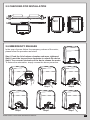
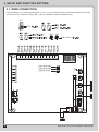
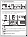
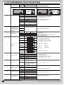
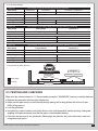
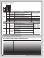
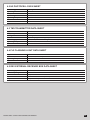
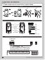
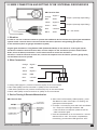
BOXER SERIES
SLIDING GATE OPENER
USER MANUAL
INDEX
1. GENER SAFETY PRECUATION
P.2
2. INSTALLATION
P.3
2.1 STANDARD INSTALLATION DEMONSTARTION
P.3
2.2 DESCRIPTION OF DEVICE
P.3
2.3 DIMENSION OF DEVICE
P.4
2.4 INSTALLATION OF GEAR MOTOR AND GEAR RACK
P.4
2.5 CHECKING FOR INSTALLATION
P.5
2.6 EMERGENCY RELEASE
P.5
3. SETUP AND FUNCTION SETTING
P.6
3.1 WIRE CONNECTION
P.6
3.2 TRANSMITTER MEMORIZATION
P.7
3.3 SYSTEM LEARNING AND LED DISPLAY
P.7
3.4 PROGRAMMABLE FUNCTION SETTINGS
P.8
3.5 TESTING AND CHECKING
P.9
3.6 SW2/SW6 SETTING
4. TECHNICAL CHARACTERIESTICS
P.10
P.10
4.1 TENICAL DATA SHEET OF BOXER SERIES
P.10
4.2 H2 PHOTOCELL DATA SHEET
P.11
4.3 TM3 TRANSMITTER DATA SHEET
P.11
4.4 FL2 FLASHING LIGHT DATA SHEET
P.11
4.5 RB1 EXTERNAL RECEIVER BOX DATA SHEET
P.11
5. ADDITIONAL INFORMATION
P.12
5.1 WIRE CONNECTION OF H2 PHOTOCELL (SAFETY BEAM)
P.12
5.2 WIRE CONNECTION AND SETTING OF RB1 EXTERNAL RECIEVER BOX
P.13
BOXER SERIES SLIDING GATE OPENER USER MANUAL
1
1. GENERAL PRECAUTION:
WARNING :
This user manual is only for qualified technicians who is specialized in installations and automations.
(1) All installations, electrical connections, adjustments and testing must be performed only after reading and
understanding of all instructions carefully.
(2) Before carrying out any installation or maintenance operation, disconnect the electrical power supply by
turning off the magneto thermic switch connected upstream and apply the hazard area notice required by
applicable regulations
(3) Make sure the existing structure is up to standard in terms of strength and stability
(4) When necessary, connect the motorized gate to reliable earth system during electricity connection phase.
(5) Installation requires qualified personnel with mechanical and electrical skills.
(6) Keep the automatic controls (remote, push bottom, key selectors…etc) being placed properly and away
from children.
(7) For replace or repair of the motorized system, only original parts must be applied. Any damage caused by
inadequate parts and methods will not be claimed to motor manufacturer.
(8) Never operate the drive if you have any suspect with what it might be faulty or damage to the system.
(9) The motors are exclusively designed for the gate opening and closing application, any other usage is
deemed inappropriate. The manufacture should not be liable for any damage resulting from the improper
use. Improper usage should void all warranty, and the user accepts sole responsibility for any risks there
by may accrue.
(10) The system may only be operated in proper working order. Always follow the standard procedures by
following the instructions in this installation and operating manual.
(11) Only command the remote when you have a full view of the gate.
TMT AUTOMATION INC. shall not be liable for any injury, damage, or any claim to any person or
property which may result from improper use or installation of this system.
Please keep this installation manual for future reference.
2
BOXER SERIES SLIDING GATE OPENER USER MANUAL
2. INSTALLATION:
2.1 STANDARD INSATLLATION DEMONSTARATION
4
3
3
1
2
1. 24Vdc Sliding motor
2. Transmitter
3. safety photo Sensor
4. Flashing light
2.2 DESCRIPTION OF DEVICE
g
c
d
f
b
e
a
a. Operation gear
b. Limit switch device
c. 24Vdc motor
d. Back-up batteries
BOXER SERIES SLIDING GATE OPENER USER MANUAL
e. Release device
f. Control panel
g. Terminals of devices
3
2.3 DIMENSTION OF DEVICE
2.4 INSTALLATION OF MOTOR GEAR AND GEAR RACK
1~
>25
50
>100
2m
25
4
BOXER SERIES SLIDING GATE OPENER USER MANUAL
2.5 CHECKING FOR INSTALLATION
SX
DX
NO
OK
2.6 EMERGENCY RELEASE
In the case of power failure for emergency release of the motor,
please follow the procedure as below:
Step1. Push the lid of release chamber and move rightward
Step2. Insert the key and turn clockwise to unlock the device
Step3. Turn counter-clockwise of the bar to release the motor
To restore the automation, simply reverse the above procedure.
Step2
Step1
Step5
BOXER SERIES SLIDING GATE OPENER USER MANUAL
Step3
Step6
Step4
Step7
5
3. SETUP AND FUNCTION SETTING:
3.1. WIRE CONNECTION
8
7
6
5
4
3
2
1
6
FL2
9
If the Led display is in normal performing refer to “4.2.1”, you can control the gate by either transmitters or the button
on the board: “UP”-clockwise moving, “SET”- stop and “DOWN”- Counterclockwise moving.
5
9
6
7
9
2
6
3
4
4
FL2 3
1
EXT+
EXT-
GND
Light
1
8
9
10
11
12
13
2
7
3
6
4
5
5
4
6
3
7
2
14
Close
Open
Stop
GND
Pb
Ph+
Ph2
Ph1
4
GND
5
+13.75
6
1
11
8
PB1, KS1=: 10
9
9
8
KS1
10
6
PB1
3
2
14
13
12
11
10
9
8
7
6
5
4
3
2
1
1
AC INPUT
6
LED1 Photocells
LED2 Photocells
LED3 RF Learn
5
4
3
2
1
AC INPUT
ON
1
2
3
4
5
6
ON
OFF
6
BOXER SERIES SLIDING GATE OPENER USER MANUAL
11
9
AC INPUT
6
3.2 TRANSMITTER MEMORIZING
Press “RF-learn” button for 2 seconds, and the Blue LED will be on; then press the transmitter (A) button;
The Blue LED will blink twice and stay on for 10 seconds then be off. And the remote memorize has completed.
A
B
14
13
1
LED1
LED2
LED3
Blue LED
2 Sec
1
Blue LED on the RF learning board
2
3
Blue LED
3.3 SYSTEM LEARNING AND LED DISPLAY
14
13
12
11
10
9
8
7
6
5
4
! CAUTION: Before proceeding to system learning, the transmitter memorizing process has to be completed.
LED1
To complete the system learning, follow
LED2the instructions below:
LED3 + “DOWN” for 3 seconds, and the LED display shows “LEA”
Step1: Press “SET”; then press “SET”
LED1
Stop2: Press button (A) on time, the LED display should shows “ARN”
LED2
Step3: The gate will goes to Auto-learning, please wait for the learning process to be completed
LED3
ON
OFF
Press
3 Sec
Push
1
2
3
ON
A
B
OFF
ON
Press
1~3 Sec
OFF
4
5
LED Display
6
Programmable Functions
“N-L”: The Boxer system learning is not done.
“RUN”: The Boxer system is in normal operation
To program, press SET button for 3 seconds, when the LED display change from RUN to F1,
press UP or DOWN to change function settings (F1 to FA). Then press SET to enter the sub
function within each group, press UP or Down to select sub functions and press SET for
confirmation.
“LEA”: Enter learning mode and then wait for learning instructions.
“ARN”: The system learning is in progress.
The Auto-learning process of gate moving:
“Gate open to the end- stop close to the end- stop.”
BOXER SERIES SLIDING GATE OPENER USER MANUAL
7
3
2
3.4 PROGRAMMABLE FUNCTION SETTINGS
LED Display
F1
Definition
Function
Value
Options of Gate
F1-0
Clockwise Opening
Opening direction
F1-1
Counterclockwise Opening
F1-0
F1-1
Clockwise
Opening
Gate Closed
F2
F3
F4
F5
Automatic Closing
The reactions of the
photocells/ safety
edge/ loop detector
when they detecting
obstacles
Motor Speed
Motor Over Current
Setting
F6
F7
Description
1. The function can adjust the dir
ection of gate opening.
2. The factory setting is "F1-1".
Pedestrian Mode
Gate Closed
F2-0
No automatic closing
F2-1
5 seconds
F2-2
15 seconds
F2-3
30 seconds
F2-4
45 seconds
F2-5
60 seconds
F2-6
80 seconds
F2-7
120 seconds
F2-8
180 seconds
Counterclockwise
Opening
1. This function can cause the gate
to close automatically after the
paused time.
2. The factory setting is "F2-0”:
No automatic closing .
F3-1
F3-2
Please refer to page 9,
F3 settings
1. The factory setting is “F3-3”.
F3-3
F4-1
F4-2
F4-3
F4-4
Speed 1
50%
70%
85%
100%
Speed 2
50%
60%
70%
80%
F5-1
Light
Heavy
F5-2
Light
Heavy
F5-3
Light
Heavy
F5-4
Light
Heavy
F5-5
Light
Heavy
F5-6
Light
Heavy
F5-7
Light
Heavy
F5-8
Light
Heavy
F5-9
Light
Heavy
F6-0
3 seconds
F6-1
6 seconds
F6-2
9 seconds
F6-3
12 seconds
F6-4
15 seconds
F6-5
18 seconds
F7-0
The flashing light blinks when
1. The function can adjust the running
speed of motor.
2. Speed 1: Motor full speed;
Speed 2: Speed during learning mode (of full speed)
3. The factory setting is “F4-4.”
1. The function can adjust the
running force of motor to be
compatible with the gate weight.
2. The factory setting is "F5-4".
3. The motor force value:
F5-1: 2A
F5-6: 7A
F5-2: 3A
F5-7: 8A
F5-3: 4A
F5-8: 10A
F5-4: 5A
F5-9: 13A
F5-5: 6A
4. As over current setting
1. The function can adjust the time
of opening partially.
2. The factory setting is "F6-1".
3. Press button B on the remote to
operate the pedestrian mode.
the gate starts to move.
Pre-flashing
F7-1
The flashing light blinks 3
seconds before the gate
1. The factory setting is "F7-0".
starts to move.
F8
F9
FA
8
F8-1
75%
Deceleration point
F8-2
80%
programming of total
F8-3
85%
travel distance
F8-4
90%
F9-1
100% System learning speed
F9-2
80% System learning speed
F9-3
50% System learning speed
F9-4
30% System learning speed
FA-0
No Auto - reverse
FA-1
1 second
FA-2
3 seconds
FA-3
Reverse to the end
Deceleration Speed
Auto - Reverse when
object impacted
1. The factory setting is “F8-4”.
1. The factory setting is “F9-4”.
1. The factory setting is “FA-3”.
BOXER SERIES SLIDING GATE OPENER USER MANUAL
● F3 function settings:
Logic F3-1
Gate Status
Closed
Open
Stop during moving
The reactions of the photocells when detecting obstacles
Photocell 2
Photocell 1
Photocell 1/ Photocell 2
Stop opening
No effect
Stop opening
No effect
Reloads automatic closing time
Stop opening
Reloads automatic closing time
Closing
No effect
Open
Locks and, on release, reverses to open
Opening
Closes the leaf
No effect
Locks and, on release, continues opening
Logic F3-2
The reactions of the safety edge/ photocell when detecting obstacles
Gate Status
Safety Edge
Photocell 1
Closed
Stop opening
No effect
Open
Reloads automatic closing time
Stop during moving
Stop opening/ closing
Reloads automatic closing time
Closing
Reverses to open for 2 seconds
Open
Opening
Reverses to close for 2 seconds
No effect
Logic F3-3
The reactions of the loop detector/ photocell when detecting obstacles
Gate Status
Closed
Loop Detector
Photocell 1
Open
No effect
Open
Reloads automatic closing time
Stop during moving
Open
Reloads automatic closing time
Closing
Open
Open
Opening
Open
No effect
●
The position of safety devices:
Loop Detector
Photocell 1
Photocell 1
or
Photocell 1 / Photocell 2
Safety Edge
Photocell
Photocell 2
3.5 TESTING AND CHECKING
Make sure the notices included in 1.1 General safety precaution “WARNINGS” has been carefully observed.
● Release the gearmotor with the proper release key.
● Make sure the gate can be moved manually during opening and closing phases with a force of max.
390N (40 kg approx.)
● Lock the gearmotor.
● Using the Key selector switch, push button device or the radio transmitter, test the opening, closing and
stopping of the gate and make sure that the gate is in the intended direction.
● Check the devices one by one (photocells, flashing light, key selector, etc.) and confirm the control unit
recognizes each device.
BOXER SERIES SLIDING GATE OPENER USER MANUAL
9
3.6 SW2/SW6 SETTING:
OFF
SW2
ON
OFF
Ph1
2
Ph2
3
Stop
4
D
5
C
6
SW6
Default
Device
1 – ON
3 – ON
Ph1
Photocell-1
Ph2
Photocell-2
Stop
4 – ON
5 – ON
6 – ON
Remote
Remote
None
2 – ON
SW6
ON
1
Default
Device
SW2
ON
2/4 Channel
Transmitter
SW2
OFF
2/4 Channel
Transmitter
Description
Remark
Switch to ON if Ph1 is not connected; Otherwise,
1 & 2 must switch to ON,
switch to OFF if Ph1 is connected
if Ph1 & Ph2 are not
Switch to ON if Ph2 is not connected; Otherwise,
connected to any devices
switch to OFF if Ph2 is connected
Switch to ON if “Stop (12)” is not connected; Otherwise,
switch to OFF if “Stop” is connected to any device
Setting with SW2
Setting with SW2
No function
Description (coordinate with remote)
Remark
With external device:
ON, Button B is pedestrian mode
SW6 4 - ON/OFF >
If connected with external device (EXT+/EXT-; 1/2),
SW6 4-ON; Button C on the remote can operation the device Button C - ON/OFF;
SW6 5 - ON/OFF >
If connected with external device (EXT+/EXT-; 1/2),
SW6 5-ON; Button D on the remote can operation the device Button D - ON/OFF;
OFF,Button B can operation the external device
If using a 2-channel
(EXT+/EXT-; 1/2)
remote and require the
OFF,SW6 4-ON; Button C is pedestrian mode;
Button B to operation
Button D no function
the external device,
OFF,SW6 5-ON; Button D is pedestrian mode;
switch the SW2 to OFF
Button C no function
4. TECHNICAL CHARACTERISTICS:
4.1 TECHANICAL DATA SHEET OF BOXER SERIES
Motor
Gear type
Peak thrust
Nominal thrust
Engine RPM
Absorbed Power
Power supply
Nominal input power
Maximum gate weight
Maximum gate length
Maximum operating current
Operating Temperature
Dimension LxWxH mm.
Weight
Speed
10
Boxer 500
Worm Gear
5500N
5000N
3800 RPM
60W
24 Vdc
3A
500kg
6 Meters
5.5A for Maximum 10 secs
-20oC~+50oC
250 X 170 X 265
8 kg
21.9 cm / sec
BOXER SERIES SLIDING GATE OPENER USER MANUAL
4.2 H2 PHOTOCELL DATA SHEET
Detection type
Operating distance
Response time
Input voltage
Operating Temperature
Protection class
Dimension
Through beam
30 meters
100ms
AC/DC 12~24V
-20℃~+60℃
IP66
59mm * 87mm * 38mm
4.3 TM3 TRANSMITTER DATA SHEET
Application
Frequency
Coding
Buttons
Power Supply
Operating Temperature
Dimension
Radio transmitter
433.92Mhz
Rolling code
2, for single-gate or dual-gate operation
3V with one CR2032 button type lithium battery
-20℃~+50℃
71.5mm * 33mm * 14mm
4.4 FL2 FLASHING LIGHT DATA SHEET
Application
Installation
Operating Temperature
Dimension
For outdoor use
Wall mounted vertically
-20℃~+50℃
85mm * 60.5mm * 40.5mm
4.5 RB1 EXTERNAL RECEIVER BOX DATA SHEET
Power Supply
Radio Frequency
Max. remote memorized
Dimensions
Output terminals
12V ~ 24V ac/dc
433.92Mhz
200pcs
106mm* 53mm* 20mm (L*W*H)
Output 1 & Output 2
BOXER SERIES SLIDING GATE OPENER USER MANUAL
11
5. ADDITIONAL INFORMATINO:
5.1 WIRE CONNECTION OF H2 PHOTOCELL (SAFETY BEAM)
Figure 5(1)
Figure 5(2)
Lens
1
2
3
4
Power Led
Indicator
2
3
4
Terminal Block
5
1
Power
Terminal Block
RX
RX
COM
N.C.
N.O.
GND
DC (12~24V)
Beam Alignmnet
Indicator
1
5
TX
2
1
2
GND
DC (12~24V)
TX
Figure 5(3)
CLOSE LOOP
1 2 3 4 5
1 2
3 4
11
Ph+
Pb
GND
12
13
14
Close
10
Open
9
Stop
8
Ph2
+13.75
6
Light
GND
7
GND
Ph1
8
EXT-
7
9
6
10
5
11
4
12
3
13
2
14
5
4
3
2
1
12
1
EXT+
DC (12-24V) GND NO NC COM
BOXER SERIES SLIDING GATE OPENER USER MANUAL
5.2 WIRE CONNECTION AND SETTING OF RB1 EXTERNAL RECIEVER BOX
RB1 Receiver Box
Orange
-Signal 1
Blue
-GND
Yellow
-Signal 2
Green
-GND
Red
-12V/24V
Black
-GND
Output 1 (Normally Open Relay)
Output 2 (Normally Open Relay)
12V - 24V AC/DC
1. Situation:
In order to use one 4 channel remote to operate with additional device besides the original gate automation
system. Install a receiver box to connect with the 2nd device (Such as swing/sliding gate opener)
or the 3rd device (Such as garage automation system)
Original gate automation: Using Button A & B (Pedestrian Mode) on the remote to control gate opener
2nd device: Install an external receiver box, connect output 1 to the 2nd device (such as another Boxer
Slider, shown as below) use button C on the same remote to control the 2nd device
3rd device: install an external receiver box, connect the output 2 to the 3rd device (such as garage door),
use the Button D now to operate.
2. Wire Connection:
Orange
-Signal 1
Blue
-GND
Yellow
-Signal 2
Green
-GND
Red
-12V/24V
Black
-GND
9
10
11
Ph+
Pb
GND
a. Orange cable (Signal 1) connect to terminal 10 (Pb) on the control board
b. Blue cable (GND) connect to terminal 11 (GND) on the control board
c. Red cable (12V/24V ac/dc) connect to terminal 9 (Ph+) on the control board
d. Black cable (GND) connect to terminal 11 (GND) on the control board
3. Device Testing & Remote Memorization
RB1 Receiver Box
BOXER SERIES SLIDING GATE OPENER USER MANUAL
a. After connect all necessary cables properly , press
Test Button to exam if the output 1 is working, the
gate opener should operate.
b. If Output 1 is functional, press and hold Learn Button
for 1 second, the LED light should be “ON”
* If the LED does not response, please check the
cable connection again
c. Press and hold Button C on the remote for 1 second
after the LED is “ON”. The remote completed the
memorizing process when LED light turns “OFF”
13
24V
Low Voltage
Durability
Key Release
Silence
EZ Instal
24V power supply
for great safety
Solid material apply
with lasting usage
Manual release device
with easy use and
highly protection
Worm gear application
give silence operation
Easy installation
and user friendly
interface
34100-085-D