1
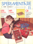
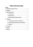
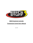
TORC: Automatic Transmission Controller
Sponsor: PAINLESS
Advisor: Professor Wright
Vanguard Engineering Group
February 22, 2008
Editor: David Cockley
____________________________
INTRODUCTION
The enthusiasm and passion some people feel toward their automobile is immense. Whether
someone builds a hot rod from the ground up or restores a timeless classic, they want the best
components they can afford in their pride and joy. Auto enthusiasts understand that the
transmission is part of the heart and soul of what makes a great performing ride. The advent of
the automatic transmission was a mechanical feat that made driving a vehicle a new
experience. Over the years, silicon has become cheaper, and increasingly capable electronic
control systems have arrived. These control systems have found their way into the after-market
auto industry as well. By controlling automatic transmissions with advanced electronics,
automobiles have improved and a new horizon of transmission control has opened up.
Vanguard Engineering Group’s design project will be to design and implement an electronic
automatic transmission controller. This transmission controller will be an after-market device
for the GM 4L60E transmission. The fact that this controller is electronic in nature means that
we can add features that might not have been included with the original 4L60E controller, and
It will be these features and the ability to be installed in an after-market fashion that make this
an attractive option for an enthusiast’s build.
There are some electronic transmission controllers currently on the market that are good
options for the GM 4L60E. One problem with these controllers is that they try to be good
solutions for as many controllers as possible. This means that if someone buys a transmission
controller for the GM 4L60E they also must inherently buy a controller for other transmissions
as well. This increases the cost of the device for someone that wants to use the controller on
solely the GM 4L60E. Our team’s goal is to be able to create a specialized controller just for the
GM 4L60E and cut down on some of the unnecessary cost of supporting multiple transmission
models.
PROJECT DESIGN
Problem Statement
The Vanguard Engineering Group is dedicated to optimizing transmission performance through
the development of an after-market electronic control system for automatic transmissions.
February 29, 2008
Project TORC
Page 1
Functional Requirements
Defining the functional requirements for this project is essential for defining the scope of the
project. The functional requirements contain the high level features Vanguard Engineering will
include in the pre-prototype
prototype and are the basis for all of the d
design
esign decisions. The main focus of
the TORC
ORC transmission controller project is to produce a device that controls the GM 4L60E
extremely well.. We do not want this controller to have so many feat
features
ures that it ends up being
just a satisfactory transmission ccontroller with a giant feature list. The controller will be an
excellent transmission controller that has a great set of features for controlling the 4L60E.
4L60E With
this mindset, the engineers of Vanguard Engineering have meticulously selected the features
they will provide and that they believe will make this device a premium controller.
controller
Functional Requirements
• Transmission Control Functionallity
• "Quick Logic" System
• Alternate Mode Operation
• End User Configurability
• Intuitive User Interface
• Rugged Packaging
• User-Friendly
User
Installation
Figure 1. Functional Requirements
Transmission Control Functionality – This device will properly operate and control the
functionality of the GM 4L60E automatic transmission using an electronic control system with
data from the necessary sensors.
“Quick Logic” System – The controller will contain shifting algorithms that provide for the
optimum performance of the transmission.
Alternate Mode Operation – A benefit of having an electronic transmission controller is that
you can create alternate transmission modes. This allows the user to be able to change the
shift timings to suit their current needs. Some basic modes that can be included are race mode,
mode
tow mode, and efficiency mode. This will change the timings to either increase a specific
performance point or increase the gas mileage of the car.
February 29, 2008
Project TORC
Page 2
End User Configurability – The end user will be able to configure certain aspects of the
controller using his home computer, some interface software, and a communication link
between the user’s home computer and the transmission controller. Some options that can be
controlled can range from custom timing modes to display information on an included LCD
display.
Intuitive User Interface – This product will also include a user interface allowing for the display
of statistics and diagnostic information. The user will also be able to select operating modes
and control features fluidly using this interface.
Rugged Packaging – Although the optimum placement will be on the inside of the automobile,
the device will have a rugged and attractive enclosure to prevent damage from neglect, abuse,
or improper placement.
User-Friendly Installation – It is imperative to the success of this device that it is easy for the
user to install. In order to support this ease of use, we will insure throughout our design that
we are taking the end user into account. We will also create excellent documentation and
installation instructions for the end user to insure the installation is easily done.
February 29, 2008
Project TORC
Page 3
Conceptual Block Diagram
The conceptual block diagram is a high level representation of the system that we will
implement for the transmission control. In the center, we have the enclosure containing the
microcontroller and the heart of the system. The microcontroller takes in data from the
necessary sensors and makes decisions as to which gear the automobile needs to be in by
outputting to the mechanical control portion of the transmission controller. We have also
included an overview of how the user will interface with the controller. When the controller is
installed in the vehicle, we will have some form of display and an interface for selecting the
current mode you want the transmission to be in such as race, tow, or economy. Also displayed
is the high level representation of how the user will be able to configure the controller using a
home computer.
r
se
U
e
cl ce
h i r fa
e
- V te
In In
User Configuration
Digital Inputs
Tr
Se
n
an
sm
so
rR
e
is and ad
si
in
on
gs
C
on
tro
l
C
on
fig
ur
a
tio
n
So
ftw
ar
e
Figure 2. Conceptual Block Diagram
February 29, 2008
Project TORC
Page 4
Functional Block Diagram
The functional block diagram covers the design of our system in a more detailed level. As
shown in this diagram, the PIC24FJ128GA010 is the microcontroller being used in our system.
This will be the controller that is used to control the transmission using the sensor data and
digital inputs that it receives.
Figure 3. Functional Block Diagram
In the block diagram, there are several inputs into the microcontroller. Most of these inputs
are sensors inputting the necessary data needed to determine proper shifting. Some of the
main sensors that are used to determine gear selection are engine speed, vehicle speed, and
throttle position. Using these inputs along with the shifter position digital input, we can select
the proper gear. Once the controller has selected the proper gear that the transmission needs
February 29, 2008
Project TORC
Page 5
to be in, it will output to the proper shift solenoids, which will mechanically force the
transmission into the proper gear.
Another portion of the transmission that we must control besides the gear selection is the
torque converter or TCC. One benefit of controlling the TCC is the ability to improve the gas
mileage of the car. This can be done by disabling the torque converter when it is no longer
needed, thus improving gas mileage.
Using this controller, we will also be able to include an LCD module for a useful and attractive
user interface. Along with this module, we will include a way for the user to select which
shifting mode they would like to use such as race mode or efficiency mode.
WORK PLAN
When attempting to design and complete a project of this scope, it is necessary to take into
account and plan for all the work that needs to be done. Breaking down the workload into
tasks and phases allows the project to run smoother and makes sure that the final goals are
met. In order to successfully breakdown the project into these different tasks, we use a tool
known as the Work Breakdown Structure. Using this tool, we have created five phases for our
design and implementation.
Figure 4. Work Breakdown Structure
Research
Research is an essential step to making sure that this project is a success. Although we have
experience in creating electronic systems, some knowledge of how automatic transmissions
function is essential. During our research, we will obtain a basic knowledge of the mechanics
behind an automatic transmission. Our main focus will be to determine the specifications of
the GM 4L60E and determine the various sensors that we will need to acquire data from. We
will also need to cover exactly what criteria we will use for shifting gears. This will help us
develop an algorithm that will determine the shift timings. Covering existing transmission
controllers will allow us to determine some of the basic functionality that must be included to
successfully control the transmission. The research phase will be broken down into several
February 29, 2008
Project TORC
Page 6
more tasks and sub-tasks, but at this phase it is important that every member of the team has a
substantial knowledge base of what will be done during our project. Along with researching the
actual functionality of an automatic transmission, we will research some of the tools that we
will use to control the transmission. This includes everything from the software development
environment to the PCB layout software we will be using.
Procurement
At first thought, procurement of hardware and other essential materials may seem like a minor
portion of the project. Whenever a project is done on a definite time table, as is our project,
the procurement of needed items can become a major headache. If we successfully plan ahead
of time for the necessary items, then we can improve our odds of not stalling our project
because we are waiting on parts to be delivered. The procurement phase can be broken down
into testing, hardware, software, and other tasks so that group members can take individual
ownership of acquiring the materials for a certain design element they are going to be in charge
of. Procurement will be done throughout the entire length of the project as parts are needed
and planning this part out will allow us to have efficient design and implementation stages.
Design
As far as our stakeholders are concerned, this is the most important portion of the work we will
be doing. Our team will most likely spend a majority of our time on this portion of the TORC
project. It is due to this fact that we must plan this phase well so that time is not wasted. This
phase is broken down into three sections, hardware, software, and the team website. The
hardware section of this phase includes all of the design work that needs to be done for the
hardware to function correctly. The main portions of the hardware design will include the PCB
layout, circuit design, wiring, and enclosure. The circuit design stage will include all of the
circuitry that needs to be made to interact with the transmission and the circuitry needed to
protect the controller from power surges and other protection needed when using the car’s
battery to power our device. Circuitry to power all of the devices at the proper voltage levels
will also be made. Our team may also need to include signal conditioning circuits for all of the
sensor readings that we will be doing from the transmission and the vehicle. Wiring will be a
big portion of this design process. It is paramount that the device is easy to install and can
connect to the transmission and vehicle power supply correctly. We will also need to design
wiring for the LCD user interface. As far as our enclosure is concerned, we must make sure that
it is durable and attractive and allows for ease of connection with our wiring.
Our team believes that much time will be spent on the software design of the transmission
controller. It is here where all the decisions will be made as to how we shift gears and the
timing of the shifting. We will need to design the architecture and flow of our program so that
February 29, 2008
Project TORC
Page 7
it is reliable and quick. An embedded system of this type must be robust and not fail. After the
architecture of our software is designed, we will begin designing the extra features such as the
shift mode selection and the user customization program. After a design task is completed, it
will usually be followed by an implementation stage where we will implement our designs.
Documentation
Documentation is another important phase of the TORC design project. We will need to
document the software and hardware design of this entire project. This is imperative so that
after the final prototype is completed the project can be continued if desired. Our team needs
to ensure that we include comments in our code as well as producing pseudo-code of our
algorithms and flow charts of our entire program.
We also need to include schematics and data on all of the circuitry that we design so that we
will have proper documentation of all the hardware.
Because we are including the ability for some user configuration, we will also need to include a
user manual for the device. Part of this documentation will include the development of
installation instructions and an instructional video.
Testing
Testing has been planned as a major portion of the TORC design project. In order to make sure
that our device has the capability of controlling a transmission, we must define a test setup that
will allow us to come to a successful conclusion. This will be done with a complete system test
of the final design and with testing the subsystems as we complete the implementations. In
testing the subsystems, it is also important that we test the user configuration mode well so
that we prevent user errors and allow for a user friendly experience.
Implementation
The implementation stage of our design will be the stage in which we construct and bring
together all of our designs into a final prototype. The implementation phase should follow
much of the same flow as the design phase only we are now implementing our design instead
of creating it. All of our circuits will first be prototyped and tested for functionality. After all of
our circuits have been created, we will then begin to make a PCB layout so that our design will
be efficient and concise. We must also implement our wiring and the connection of our
hardware to the transmission and automotive hardware. The implementation of the software
portion will be a large amount of our work. It is in this stage that we will implement the sensor
readings and control the shifting solenoids as well as the remainder of the transmission body
using our microcontroller. The actual user customization program and the communication
February 29, 2008
Project TORC
Page 8
between the user’s computer and the controller will be implemented at this stage as well. Th
The
implementation phase will be an exciting time where we will actually see some of the outcomes
of our designs and begin to create the final prototype.
MILESTONES
The project milestones are the high level goals that VEG has set to accomplish throughout the
course of this design project. Whenever a milestone is reached it will mark a significant stage of
completion
on in the development process. The final milestone is the only milestone that really
counts but setting several milestones will keep the project on track and allow for the
development of a better product.
Milestones
• Completion of Research
• Development Environment Established
• Hardware Design Specification
• Hardware Prototyping
• PCB Design and Implementation
• Transmission Control Software
• User Configuration Software
• Hardware Testing
• Software Testing
• Initial Prototype
• System Testing
• Pre-Production
Pre
Prototype
Figure 5. Milestones
Completion of Research
Although research will continue throughout the entire process, there is still a milestone when
all of the necessary research is done so that the team can begin to move to the design phase.
February 29, 2008
Project TORC
Page 9
Development Environment Established
Determining the software environment and the main hardware with which we will be working
with will be one of the first steps in starting the design phase.
Hardware Design Specifications Completed
At this milestone, we will have determined all of the sensors that we will be using and all of the
necessary circuitry and hardware needed to complete our design. Hardware specifications such
as wiring and harnesses will be completed for this milestone.
Hardware Prototyping Completed
After the specification we will piece together a rough prototype in which we can determine if
our designs will function as required. This milestone will be considered completed when all of
the hardware that we have specified for design has been implemented in a rough from.
PCB Design and Implementation Completed
The rough prototype will need to be developed into a PCB design, which will be our final
hardware schematic and design. This design will then be what we work with in testing and
software development for the remainder of the project.
Transmission Control Software Completed
This milestone marks the completion of the transmission control software. This will be all of
the software that is required to read the transmission sensors and control the operation of the
transmission successfully.
User Configuration Software Completed
The user configuration software is a separate entity from the transmission control software and
is a separate milestone. This will require a different style of programming that our group has
little experience with, and it will be a great accomplishment.
Hardware Testing Completed
Testing is a necessary phase in our process. When the hardware design that we have
implemented is done being tested, we will be one major step closer to an initial prototype.
February 29, 2008
Project TORC
Page 10
Software Testing Completed
It is necessary that our control software and configuration software is tested extensively before
the system testing is done. We may be testing this device on an actual transmission and
anything but minor errors could cause expensive damage. If the software is tested extensively,
then we can eliminate this chance and will have created a functioning program that we can
further test as a system.
Initial Prototype Completed
Combining all of the software and hardware that we have created into an initial prototype will
be a great achievement for our team. This will mark a closing to the majority of the design and
implementation work and the beginning of our system testing.
System Testing Completed
This testing stage will be the benchmark for determining whether or not our system is going to
function as required. When this stage is completed our only step will be to create a final
prototype and make sure that we have finished all of our work packages.
Pre-Production Prototype Completed
This milestone will mark the closing of our project. It is at this point that our team will have
created a device that is to our satisfaction and that we feel will please our stakeholders. It may
not mark the end of our team’s work, but it will be the end of all design and implementation for
this final prototype.
February 29, 2008
Project TORC
Page 11
DELIVERABLES
Deliverables are the elements that we will present to the project stakeholders to demonstrate
the growing value of this project. These are markers of achievements like milestones; only
these markers have specific value to the stakeholders and are actual tangible elements that
prove the design group is making progress. It is important that these deliverables are
presented throughout the course of the project so that the stakeholders can make informed
evaluations of the team’s progress.
Deliverables
• Parts List
• Functional Diagram
• Hardware Schematics
• PCB Layout Design
• Commented Source Code
• User Configuration Program
• Flow Chart and Algorithm Pseudo-Code
Pseudo
• Cost Analysis
• Test Plan and Test Data
• User's Manual and Installation Video
• Pre--Production Prototype
• Project Documentation and Final Report
Figure 6. Deliverables
Parts List
The parts list will contain in detail all of the parts that we use in our design. This is valuable to
our stakeholders so that they can determine
determine the cost of each part and will know which parts to
order to make more devices.
Functional Diagram
The functional diagram will be presented as a deliverable to the stakeholders. This functional
diagram will include the entire system schematic in a form that includes all of the components
and how they are connected together. The functional diagram is the best way to get quick
information on the system design of the TORC transmission controller.
February 29, 2008
Project TORC
Page 12
Hardware Schematics
The hardware schematics will include the pin layouts, connections, and circuit drawings of the
hardware we design. This in addition to the parts list will include all the information one would
need to replicate our hardware design.
PCB Layout Design
Our printed circuit board will contain all of the hardware necessary for our final prototype in an
efficient package. This PCB will allow for the concise and easy fabrication of our hardware and
will fit in the enclosure that we design.
Commented Source Code
In the creation of our controller, we will also create the source code for both the transmission
control and the user configuration software. This source code will contain the algorithms that
allow the controller to read the sensor data and control the shifting of the transmission’s gears.
User Configuration Program
The user configuration program is the software executable that the end user will use to
configure the controller. This software will be provided in its final form and will be able to be
used with the final prototype to customize certain features.
Flow Chart and Algorithm Pseudo-Code
Along with our final source code our team will also provide a flow chart and pseudo-code of the
source code explaining the algorithms used and how the program functions.
Cost Analysis
Included with the rest of the deliverables will be a cost analysis of the project. The cost analysis
will ensure that the cost of design and production fall in line with what the stakeholders deem
suitable for the TORC control system.
Test Plan and Test Data
Including the test plan and the test data in our deliverables will allow the stakeholders to see
how we have tested our design and what the results are from those tests.
User’s Manual and Installation Video
A copy of the user’s manual and installation video will be delivered to the stakeholders. This
manual will give a technical description of the device as far as the end user is concerned. This
February 29, 2008
Project TORC
Page 13
will allow them to gain an understanding of what the device does and a little bit of how it
functions.
Pre-Production Prototype
The final prototype will be one of the last deliverables. This deliverable will include our final
design along with its enclosure and all of the wiring necessary to install the controller to a GM
4L60E.
Project Documentation and Final Report
Along with the final prototype we will also include the final report and documentation covering
the entire scope of the design project and the final design.
RESOURCES
This table lists a basic estimation of what this project will cost. It breaks down each item and
lists the costs of these items
Item Description
Labor (3 persons x $25 x 40hr x 18 wk)
PCB Printing ($180.00 x 3)
IDE and Development Kits (2 x $200.00)
Wiring Harness Materials
LCD Displays
Microcontrollers
Miscellaneous Electronics
Test Equipment
System Enclosure
Miscellaneous Tools
Total
Estimated Cost
$54,000.00
$540.00
$400.00
$100.00
$50.00
$10.00
$100.00
$2000.00
$500.00
$500.00
$58,200.00
Figure 7. Resources
February 29, 2008
Project TORC
Page 14
TEAM QUALIFICATIONS
Figure 8. Team Hierarchy
Jacob MacElroy, Team Manager
Jacob MacElroy will function as the team manager for the TORC design project. Jacob has had
previous experience with this group of people on projects of smaller scope. Jacob will also be
assisting in both hardware and software and has previous real world hardware design and
verification experience through an internship with Cisco Systems, Inc.
Tyler Hollar
Tyler Hollar will function as the software engineering lead for TORC. Tyler has completed
eighteen hours of software development coursework at Texas A&M University giving him a
solid background. He also has specific experience with the C Programming Language on
embedded systems. Having experience in PHP, HTML, AJAX, CSS, and Dreamweaver Tyler will
also head up the website development for this design project.
Troy Vackar
Troy Vackar will function as the hardware specialist and test engineer for TORC. Troy has two
years of real world experience in both hardware and software with Texas Digital. Troy is also
the TORC team member most familiar with the after-market auto industry, having used aftermarket electronics in his personal vehicle.
February 29, 2008
Project TORC
Page 15