1
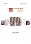
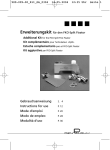
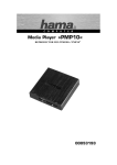
TotalCeph User Manual TotalCeph User Manual TotalCeph is an application designed to assist orthodontists in patient image management, cephalometric analysis, treatment planning and simulation. This user manual contains basic information about the usage of the application. Below you find the main sections of this manual. System Requirements Licensing Installation License Activation User Manual Support © 2012 Torc Software Ltd. www.torcsoft.com 1 TotalCeph User Manual System Requirements TotalCeph application can run on computers with Windows or Mac OS X operating systems. Windows System Requirements Windows version of TotalCeph application supports Windows XP with Service Pack 3 (Home Edition or higher), Windows Vista and Windows 7 operating systems. Minimum and recommended system requirements are listed as follows: Minimum System Requirements Windows® XP Service Pack 3 operating system 1 GHz Pentium IV processor 512 MB memory 1 GB available disk space Internet connection (for activation during setup) Recommended System Requirements Windows 7 operating system 2 GHz Core i5 processor 4 GB memory 50 GB available disk space Internet connection (for activation during setup) Mac OS X System Requirements Mac OS X version of TotalCeph application supports Mac OS X 10.6 and later 64-bit operating systems. Minimum and recommended system requirements are listed as follows: Minimum System Requirements Mac OS X 10.6 64-bit operating system 1 GHz Core Duo processor 512 MB memory 1 GB available disk space Internet connection (for activation during setup) Recommended System Requirements Mac OS X 10.7 64-bit operating system 2 GHz Core i5 processor 4 GB memory 10 GB available disk space Internet connection (for activation during setup) © 2012 Torc Software Ltd. www.torcsoft.com 2 TotalCeph User Manual Licensing TotalCeph has two different licensing models, Trial Version and Full Version. Trial version can be used for 30 days without a limitation and it’s totally free. Trial version can be downloaded from www.totalceph.com by signing up. Trial version stops working at the end of the trail period, so full version should be purchased. Full version license can be purchased from www.totalceph.com. After purchased, full version application can be used without a time or any other limitation. But full version license is an annual license, and should be renewed every year over the internet, free of charge. If licenses that are not renewed annually, application stops working, so the computer that TotalCeph runs on, should have an internet connection at least once in a year. There are special licensing alternatives for academic institutions. Please contact us at www.totalceph.com or email at [email protected] for more information about academic licensing. Renewing Full Version License: The application will warn user before annual license period ends (two weeks before license end date, on every application startup). License can be renewed easily and free of charge by pressing “Yes” on related warning message dialog inside the application. Attention: There should be an Internet connection on your computer during the license renewal process. © 2012 Torc Software Ltd. www.torcsoft.com 3 TotalCeph User Manual Installation Windows Installation For installation of TotalCeph on Windows Operating Systems please follow the steps listed below. Extract the zip file, which is downloaded from TotalCeph web site to any folder. From the folder you extracted the zip file, run setup.exe with administrator privileges. Installer Language Selection Windows is shown. Select the language you want to use during installation and press Ok. © 2012 Torc Software Ltd. www.torcsoft.com 4 TotalCeph User Manual TotalCeph Setup Wizard is shown. Press Next button. License Agreement is shown. Read License Agreement and press I Agree button. Choose Components Windows is shown. © 2012 Torc Software Ltd. www.torcsoft.com 5 TotalCeph User Manual Select the components and press Next button. Attention: If you are reinstalling or upgrading and want to keep present patient information uncheck TotalCeph Database. © 2012 Torc Software Ltd. www.torcsoft.com 6 TotalCeph User Manual Choose Start Menu Folder Windows is shown. Press Install button and start installation. If the installation is performed without any errors, the window displayed below is shown. Press Next button. Setup Completion Window is shown. © 2012 Torc Software Ltd. www.torcsoft.com 7 TotalCeph User Manual Press Finish button and finish installation. © 2012 Torc Software Ltd. www.torcsoft.com 8 TotalCeph User Manual Mac OS X Installation For installation of TotalCeph on Mac OS X Operating Systems please follow the steps listed below. Open TotalCeph.dmg file, downloaded from TotalCeph web site. From the folder opened run TotalCeph.mpkg setup package. The following window is shown. Press Continue button. Install destination selection window is shown. Press Continue button. For selection of components to install the following window is shown. © 2012 Torc Software Ltd. www.torcsoft.com 9 TotalCeph User Manual Select the components and press Continue button. Attention: If you are reinstalling or upgrading and want to keep present patient information uncheck TotalCeph Database. The disk usage for the installation of selected components is shown as given below. Press Install button. For gaining administrator privileges to install the following windows is shown. © 2012 Torc Software Ltd. www.torcsoft.com 10 TotalCeph User Manual Enter required information and press Install Software button. If installation is performed successfully then the following window is shown. © 2012 Torc Software Ltd. www.torcsoft.com 11 TotalCeph User Manual License Activation After finishing installation successfully, license activation process should be completed to be able to use TotalCeph application. In order to activate TotalCeph successfully, there should be an Internet connection on your computer. When TotalCeph is started for the first time, License Activation window is shown to start license activation process. All fields should be filled in the License Activation window, including the license key sent to you. Then, press Activate button. “License activation successful” message appears if the activation is successful, and then TotalCeph starts and Image storage folder selection window is shown. Otherwise failure reason is shown to the user as a warning and the application exits. If Cancel button is pressed, user is warned that application will not run unless License Activation is performed and then application exits. Note: All fields in the form above are required. © 2012 Torc Software Ltd. www.torcsoft.com 12 TotalCeph User Manual User Manual Detailed information about all windows present in TotalCeph application is given in this section. Main windows that form the application is listed below: TotalCeph Main Window Image Loader Window Image Explorer Window Cephalometric Analysis Window Treatment Simulation Window Superimpostion Window Image Comparison Window Combine Image Window In almost all windows of the application, tool windows’ layout and size can be modified by the user. Windows that have tool windows preserve layout and size information and displayed with the last used layout when reopened. This way each user can use the application with a window layout which is set up according to his/her needs. Attention: All measurements, simulations and image processing functions of TotalCeph application are provided to assist the doctors in treatment process. All diagnosis and possible treatments should be based on doctor’s knowledge and experience. Since TotalCeph does not provide any treatment that will replace doctor’s treatment, all treatment decisions are doctor’s own responsibility. © 2012 Torc Software Ltd. www.torcsoft.com 13 TotalCeph User Manual TotalCeph Main Window TotalCeph Main Window provides interface to listing of patient stored in the system, adding/deleting patient from system, application settings. It also provides access to Image Loader Window for adding images for the current patient and to Image Explorer Window for listing all images of the current patient. © 2012 Torc Software Ltd. www.torcsoft.com 14 TotalCeph User Manual Toolbar and Menu Items Toolbar Item Menu Item File New Patient Description To add a new patient, Patient Details window is shown. File Save Patient Changes made to current user are saved to the database. File Delete Patient Requests user confirmation to delete selected patient from the database. If confirmation is given selected patient is deleted from the database. TotalCeph application exists. File Exit Tools Options Options window is shown. Help Help Online help is shown. Help About TotalCeph Application version information is shown. - Image Loader Window is shown. - Image Explorer Window is shown. Patient List All patients stored in the database are listed with their first and last names. Patient list column headers can be used to sort the list items. When the application is run patient list is sorted in a way that the most recently created patient is listed on top and the least recently created patient is on the bottom of the list. List can be filtered by the keyword entered on the text field right above the list. Following attributes are shown for the selected patent. Personal Information o First Name o Last Name o Date of Birth o Gender Contact Information o Address o City o Zip Code o E-mail o Work Phone o Home Phone o Cell Phone Treatment Info o Status o Class Notes © 2012 Torc Software Ltd. www.torcsoft.com 15 TotalCeph User Manual Patient Details This window is used to add new patient to the database. Warning message is shown to the user when Save action is requested while mandatory fields such as First Name, Last Name, Date of Birth is missing. Attributes listed below can be specified for the new patient. Personal Information o First Name o Last Name o Date of Birth o Gender Contact Information o Address o City o Zip Code o E-mail o Work Phone o Home Phone o Cell Phone Treatment Info o Status o Class Notes Options Setting of application language, patient image storage folder and image series is set through Options window. © 2012 Torc Software Ltd. www.torcsoft.com 16 TotalCeph User Manual Application Language TotalCeph supports the following user interface languages: English Turkish Selected language will be active after the program is restarted. Image Storage Path This settings page is used to set image storage folder that contains the images of patient stored in the database patient images. When image storage folder is changed all files present in the old path is moved to newly selected path. While transferring files if the newly selected folder requires administrator privileges that the current user does not have, warning message is shown and the operation is canceled. In such cases, if you run the application with administrator rights image storage path change operation will be successful. Also when TotalCeph is run for the first time, the window seen below is shown to assist the user to select the image storage folder. Note: Folder Selection window is provided by the operating system, so its appearance may vary in different versions of Windows and Mac OS X operating systems. © 2012 Torc Software Ltd. www.torcsoft.com 17 TotalCeph User Manual Image Series Image Series settings page is used to set image series types. The following types are available by default: Initial Progress Final Post Treatment Users can add new image series types and decide which types are used. With button a new type is added. A type can be activated and deactivated by the user. With order of the types can be adjusted. © 2012 Torc Software Ltd. www.torcsoft.com 18 buttons TotalCeph User Manual Image Loader Window With this interface images can be imported and saved to the database for the cuurently selected patient. Patient Image Layout File System Tree View Thumbnail List TotalCeph supports standart image file formats (.bmp, .jpg, .png, .tif, etc.). Patient photos and X-Ray images should be in one of those file formats. © 2012 Torc Software Ltd. www.torcsoft.com 19 TotalCeph User Manual Patient Image Layout Three different layouts (X-ray, Image and Cast Mixed) are available in this interface. In order to layout images properly gudielines are provided. Blue guidelines are fixed and red guidelines can be moved by using the mouse. When mouse hovers over red guidelines mouse cursor is updated to show possible change directions. X-Ray Layout © 2012 Torc Software Ltd. www.torcsoft.com 20 TotalCeph User Manual Cast Mixed Layout Image Layout © 2012 Torc Software Ltd. www.torcsoft.com 21 TotalCeph User Manual Guidelines File System Tree View File System Tre View assists the user in selection of folder that contains images to import. When a folder is selection from tree view thumbnails of all image files with supported file formats are automatically generated and added to thumbnail list. Thumbnail List Thumbnails of image files with supported image formats existing in the selected folder are shown in this list. Thumbnails can be dragged via mouse to a desired image type inside patient image layout. Image preview is shown when user double clicks on a thumbnail image. © 2012 Torc Software Ltd. www.torcsoft.com 22 TotalCeph User Manual Image Settings Properties of the selected image from Patient Image Layout can be adjusted via this interface. Brightness/Contrast and zoom level of the image can be adjusted using this tool window. Zoom level adjustment and image placement can also be performed by using mouse. With left mouse button image placement, with right mouse button image rotation and with middle mouse button zoom level adjustment can be done. These operations are performed while specified button is pressed. Also user can take notes about images. Toolbar and Menu Items Toolbar Item Menu Item File Save Description Changed made to patient images are saved to database. File Delete Image Deletes the selected patient image. File Close Closes Image Loader Window. Tools Print To print Patient Image Layout Print Preview Dialog is shown. Tools Save as Image View Image Properties View Guidelines View Reset Guidelines Help Help Patient Image Layout is saved as image. To select file to save, file selection dialog is shown. Image Settings tool window is shown / hidden. Guidelines are shown / hidden. Guidelines are reset to default positions. Online help is shown. © 2012 Torc Software Ltd. www.torcsoft.com 23 TotalCeph User Manual Image Explorer Window Image Explorer Window displays all images of the currently selected patient in TotalCeph Main Window. It also provides access to cephalometric analysis, treatment simulation, superimposition, image combine, image compare, image copy and deletion. It is also possible to sort and filter the images. Sorting according to the image series is possible (Initial Post Treatment, Post Treatment Initial). Image Preview is displayed when user double clicks a thumbnail image. Toolbar and Menu Items Toolbar Item Menu Item Explorer Close Description Closes window. - Image Filter Menu is shown. View All Images All images of the current patient are shown. View Images for Cephalometric Analysis Only images that cab be analyzed are shown. View Images for Treatment Simulation Only images that are sutiable for treatment simulation are shown. View Sort By Series First to Last Sorts patient images according to series first to last. View Sort By Series Last to First Sorts patient images according to series last to first. Analyze Cephalometric Analysis Cephalometric Analysis Window is shown. For ceph, panaromic ceph, PA ceph, lateral photo, frontal photo, frontal photo (smile), right © 2012 Torc Software Ltd. www.torcsoft.com 24 TotalCeph User Manual occlusion, left occlusion, anterior occlusion, model upper occlusal, model lower occlusal, model right buccal, model left buccal, model anterior buccal images this button is enabled, otherwise it is disabled. Please refer to Cephalometric Analysis Window help section for more information. Enabled when a lateral ceph image is selected. Treatment Simulation Window is opened. Analyze Treatment Simulation Analyze Superimposition Tools Combine Images Tools Compare Images Enabled when a lateral ceph image is selected. Superimpostion Window, which enables user to superimpose different data of the patient, is opened. Enabled when a lateral ceph and a lateral photo image is selected together. Combine Image Window is opened. Enabled when any two images are selected together. Image Comparison Window is opened. Tools Copy Image Selected image is copied. (Can be pasted to other applications such as image editors.) Tools Delete Image(s) After getting confirmation from the user selected images are deleted from database. Tools Print Images(s) Prient Preview Dialog is shown to print selected images. Window Image Properties Image Properties tool window is shown / hidden. Help Help Online help is shown. Image Properties Properties of the selected image are displayed in this tool window. These properties are listed below: File Name, File Path, File Size, Image Dimensions, Image Type, Image Series, Date Taken, Notes. It is possible to change image type and series type using this interface. Supported image types are given below. Analysis is not possible for all types given in the list below. Some types are included for future versions. Lateral(right) Frontal Frontal Smile Upper Occlusal Lower Occlusal Right Occlusion © 2012 Torc Software Ltd. www.torcsoft.com 25 TotalCeph User Manual Anterior Occlusion Left Occlusion Over Jet Right Oblique Left Oblique Lateral Ceph PA Ceph Panoramic Rt. TMJ Lt. TMJ SMV Model Upper Occlusal Model Lower Occlusal Model Right Buccal Model Anteriror Buccal Model Left Buccal Left Hand Right Hand Cast Deciduous Dentition Cast Permanent Dentition Cast Mixed Dentition Compare Composition © 2012 Torc Software Ltd. www.torcsoft.com 26 TotalCeph User Manual Cephalometric Analysis Window Cephalometric Analysis Window enables user to analyze ceph, photo and cast model images by using landmarks. Results of the selected analysis method are shown both numerically and graphically. Supported Analysis Lateral Photo Epker & Fish Legan & Burstone Lip Rakosi Schwarz Tubingen Frontal Photo Divine Proportion Symmetry Tubingen Frontal Photo (smile) Golder Ruler Lateral Ceph Aachen Bergen/Hasund Berlin Bern © 2012 Torc Software Ltd. www.torcsoft.com 27 TotalCeph User Manual Burstone Craniofacial Burstone Profile Clark Correlative Clark Linear Denture Frame Downs Downs (International) Dual Plane Epker & Fish Frankfurt Freiburg Harvold Heidelberg Holdaway Innsbruck Jarabak Dental Jarabak Skeletal Legan & Burstone Lip Mc Gann Mc Laughlin Mc Namara Munster Oslo Profile Rakosi Incisor Rakosi Metric Rakosi Sagittal Rakosi Vertical Ricketts Ricketts Short Riedel Roth - Jarabak Sassouni Schmuth Schwarz Craniometric Schwarz Gnathometric Steiner Tweed Zurich PA Ceph Munster Ricketts Panaromic Ceph Implant Survey Cast Deciduous Dentition Tubingen © 2012 Torc Software Ltd. www.torcsoft.com 28 TotalCeph User Manual Cast Permanent Dentition Arc Length Korkhaus Muhlberg Linder & Harth Lundstrom Pont Supporting Zone Symmetry Weise Cast Mixed Dentition Ballard-Wylie Berendonk Carey Droschl Huckaba Korkhaus Linder & Harth Muhlberg Muller Pont Index Tanaka Tonn Weise Landmarks Landmarks tool window contains analysis list view, landmarks list view (list of landmarks that should be located by user, or located by the application using located landmarks) and a sketch view that guides the user in location landmarks. Landmark list view is automatically updated when analysis selection is changed. Although they are applied to same type of images, required landmarks for each analysis may vary. Landmars already located are preserved when analysis selection is changed. When a landmark is selected from the landmark list, all measurements affected directly or indirectly by the selected landmark is highlighted. Also when right mouse button is clicked on a selected landmark, a menu is shown which enables to delete the selected or all landmarks in the list. To guide the user in locating landmarks a sketch view is shown. All landmarks are displayed with blue color and only currently selected landmark is displayed with red color in sketch view Viewer Viewer displays all graphical objects that are related with the landmarks, mesaruements, templates and analysis graphics. To locate a landmark on an image first a landmark should be selected from landmark list. When viewer is in “Place Landmarks” mode, landmarks are placed by clicking left mouse button once. Landmarks that are located before can be relocated by using left mouse button when viewer mode is “Select/Move”. When position of a landmark is changed all reletad measurements, graphics and templates are automatically updated. Similarly when analysis selection is changed analysis graphics are automatically updated. Templates are automatically positioned according to the landmarks’s positions. To avoid miscalomputations these templates should be manually fine tuned © 2012 Torc Software Ltd. www.torcsoft.com 29 TotalCeph User Manual by the user. Also in “Select/Move” mode when user clicks a template, selected template become activated and control points of the Bezier curve forming the template become visible. Active Template Calibration Settings Measurememts defined in analysises that compute distance between certain positions require image to be calibrated. For calibrating the image two points should be placed with extacly calibration segment length distance from each other. Default calibration segment length is defined as 100 milimeters. User can change calibration segment length for current image using Calibration Settings tool window. Results Measurements related with the selected analysis and clinical norm values of these measurements are shown in this tool window. © 2012 Torc Software Ltd. www.torcsoft.com 30 TotalCeph User Manual Toolbar and Menu Items Toolbar Item Menu Item Tracing Save Tracing Print Report Description Saves tracing data to database. Tracing includes landmark postions, template defintions and data related with the selected analysis. Shows Report Preview dialog with current tracing and measurements. Tracing Close After promting user for saving data closes Cephalometric Analysis Window. Layer Landmarks Shows / hides landmarks layer in viewer. Layer Templates Shows / hides templates layer in viewer. Layer Graphic Shows / hides analysis graphics layer in viewer. View Zoom In Zooms in to the image in viewer. View Zoom Out Zooms out from the image in viewer. View Fit to Window Adjusts the zoom level of the viewer so that all objects are visible. View Zoom to Actual Size Adjusts the zoom level of the viewer so that image is shown with its real resolution. View Magnifier View Mode Pan View Mode Select/Move View Mode Place Landmarks Image Adjust Brightness/Contrast Image Grasyscale Inversion Image Histogram Equalization Shows / hides cursor following magnifier. Sets viewer mode to pan mode. When pan mode is active you can pan with both left and right mouse buttons pressed, without placing landmarks or editing tracing. Sets viewer mode to select mode. When select mode is active you can select and relocate landmarks or select templates and reshape them by moving Bezier curve control points. Sets viewer mode to edit tracing mode. When edit tracing mode is active you can position landmarks with left Mouse button and pan with right mouse button. Activates brightness/contrast adjustment mode. With left mouse button pressed, by moving mouse up and down brightess can be increased and decreased, also by moving mouse right and left contrast can be increased and decreased. Performs grayscale inversion to all pixels of the image. Black pixels become white and white pixels become black. Performs histogram qualization process. This will enhance the image with low contrast and assist use to distinguish pixels easily. © 2012 Torc Software Ltd. www.torcsoft.com 31 TotalCeph User Manual Image Smooth Image To suppress the noise in image, smoothing is performed. Image Sharpen Image To enhance edges in the image, sharpening is performed. Image Shaded Relief Produces a shaded relief from image to help user in visualizing structural components of image. Image Reset Changes Görüntüye uygulanan tüm işlemler kaldırılarak görüntü orijinal halı ile gösterilir. Window Results Window Calibration Settings Help Help Results tool window is shown / hidden. Calibration Settings is opened. Online help is shown. © 2012 Torc Software Ltd. www.torcsoft.com 32 TotalCeph User Manual Treatment Simulation Window Treatment Simulation Window provides interface to perform treatment simulation on already analyzed lateral ceph images including soft tissue simulation. During simulation analysis results of original image and analysis results of simulation image can be compared bothh visually and numerically. To open treatment simulation window a lateral ceph image should be selected from Image Explorer Window. If positions of all required landmarks are not set for the selected image user is warned and treatment simulatşon window is closed. © 2012 Torc Software Ltd. www.torcsoft.com 33 TotalCeph User Manual Viewer Original and simulation images and all graphic objects related with these images are displayed in this component. Visibility of images and layers are controlled by the toolbar and menu items. If loaded lateral photo can also be displayed together with lateral ceph image. Transparency of images can be adjusted by slider control above images. Profile template of simulation image can be adjusted as in Cephalometric Analysis Window. Selected region (either from region tree view or from viewer) is displayed with different color. Rotation center of selected region is also displayed with an icon on top of region. © 2012 Torc Software Ltd. www.torcsoft.com 34 TotalCeph User Manual Regions Region definition, positioning regions can be performed using this tool window. This interface consists of Region Tree View, Edit Regions, Position Regions and Region Displacement components. Edit Regions This componenet provides tolls for creating and editing regions which are used in simulation. Tool Setup Regions Create Region Description To setup region definition Setup Regions dialog is shown. Using this dialog user can set how maxilla, mandible, incisor and molar tooth is defined. Maxilla and mandible can de defined as independent regions. Also with the decision of user insicor and molar tooth can be defined as independent regions or bound to maxilla and mandible main regions. When Setup Regions is shown user is warned that current region definition will be reset. To create and add a new main region, template list view is shown. If user does not select an item from the list an empty region is created. With Add Sub Region sub regions can be added to the new main region. Deletes selected region from Region Tree View. All transformation applied on this region is reset to original state. Delete Region Current mode is set to add sub region to the selected main region from region tree view. Sub regions can be added by using templates or manually from image. Add Sub Region Remove Sub Region Current mode is set to remove sub region from the selected main region from region tree view. To remove sub regions freehand region selection or select region from template should be active. © 2012 Torc Software Ltd. www.torcsoft.com 35 TotalCeph User Manual Freehand Region Selection Select Region from Template Create Cut Delete Cut Set Center of Rotation This tool is user to add sub region to or remove sub region from selected main region. Region selection is performed by moving left mouse button while it is pressed and selection is finalized when mouse button is released. This tool is user to add sub region to or remove sub region from selected main region. When add sub region mode is active template list populated with unused templates is shown. And when remove sub region mode is active template list populated with used templates in selected region is shown. When removed all transform applied to sub region is reset. Create Cut mode is activated. This tool is enabled when a region with no cuts is selected from region tree view. To create a cut on original image cut line should be defined with left mouse button while left mouse button is pressed. After cut process is performed region is divided into two regions. These regions can be moved independently and also they can be moved together. When a region with a cut is selected from region tree view cut line is displayed on original image with a gray line. This tool is enabled when a region with a cut is selected from region tree view. When delete cut operation is performed two sub regions forming the main region is merged and relative transform of sub regions is reset. Mode is set to setting center of rotation of selected region from region tree view. Selection of rotation center is performed with left or right mouse button on original image. When left mouse button is used nearest landmark to click position is selected and when right mouse button is used clicked position is selected. © 2012 Torc Software Ltd. www.torcsoft.com 36 TotalCeph User Manual Position Regions Provides transform, rotate and reset tools for selected region from region tree view. Tool Description Selected region is rotated clockwise around region rotation center. Rotate Clockwise Selected region is rotated counter clockwise around region rotation center. Rotate Counterclockwise Selected region is moved one defined displacement unit to left. Move Left Selected region is moved one defined displacement unit to right. Move Right Selected region is moved one defined displacement unit to down. Move Down Selected region is moved one defined displacement unit to up. Move Up Set Line Start Set Line End Mode is set to setting of displacement line start point. When this mode is active with a left mouse button click on original image sets displacement line start point. This point is displated with a yellow circle on original image. Mode is set to setting of displacement line end point. When this mode is active with a left mouse button click on original image sets displacement line end point. This point is displated with a yellow circle on original image. When both end points of displacement line is set line is dispyed with a yellow line. Selected region is moved one defined displacement unit to start point of displacement line. Move To Start Selected region is moved one defined displacement unit to end point of displacement line. Move To End Selected region is moved one defined displacement unit orthogonally up from displacement line. Move Orthogonally Up Selected region is moved one defined displacement unit orthogonally down from displacement line. Move Orthogonally Down Reset Region All transform operations perfomed on selected region are reset. If selected region is a sub region of a region with cut, only relative transform of sub region is reset. Reset all regions in region tree view to initial positions and transforms. Reset All Regions © 2012 Torc Software Ltd. www.torcsoft.com 37 TotalCeph User Manual Region Displacement Total and relative displacement data of selected region is displayed in this interface. Displacements are measured acccroding to the displacement unit and coordinate system defined in Options tool window. Options Analysis usage, displacement and rotation unit definition and coordinate system definition can be done via this interface. Graphics objects are automatically updated when current analysis selection is changed. Similarly graphics in Compare Tracings viewer and measurements in Compare Results tool window are automatically updated upon analysis change. Default displacement change unit is 1 mm and its maximum is defined as 100 mm. Default rotation change unit is 1 degree.To defined coordinate system which is used in computing displacements of regions and landmarks several options are available. Image coordinate system can be used directly. Also by selecting two landmarks one axis of coordinate system can be defined, so that other axis is perpendicular to it. Direction of the positive axis is also selectable by user. © 2012 Torc Software Ltd. www.torcsoft.com 38 TotalCeph User Manual Soft Tissue Controls how soft tissue simulation is performed. In soft tissue simulation rules defining how changes of landmarks in horizontal and vertical axis will affect landmarks on profile template is used. Standard rule set is provided with the application. Also user can define new rule sets using this interface. Since a landmark can be affected by more than one landmark, rules are applied according to their weights. Rules can be defined in chains. For example landmark a affects landmark b and landmark b affects landmark b. However cyclic rule definition is prevented and user is warned to fix rule set when such cycles are detected. Tool Activate AutoUpdate Description When this item is checked rules are applied automatically when regions are transformed. Adds a new rule to the end of rule set. Delets selected rule from the rule set. To save rule set soft tissue rule set list is shown. User can select and exisiting rule set to update (except standard) or create a new rule set by selecting last item from list. Names of list items can be changed by user. To load an existing rule set soft tissue rule set list is shown. If a rule set is selected from the list shown all unsaved changes made to current rule set will be discarded. Apply Applys rule set. Cancel Cancels changes made to the rule set. Unspecified Points Update Simulation of soft tissue landmarks with no related rules is defined via this interface. By using maximum distance for 100 % effect and no effect distance and near landmarks simulated with rules soft tissue landmarks wih no related rules are simulated. Changes from near landmarks within maximum distance for 100 % effect are applied directly. This effect is linearly decreased to null till no effect distance is reached for near landmarks. © 2012 Torc Software Ltd. www.torcsoft.com 39 TotalCeph User Manual Compare Images Original and simulation images are superimposed in this viewer. Transparency of the images can be adjusted using the slider control inside the toolbar of this tool window. Toolbatr Item Description Zooms in to scene in Compare Images viewer. Zooms out of the scene in Compare Images viewer. Adjusts the zoom level of Compare Images viewer so that scene is fit inside. © 2012 Torc Software Ltd. www.torcsoft.com 40 TotalCeph User Manual Compare Tracings Tracings from original and simulation images are superimposed on this viewer. It is possible to show / hide analysis graphics. Toolbar Item Description Zooms in to scene in Compare Tracings viewer. Zooms out of the scene in Compare Tracings viewer. Adjusts the zoom level of Compare Tracings viewer so that scene is fit inside. Shows / hides analysis graphics inside the scene. © 2012 Torc Software Ltd. www.torcsoft.com 41 TotalCeph User Manual Compare Landmarks Horizontal, vertical and total displacement values are listed according to the coordinate system defined in Options tool window. Sorting is possible when left mouse button is clicked on the desired column title. Compare Results Analysis results together with clinical normal values are listed for both original and simulation images. Toolbar and Menu Items Toolbar Item Menu Item Simulation Save X-Ray Simulation Simulation Save Photo Simulation Simulation Load Photo Simulation Compute Result Description X-ray simulation result image, analysis results and all landmark, tracing and template data is saved to the database. Is lateral photo is used during simulation photo simulation result image, analysis results and all landmark, tracing and template data is saved to the database. To load lateral photo image selection view is shown. This tool when lateral photo is loaded and successfully registered to X-Ray image. Computes © 2012 Torc Software Ltd. www.torcsoft.com 42 TotalCeph User Manual Simulation Print Report Simulation Close possible effects of transforms of regions to the soft tissue and computes a possible post treatment simulation result of patient’s lateral photo. Shows Report Preview dialog with original and simulation tracing, images and measurements. Treatment Simulation Window is closed. View Zoom In Zooms in to the image in viewer. View Zoom Out Zooms out from the image in viewer. View Fit to Window Adjusts the zoom level of the viewer so that all objects are visible. View Zoom to Actual Size Adjusts the zoom level of the viewer so that image is shown with its real resolution. View Magnifier Shoes / hides cursor following magnifier. View Layer Landmarks Shows / hides landmarks layer in viewer. View Layer Templates Shows / hides templates layer in viewer. View Layer Graphics Shows / hides analysis graphics layer in viewer. View Layer Regions Shows / hides region layer in viewer. View Layer Image Shows / hides X-ray and photo images in viewer. Compare Landmarks Compare Landmarks tool window is shown / hidden. Compare Tracings Compare Tracings tool window is shown / hidden. Compare Results Compare Results tool window is shown / hidden. Compare Images Compare Images tool window is shown / hidden. Tools Regions Tools Soft Tissue Tools Options Help Help Regions tool window is shown / hidden. Soft Tissue tool window is shown / hidden. Options tool window is shown / hidden. Online help is shown. © 2012 Torc Software Ltd. www.torcsoft.com 43 TotalCeph User Manual Superimpostion Window This interface enables user to superimpose different tracings from different lateral ceph images of the same patient and compare them. This tool is enabled when a single lateral ceph image is selected from patient image list in Image Explorer Window. Superimposition This component displays landmarks, templates and analysis graphics on reference image according to selection of tracings. Selection of tracings to display is chose from Options tool window. Display of graphics objects from selected tracings is adjusted using toolbar and menu items. © 2012 Torc Software Ltd. www.torcsoft.com 44 TotalCeph User Manual Reference Image Reference image used in superimposition is displayed in this interface together with tracing graphics. Toolbar Item Description Zooms in to scene in Reference Image viewer. Zooms out of the scene in Reference Image viewer. Adjusts the zoom level of Reference Image viewer so that scene is fit inside. Measurements Results of analysis measurement of selected tracings are displayed in this interface. © 2012 Torc Software Ltd. www.torcsoft.com 45 TotalCeph User Manual Options Analysis Analysis displayed in Superimposition viewer, Reference Image viewer and Measurements tool window is selected using this interface. Upon change of analysis selection all related graphical and numerical data is automatically updated. Registration Selection landmarks used in registration of different tracings is performed via this interface. To register tracing graphics o contact landmark and and direction landmark should be selected. To have a successful registration landmarks surveyed on all tracings should be selected. Select Tracing Tool Select All Description Selects all tracings so that related graphics are displayed on viewers and tabular views. Clear All Clears all selection of tracings. When user double clicks with left mouse button to color column of tracings list to select the color of related tracing graphics in Superimposition viewer color selection window is shown. (Note: Color Selection Window is provided by the operating system so its appearance is different in Windows and Mac OS X versions.) © 2012 Torc Software Ltd. www.torcsoft.com 46 TotalCeph User Manual Toolbar and Menu Items Toolbar Item Menu Item File Save as Image Description Save scene in Superimposition viewer to the database as an image with comparison image type. Shows Report Preview dialog with selected tracings. File Print Report File Close Superimpostion Window is closed. View Zoom In Zooms in to the image in viewer. View Zoom Out Zooms out from the image in viewer. View Fit to Window Adjusts the zoom level of the viewer so that all objects are visible. View Layer Landmarks Shows / hides landmarks layer in viewer. View Layer Templates Shows / hides templates layer in viewer. View Layer Graphics View Layer Transform Lines Shows / hides analysis graphics layer in viewer. Shows / hides transform lines which show horizontal and vertical displacements of reference image landmarks and landmarks of other tracings. Shows / hides X-ray image in viewer. View Layer Image Window Superimposition Superimposition viewer is shown / hidden. Window Measurements Measurements tool window is shown / hidden. Tools Reference Image Tools Options Help Help Reference Image tool window is shown / hidden. Options tool window is shown / hidden. Online help is shown. © 2012 Torc Software Ltd. www.torcsoft.com 47 TotalCeph User Manual Image Comparison Window User can compare two images horizontally, vertically or in single viewer. This interface can be used to compare pore and post treatment images to assess treatment results visually. Toolbar Item Description Lay out is set to horizontal. Lay out is set to vertical. Images are displayed on single viewer. Tranparency of images can be adjusted using the slider control inside toolbar. Horizontal Layout: © 2012 Torc Software Ltd. www.torcsoft.com 48 TotalCeph User Manual Vertical Layout: © 2012 Torc Software Ltd. www.torcsoft.com 49 TotalCeph User Manual Single Viewer: © 2012 Torc Software Ltd. www.torcsoft.com 50 TotalCeph User Manual Combine Image Window User can map lateral ceph and lateral photo images using this ınterface. Image mapping can be performed using landmarks that exist in both images or by manually selecting corresponding points on both images. Viewer Combinded images are displayed in this viewer. Reference X-ray X-ray image used in combination is displayed in this viewer. © 2012 Torc Software Ltd. www.torcsoft.com 51 TotalCeph User Manual Toolbar Item Description Zooms in to scene in Reference Image viewer. Zooms out of the scene in Reference Image viewer. Adjusts the zoom level of Reference Image viewer so that scene is fit inside. Selected part of reference image to be used in combination is reset to whole image. Selection graphic is removed from viewer. Reference Photo Lateral photo image used in combination is displayed in this viewer. Toolbar Item Description Zooms in to scene in Reference Image viewer. Zooms out of the scene in Reference Image viewer. Adjusts the zoom level of Reference Image viewer so that scene is fit inside. Selected part of reference image to be used in combination is reset to whole image. Selection graphic is removed from viewer. © 2012 Torc Software Ltd. www.torcsoft.com 52 TotalCeph User Manual Options Registration Tool Manual Landmark Manual Landmark Description Interaction mode on reference image viewers is set to manual mapping start point setting mode. When checked mapping start point is selected from landmark combo box. Interaction mode on reference image viewers is set to manual mapping end point setting mode. When checked mapping end point is selected from landmark combo box. Area Selection User can set current area selection mode to select parts of images from reference image viewers. Choices are listed below: Freehand Rectangle © 2012 Torc Software Ltd. www.torcsoft.com 53 TotalCeph User Manual Rounded Rectangle Ellipse Tracing Selected analysis graphics are displayed on patient image in viewer. To view these graphics image mapping should be finished and graphics display options should be cheked from toolbar or menu. Show Photo Graphics and Show X-ray Graphics options control whether analysis graphics from related images are displayed on combined image or not. Since two profile templates are available when image mapping is finished use can select which profile template to display on combined image. Toolbar and Menu Item Araç Çubuğu Öğesi Menü Öğesi File Save Image Açıklama Combined image in viewer is saved to the database with combine image type. File Save Mapping Registration data that maps two images is saved to the database. When these two images are opened again with Combine Image Window this registration data will be used automatically to map these images. This data is also used when loading a letaral photo in Treatment Simulation Window. Combine Image Window is closed. File Close View Zoom In Zooms in to the image in viewer. View Zoom Out Zooms out from the image in viewer. View Fit to Window Adjusts the zoom level of the viewer so that all objects are visible. View Layer Landmarks Shows / hides landmarks layer in viewer. View Layer Templates Shows / hides templates layer in viewer. View Layer Graphics View Layer Image - - Shows / hides analysis graphics layer in viewer. Shows / hides X-ray image in viewer. Interaction mode on reference image viewers is set to manual mapping start point setting mode. Left user clicks with left mouse button on reference image, click point is set to mapping start point of related image. Interaction mode on reference image viewers is set to manual mapping end point setting mode. Left user clicks with left mouse button on reference image, click point is set to mapping end point of related image. © 2012 Torc Software Ltd. www.torcsoft.com 54 TotalCeph User Manual - Tools Reference Photo Interaction mode on reference image viewers is set to area selection mode. Selected are with left mouse button pressed is set to selection area of related image. Reference Photo tool window is shown / hidden. Tools Reference X-ray Reference X-ray tool window is shown / hidden. Tools Options Help Help Options tool window is shown / hidden. Online help is shown. © 2012 Torc Software Ltd. www.torcsoft.com 55 TotalCeph User Manual Support For support requests you can visit www.totalceph.com web site or contact us via [email protected] e-mail address. © 2012 Torc Software Ltd. www.torcsoft.com 56