1
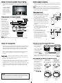
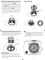
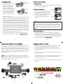
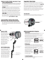
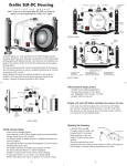
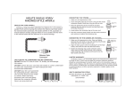
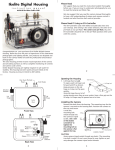
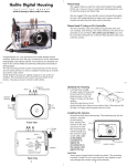
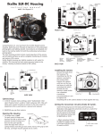
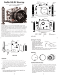
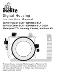
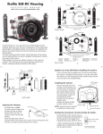
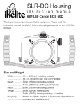
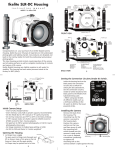
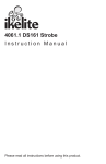
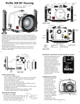
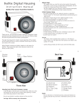
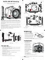
Setting the Conversion Circuitry Strobe ID Switch.
On the bottom of the camera tray is a switch for setting the DS
Substrobe ID. Set the switch to the Model of DS Substrobe being
used.
• When using dual
strobes of different
models such as a
DS51 and a DS125,
set the ID switch to
DS51 or the smaller
strobe.
DS 50/51
80
125
DS 160
Set
DS Substrobes
to TTL Mode
200
Flash Connection for External Strobes
External Strobe Connector
When using an
and Waterproof Cap
external strobe,
O'ring
connect the
Housing Back
housing hotshoe
connector. Slide the
connector into the
hotshoe mount on
Hot Shoe
the camera, from the
Connector
back of the camera
as shown. Slide the
Mounting
connector forward
Tray
until it stops. This
can be done before
or after the camera is
secured with the
mounting bolt.
NOTE: Make sure
the hotshoe is pushed all the way forward on the camera mount.
5
Closing the Housing (cont.)
Once the camera is installed and the lid snaps have been closed,
make sure the lid-snap lock tab is vertical to the lid-snap, and is
properly engaged. You should be unable to open the lid-snap
when the tab is properly engaged and in it’s locked position.
Make sure the remaining housing controls are returned to their
proper operating position. Check operation of all housing
controls.
Double check - Once the housing is closed, check the o’ring seal.
Note that the gap between the housing back and the housing
should be even all the way around.
Look through the clear plastic back at the o’ring. You should see
a darkened area where the o’ring is compressed against the
housing back. If you do not see an even black compression seal
all the way around the back, open the lid snaps, reseat the housing back, and then close the lid snaps. Visually check the seal
again.
Caution:
Do not remove the External Strobe Connector waterproof cap
unless an external sync cord is going to be plugged in. Do NOT
remove waterproof cap or sync cord underwater.
7
Installing Camera in Housing
Before installing the camera, pull out on the controls in the front
section of the housing. This will allow the camera to slide in more
easily.
NOTE: The AEL-AFL, Info, and Fn controls must be pulled all the
way out. After you insert the camera into the housing front, carefully push in the the controls so that they will properly operate
the corresponding camera buttons.
Closing the Housing
1. Place housing face down in your lap.
2. Check to see that there is an o’ring
on the housing back that is clean
and in it’s proper location.
3. Guide the back onto the housing.
The o’ring should touch the housing
all the way around. There should
be an even gap all the way around
between the housing and the hous- housing
ing back.
4. Lift the lid snaps so they are
extended and place the lid snap into
the corresponding hook on the
housing back.
5. To close the housing, push
down on the lid snaps until
even gap
they snap into place . Lid
all 4 sides
snaps on opposite sides of
the housing should be closed
at the same time. Be sure they
are down far enough to engage
housing
Figure B-Type 2 Lens
the lid-snap lock.
housing back
o’ring
housing back
o’ring
6
Figure A-Type 1 Lens
Preparing to Install Zoom Clamp & Gear Sleeve
Determine the type
of lens being used
on the camera.
Type 1 Lenses have
a lens opening that
is NOT larger in
diameter than the
zoom ring. (Fig. 1).
lens
opening
zoom
ring
Type 1 lens
(Figure 1)
bayonet
mount
Type 2 lens
(Figure 2)
Type 2 Lenses have a lens
opening that IS larger in diameter than the zoom ring. (Fig. 2).
Zoom Clamps & Gear Sleeves Included with Housing
F
There are 2Figure
different
Zoom Clamps and
Gear Sleeves
provided with the
housing. Start with
the suggested Zoom
Clamp and Gear
Sleeve depending
on the Type of
lens being used.
See (Fig. A or B)
Normally used with
Figure G
Type 1 lens
(Fig.1)
#9059.8 small diameter clamp:
For use with #0073 sleeve
wide
grooved
extension
tabs
+
thick ribs
#0073 sleeve: Use with
small diameter zoom clamp
#9059.8
8
Figure A
Normally used with
Type 2 lens (Fig.2)
#5509.28 Package
#9059.9 large diameter clamp:
For use with #0073.1 sleeve
narrow
grooved
extension
tabs
+
thin ribs
#0073.1 sleeve: Use with
large diameter zoom clamp
#9059.9
Figure B