1
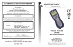
MONARCH INSTRUMENT
Instruction Manual
ACT-1B Series
Panel Tachometer
Printed in the U.S.A.
Copyright 2009 Monarch Instrument, all rights reserved
1071-4843-111R
0909
15 Columbia Drive
Amherst, NH 03031 USA
Phone: (603) 883-3390
Fax: (603) 886-3300
E-mail: [email protected]
Website: www.monarchinstrument.com
DECLARATION OF CONFORMITY
Safeguards and Precautions
1.
2.
Read and follow all instructions in this manual carefully, and
retain this manual for future reference.
Do not use this instrument in any manner inconsistent with
these operating instructions or under any conditions that
exceed the environmental specifications stated.
3.
Be sure the power supplied to this instrument matches the
specification indicated on the rear panel of the instrument.
4.
Be sure all power is removed before making or removing any
connections to or from this instrument.
5.
This instrument is not user serviceable. For technical
assistance, contact the sales organization from which you
purchased the product or Monarch Instrument directly.
In order to comply with EU Directive 2002/96/EC on Waste
Electrical and Electronic Equipment (WEEE): This product
may contain material which could be hazardous to human health
and the environment. DO NOT DISPOSE of this product as unsorted municipal waste. This product needs to be RECYCLED in
accordance with local regulations, contact your local authorities
for more information. This product may be returnable to your distributor for
recycling - contact the distributor for details.
Monarch Instrument’s Limited Warranty
www.monarchinstrument.com for details.
applies.
As Manufacturer:
Monarch Instrument
Division of Monarch International Inc.
15 Columbia Drive, Amherst NH 03031 USA
declares under Monarch’s sole responsibility that the product:
Name:
ACT - Panel Tachometer
Models: ACT-1B
to which this declaration relates is in conformity with the following standards:
EMC:
EN50082-1:1997
EN50082-2:1995
EN55011:1991 Group 1 Class B
and therefore conforms with the requirements of Council Directive 89/336/EEC
relating to electromagnetic compatibility. (File R-351 4N2).
See
Warranty Registration and Extended Warranty coverage available
online at www.monarchinstrument.com.
8th October 1999
Manufacturer (Amherst,NH)
Alan Woolfson, VP Engineering (Authorized Signature)
@CH_A/LOEND = 12 (or 1_SEC, HALF) Sets low end time. This allows a
min reading of 5 RPM, 60 RPM, or 120
RPM.
@CH_A/GATE
Shows Gate Speed. (Default is 12)
@CH_A/GATE = STD (1/100 Second) or FAST (1/1000 second). Sets
Gate Speed (Default is 1/100)
@DECPT
@DECPT = NONE, 1, 2, or 3
@DAC1/ FSCAL
@DAC1/FSCAL = xxx.xx
@DAC1/0SCAL
@DAC1/0SCAL = xxx.xx
@OUTPT
@OUTPT = POS or NEG
11
OVERVIEW ..................................................................................... 1
INSTALLATION and POWER .......................................................... 1
Shows the number of decimal places
displayed
Sets the maximum number of decimal
places
Installation ............................................................................... 2
Shows Analog Out Full Scale
Sets the Reading value that the Analog
output will output Full Scale (5V or
20mA). Depends on TYPE.
Shows Analog Out Zero Scale
Sets the Reading value that the Analog
output will output Zero Scale (0V or
4mA). Depends on TYPE. (Default is
0.00)
SENSOR CONNECTIONS ............................................................. 3
Shows pulse output polarity
Sets pulse output polarity
OPTIONS ........................................................................................ 8
@DISPR
Shows Display Update Rate
@DISPR = HALF or 1_SEC or 1.5_S. This sets the maximum display
update rate to one half a second, 1 second
or 1 ½ seconds between updates.
@SERNO
TABLE OF CONTENTS
Shows unit Serial Number
Power ...................................................................................... 2
USB Programming Cable and Software ................................ 3
OUTPUT OPTIONS ......................................................................... 4
Current Output Option (IO) ...................................................... 5
Analog Output Option (AO) ...................................................... 6
Pulse Repeater Option (PO) ................................................... 6
SPECIFICATIONS ........................................................................... 7
ACCESSORIES / SENSORS .......................................................... 9
APPENDIX A - Serial Programming Commands ......................... 10
OVERVIEW
Appendix A - Serial Programming Commands
The ACT-1B is an economical and easy to use digital tachometer that displays
rotational speed directly in RPM or RPS on a 5-digit red 0.56” high LED display
using a speed sensor providing a single (or multiple) pulse(s) per revolution. The
number of pulses per rev is factory set at time of ordering and can be user programmed
from 1 to 999 using the optional USB Programming Cable and PM Remote Software.
Power may be either universal 100 to 240 Vac (50/60Hz), or optionally, 12 Vdc or 24
Vdc isolated. The ACT-1B accepts input signals from optical, proximity, magnetic,
infrared or laser sensors, or direct TTL or external ac inputs. The ACT-1B is suitable
for panel mounting or bench top use with convenient screw terminal connections on
the rear panel of the instrument.
If specified at time of order placement, the ACT-1B may be equipped with
either an optional 4 to 20 mA current output (IO) or 0 to 5 Vdc analog output
(AO) proportional to speed, and/or a TTL pulse repeater output (PO).
INSTALLATION and POWER
The ACT-1B enclosure is a standard 1/8 DIN size requiring a 3.58” wide by
1.74” high (91x44 mm) mounting hole.
ACT Front View
ACT Side View
Figure 1 Dimensions in Inches (mm)
1
Programming the unit requires the optional USB Programming Cable with
associated PM Remote software and a PC running Windows XP or later
with an available USB port.
All serial commands are @ then two or more characters or words separated
by a delimiter “/”. One or two numbers follow some commands. All valid
commands respond immediately with an “OK” or data, or “ERR” if incorrect.
Default baud rate is 9600.
Communication requires the USB Programming Cable.
@PI
@C2
@D0
@D1
@D2
@MX
@MN
@RE 32
@RE 64
@RE 96
Product Information, Shows Product name \n Firmware revision \n
Shows all settings
Sends current display value once
Sends display data continuously (at up to display update rate)
Stops sending data
Sends Max reading
Sends Min reading
Resets Max
Resets Min
Resets Max and Min
@CH_A/TYPE
@CH_A/TYPE = RPM
@CH_A/TYPE = FREQ
@CH_A/TYPE = SCALE
@CH_A/TYPE/SCALE = 30.00
Shows current type
Sets scale to 60 so displays in RPM.
Sets scale to 1 so displays in hertz.
Scale mode. Enter Scale factor.
This will set the SCALE factor to 30.00
@CH_A/INPUT
Shows sense of the trigger input
@CH_A/INPUT = POS (or NEG) Sets the sense of the input trigger
@CH_A/LOEND
Sets how long (in secs) with no pulses
before the tachometer shows 0.
10
ACCESSORIES / SENSORS
Installation
T-5
Remove the mounting clips, if fitted, and install the unit into the panel from
the front. From the rear of the unit, install the mounting clips on each side
and tighten the mounting screws against the rear of the panel.
Reflective Tape - 5 foot (1.5 m) roll, 0.5 inch (10 mm) wide
USB Programming Cable with PM Remote Software on CD:
Enables the user to program the ACT-1B using a PC with
USB connection. The software also allows remote monitoring
of the RPM using a graphic display or an ExcelTM spreadsheet.
ROLS-W
Remote Optical Laser Sensor with 8 foot cable
ROS-W
Remote Optical Sensor with 8 foot cable
ROS-P-25
Remote Optical Sensor with 25 foot cable (must cut plug off)
ROS-HT-W-25
WARNING:
Do not over tighten the mounting screws.
Power
Power to the unit is connected to the terminals under the section labeled
POWER on the rear panel. Be sure the power supplied matches the
specification indicated on the rear panel. Refer to Figure 2 below.
Remote Optical Sensor for high temperature applications
to 257 °F (125 °C) with 25 foot cable
P5-11
Proximity Sensor
M-190W
Magnetic Sensor with 8 foot cable
MT-190W
Magnetic Trigger Sensor with Amplifier Module, 8 foot cable
GE-200
Gasoline Engine Electromagnetic Inductive Sensor and
amplifier with 23 feet of cable
IRS-W
Infrared Sensor with 8 foot cable
USB
Programming
Jack
Figure 2 ACT-1B Rear Panel
If the unit is ac powered (100 - 240 Vac), connect the Live (Hot) wire to
the terminal marked L+ and the Neutral (Return) wire to the terminal
marked N-.
If the unit is dc powered, connect the dc supply Positive to the terminal
marked L+ and the dc supply Negative or Common to the terminal
marked N-.
9
2
USB Programming Cable and Software
The 3.5 mm connection “hole” in the center bottom of the rear panel is for the
optional USB Programming Cable (p/n 6180-031), which comes with Windows ™
compatible PM (Panel Meter) Remote Software on CD. The cable and software
combination allows the user to configure: operation mode, analog output scaling,
decimal places, display update rate and pulses per input. The user can also view real
time data in digital format and/or through Microsoft® Excel. Software instructions are
included on the software CD.
This product is designed to be safe for indoor use under the following conditions
(per IEC61010-1):
Installation Category II
per IEC 664
Pollution Degree Level II
per IEC 664
Operating Temperature
32-122 °F [0-50 °C]
Humidity
Maximum relative humidity 80% for temperature up to 88 °F
[31 °C] decreasing linearly to 50% relative humidity at
104 °F [40 °C]
SENSOR CONNECTIONS
OPTIONS
A speed sensor (not included) is connected to the terminals under the section
labeled INPUT on the rear panel. Refer to Figures 2 and 3.
IO:
4 to 20 mA current output
AO:
0 to 5 Vdc analog output
Connections and their functions are as follows:
+VA
Positive +12 Vdc to provide power to optical, laser, infrared
or amplified magnetic sensors. Maximum load is 75 mA dc.
Optionally 5 or 24 Vdc supply may be ordered.
PX+
Positive +12 Vdc supply for use with two-wire proximity
sensors. Maximum load for proper operation with two-wire
sensors is 25 mA.
SIG
Positive input signal from the speed sensor. Accepts TTL
pulses or ac signals, unipolar and bipolar, from 1.5 Vac to 50
Vac. (Contact the factory for increased sensitivity.) Connect
the signal wire from three-wire sensors or the positive side of
two-wire magnetic sensors to this terminal. Typical input
impedance is 10 Kohms.
NOTE: Full scale RPM must be specified for the above
options when ordering unless the USB
Programming Cable and PM Remote Software is
ordered as a separate item.
PO:
0 to 5 V TTL compatible pulse output
NOTE: Pulses out per revolution equal pulses in per
revolution.
CAL-N.I.S.T.
N.I.S.T. Traceable Certificate of Calibration
COM Common or Negative connection for both signal and power
from most sensors.
Refer to Figure 3 for connection of Monarch standard sensors. The
connections are typical for these types of sensors.
3
8
SPECIFICATIONS
Range:
Accuracy:
Resolution:
Display:
Display Update:
PX+
INPUT
SIG
COM
+VA
PX+
INPUT
SIG
COM
+VA
PX+
INPUT
SIG
COM
+VA
PX+
INPUT
SIG
COM
5 to 99,999 RPM
±1 RPM or 0.005% of reading
1 RPM (user programmable to 0.0001*)
5 digit, 0.56” (14 mm) high red LED
Twice per second above 120 RPM (user programmable
to 0.5, 1, or 1.5 second*)
Dimensions:
1/8 DIN by 4.5” (114 mm) deep
Power Supply:
Standard: 100 - 240 Vac ±10%, 50/60 Hz, 5VA
Optional: 12 or 24 Vdc ±10%, Isolated, 5 Watts
Inputs:
Universal input for optical, proximity, two-wire or threewire magnetic, infrared or laser sensors
TTL input or 2 Vac to 50 Vac peak to peak input
Standard input is 1 pulse per revolution. (user
programmable from 1 to 999*)
Sensor Excitation: 12 Vdc at 20 mA for proximity sensors, 12 Vdc at 75 mA
for all other sensors, Optional 5 or 24 Vdc available
Recommended Sensors: Optical
- Monarch ROS-W
Proximity - Monarch P5-11
Magnetic - Monarch M-190W or MT-190W
Infrared - Monarch IRS-W
Laser
- Monarch ROLS-W
IO Option: 4 to 20 mA out, 16 bit resolution 12Vdc compliance voltage. See
page 7 for maximum load calculation. Full scale RPM settings as
specified when ordered. (user programmable*)
AO Option: 0 to 5 Vdc out, 5 mA 16 bit resolution. Full scale RPM settings
as specified when ordered. (user programmable*)
PO Option: 0 to 5 V TTL pulse, non-inverting, one pulse out for each
pulse in. (Positive or negative out programmable*)
* Requires optional USB Programming Cable and PM Remote Software
7
+VA
BLACK
WHITE
BROWN
Shield to
COM
M-190W
MAGNETIC
SENSOR
BLUE
BROWN
BLACK
Link SIG to
COM
P5-11
PROXIMITY
SENSOR
BLUE
Shield to
COM
ROS-W - OPTICAL SENSOR (SHOWN)
R0LS-W - REMOTE LASER SENSOR
IRS-W - INFRARED SENSOR
MT-190W - AMPLIFIED MAGNETIC SENSOR
AC or TTL
SOURCE
Figure 3 Sensor Connections
OUTPUT OPTIONS
The ACT-1B may be equipped with either a Current Output (IO) or an
Analog Output (AO), and/or a TTL Pulse Output (PO).
NOTE:
Full scale RPM settings must have been specified when ordered
or may be user programmed using the optional USB Programming
Cable and PM Remote Software.
The Current or Analog Outputs are connected to the terminals in the section
labeled ANALOG OUTPUT OPTION on the rear panel. The actual output
is marked. The Pulse Output is connected to the terminals under the
section labeled OUT on the rear panel.
CAUTION:
The IO or AO COM may NOT be isolated from the other
COM connections.
4
Current Output Option (IO)
Analog Output Option (AO)
The current output is 4 to 20 mA. This output is a current source and
has a 12 Vdc internal compliance voltage. (Optional 24 Vdc may be
ordered).
The analog output is 0 to 5 Vdc.
Typical connections are as follows: (See Figure 4.)
Connect the Positive side of the signal to the terminal marked OUT,
and the Return side of the signal to the terminal marked COM.
NOTE:
Connect the Positive side of the load to the terminal marked OUT
and the other (Negative) side of the load to the terminal marked
COM.
Do not use an external voltage supply.
If your ACT-1B is equipped with either a current output or
an analog output, the full-scale output has been factory preset
to the speed range specified at the time of purchase. The
output range may be programmed using the optional USB
Programming Cable and PM Remote Software.
Pulse Repeater Output Option (PO)
The Pulse Repeater output provides a conditioned TTL positive going
5 V pulse out for each pulse in.
Connect the Positive signal wire (+5 V pulse) to terminal marked +P
and the Return to the terminal marked COM in the rear panel section
labeled OUT.
NOTE:
The polarity of the optional pulse output can be set by the
user using the optional USB Programming Cable and PM
Remote Software.
Figure 4 Current Output Option Connections
NOTE:
With the internal 12 Vdc compliance voltage the maximum
load for the current loop is 500 Ohms.
If the optional 24 Vdc compliance option is ordered the
maximum load will be 1000 Ohms.
5
6