1
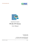
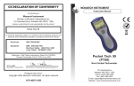
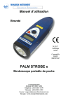
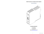
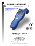
CE DECLARATION OF CONFORMITY
MONARCH INSTRUMENT
Instruction Manual
As Manufacturer:
Monarch Instrument
Division of Monarch International Inc.
15 Columbia Drive, Amherst NH 03031 USA
declares under Monarch’s sole responsibility that the product:
Name:
Remote Optical Self-Powered Sensor
Models: SPSR-115/230
SPSR-115/230
to which this declaration relates is in conformity with the following standards:
EN61326:1997 EMC /A1:1998/A2:2001/A3:2003
Specifically: EN55022 Class B
EN61000-4-2
EN61000-4-3 EN61000-4-4 EN61000-4-6
and therefore conforms with the requirements of Council Directive 89/336/EEC
relating to electromagnetic compatibility when installed in accordance with the user
guide. The testing of this product was performed by Retlif Testing Laboratories, NH,
in February of 2007 (File R-4702N-8).
14th February 2007
Manufacturer (Amherst,NH)
Alan Woolfson, VP Engineering (Authorized Signature)
Printed in the U.S.A.
Copyright 2008, Monarch Instrument, all rights reserved
1071-4847-113R
0808
SPSR-115/230
Self-Powered Sensor
TTL Pulse Output
15 Columbia Drive
Amherst, NH 03031 USA
Phone: (603) 883-3390
Fax: (603) 886-3300
E-mail: [email protected]
Website: www.monarchinstrument.com
SENSOR / OPTIONS AND ACCESSORIES
Safeguards and Precautions
1.
2.
3.
Read and follow all instructions in this manual
carefully, and retain this manual for
future reference.
Do not use this instrument in any manner
inconsistent with these operating instructions or
under any conditions that exceed the environmental
specifications stated.
This instrument is not user serviceable. For
technical assistance, contact the sales
organization from which you purchased the product
or Monarch Instrument directly.
In order to comply with EU Directive 2002/96/EC on Waste
Electrical and Electronic Equipment (WEEE): This product
may contain material which could be hazardous to human
health and the environment. DO NOT DISPOSE of this
product as unsorted municipal waste. This product needs
to be RECYCLED in accordance with local regulations, contact your
local authorities for more information. This product may be returnable
to your distributor for recycling - contact the distributor for details.
NOTE: This product contains Nickel Metal Hydride (NiMH) batteries
which must be recycled. Refer to the Battery Disposal section on
page 7 for details.
ROS-P
Remote Optical Sensor with 8 foot [2.5 m] cable and mounting
bracket
ROS-P-25
Remote Optical Sensor with 25 foot [7.6 m] cable and
mounting bracket
IRS-P
Infrared Sensor with 8 foot [2.5 m] cable for use without
reflective target at 0.5 inch [12.7 mm] gap (5 to 500,000
RPM)
MT-190P
Magnetic Trigger Sensor/Amplifier with 8 foot [2.5 m] cable
- 0.250” [6.4 mm] operating gap from target, 2” (L) x 5/8”
[50.8 x 15.9 mm]
EC-25P
25 foot [7.6 m] Extension Cable for remote sensors with male
1/8” [3.5 mm] phone plug to female 1/8” [3.5 mm] connector
T-5
Reflective Tape, 5 foot [1.5 m] roll, ½ inch [13 mm] wide
T-5WP
Waterproof Reflective Tape (honeycomb pattern), 5 foot [1.5
m] roll, 1 inch [25 mm] wide
BP-R
Replacement NiMH Battery Pack (for SPSR-IM ONLY)
PSC-2U
Universal Recharger with plugs, 115/230 Vac - 50/60 Hz
See
CA-DCSPSR 6 foot [1.8 m] DC Adapter Cable assembly with cigarette
lighter plug to operate and charge SPSR-IM from 12 Vdc
Warranty Registration and Extended Warranty coverage
available online at www.monarchinstrument.com.
8
Monarch Instrument’s Limited Warranty applies.
www.monarchinstrument.com for details.
The pulse signal on the connector marked “Output” provides a sharp
leading edge for reliable and repeatable triggering of the connected device.
This output is capable of driving a hundred feet of coax cable. Be sure
to select the direction (0 to 5 Vdc or 5 to 0 Vdc) of this signal to provide
the required polarity of the leading edge to properly trigger the connected
equipment.
Operational Check
Correct operation of any SPSR Self Powered Sensor can be checked at any
time by aiming the sensor at an original design fluorescent light and observing
7200 ±2 counts on the instrument connected to the BNC output.
NOTE:
In countries with a 50 Hz. Power line frequency, the instrument
connected to the BNC output will read 6000 ±2.
BATTERY DISPOSAL
Prior to disposing of the SPSR-IM, the user must remove the Nickel Metal
Hydride batteries. To do this, remove the four (4) rubber feet on the bottom
of the unit. This will expose four (4) screws that must be removed to
dismantle the bottom case piece, exposing the batteries. Remove the batteries
and place tape over the battery terminals to prevent them from shorting. The
batteries should be sent to a recycling center or returned to the factory. The
rest of the parts may now be disposed of.
NOTE:
7
This product contains Nickel Metal Hydride (NiMH) batteries.
Replace only with the same type of battery – Rechargeable NiMH.
TABLE OF CONTENTS
INTRODUCTION ................................................................... 1
COMPONENT SPECIFICATIONS ......................................... 1
SPSR-IM Interface Module .............................................. 1
ROS-P Remote Optical Sensor ...................................... 3
FUNCTIONS AND OPERATION ............................................ 4
SPSR Interface Module ................................................... 4
Connections ............................................................. 4
Controls ................................................................... 4
LED Indication .......................................................... 5
Recharging the Batteries .......................................... 5
SPSR-115/230 Series - SPSR-IM with ROS-P ................ 6
ROS-P ..................................................................... 6
Operating the SPSR as a triggering source .............. 6
Operational Check .......................................................... 7
BATTERY DISPOSAL ........................................................... 7
SENSORS / OPTIONS AND ACCESSORIES ....................... 8
INTRODUCTION
SPSR-115/230 Series - SPSR-IM with ROS-P
The SPSR-IM Self Powered Sensor Interface Module is a self-contained,
rechargeable battery powered device for developing a TTL compatible one
pulse per revolution output for triggering external equipment such as vibration
analyzers, spectrum analyzers, stroboscopes, data acquisition equipment,
tachometers, balancers, waveform analyzers and magnetic tape recorders.
The SPSR-115/230 consists of the SPSR-IM Interface Module described
above, an ROS-P Remote Optical Sensor with eight foot cable and mounting
bracket, and a PSC-1U (115/230 Vac) external power connection. One foot
of T-5 Reflective Tape is also supplied.
The SPSR-115/230 is
comprised of the SPSR-IM
Interface Module, which
provides power to a sensor
and couples the sensor to a
BNC output; an input
sensor with a visible red
LED light source (ROS-P);
and a battery recharger.
SPSR-115/230
(SPSR-IM, ROS-P and Universal Recharger)
An optional infrared light source
(IRS-P) or an amplified magnetic
sensor (MT-190P) may also be
combined with the SPSR-IM
Interface
Module
when
appropriate.
(See
separate
instructions for these configurations.)
IRS-P
Infrared Sensor
MT-190P
Magnetic Trigger Sensor
COMPONENT SPECIFICATIONS
SPSR-IM Interface Module
Internal Batteries: Nickel Metal Hydride (NiMH) Battery Pack, 4.8 Vdc
Operating Interval: >40 hours typical with ROS-P (~40mA load)
Charge Time:
up to 4 hours
1
ROS-P
When connected to the SPSR-IM as described above, the ROS-P
illuminates the target with a visible red light from a high intensity LED
and detects the reflected pulses from the rotating reflective tape target
with an internal photo-detector. The ROS-P Remote Optical Sensor is
capable of detecting a reflected pulse from T-5 Reflective Tape targets at
distances of up to 3 feet and angles up to 45 degrees from the target. The
sensor is supplied with a set of two M16 jam nuts and a 90° angle
slotted aluminum mounting bracket.
For most applications, a 1/2" square piece of T-5 Reflective Tape should
be applied to a clean area on the rotating object. The sensor should be
mounted and optically aligned to illuminate the reflective target once per
revolution. It is recommended that the optical sensor be placed at a
slight angle (approximately 10-15 degrees) from perpendicular, so
that the sensor will detect only the reflected pulses from the target.
The sensor should be at least 2 inches and no more than 3 feet from the
target. The green LED On-Target Indicator on the ROS-P will blink at the
input frequency or be continuously illuminated when properly aimed.
Operating the SPSR as a triggering source
Once the ROS-P input sensor is properly mounted and aligned, further
connections and operation should proceed in accordance with the
functions and descriptions under the SPSR Interface Module sections
entitled ‘Connections’ and ‘Controls’.
6
will operate directly from external power any time that it is being supplied.
Otherwise, it functions on internal battery power.
The “Output Selection” switch determines the polarity of the leading
edge of the TTL compatible output signal. In the NON-INVERTING
position, the output signal on the BNC connector will be a negative
going 5 to 0 Vdc pulse derived directly from the conditioned sensor
output. When the INVERTING position is switch selected, the BNC
output signal will be a positive going 0 to 5 Vdc, TTL compatible.
LED Indication
Unit operational = solid green
Unit charging
= blinking red
Charging done
= solid red
NOTE: Short red blinks followed by long blink = Charge error,
contact factory
Recharging the Batteries
To recharge the SPSR-IM Interface Module batteries:
1. Connect the recharger/power supply or external power cable
to the “External DC” input connector.
2. Connect the recharger/power supply into a working ac outlet,
or the external power cable to a regulated power source of 5 to
12 Vdc.
3. Be sure the “Power” switch is in the OFF (CHARGE) position.
The red “CHARGE” LED will indicate that the batteries are
being charged. Allow up to 4 hours to fully charge.
Output: TTL compatible pulse, INVERTED or NON-INVERTED – switch
selectable. With an ROS (negative pulse) input, the output will be
a positive pulse when set to inverted or negative pulse when set to
non-inverted. Optionally, the output can be open collector (external pull up is required).
Bandwidth:
0 to 100 kHz
Battery Current Draw: 12mA with 10 kΩ load (operational)
9V Input Current Draw: 14mA with 10 kΩ load (operational)
Power Supply: PSC-1U or PSC-2U (operational/charge):
Conforms to UL STD 60950-1
Certified to CSA STD C22.2 No. 60950-1-03
OR 9Vdc to 15Vdc with CA-DCSPSR Cable
LED Indicator:
Status indication, see LED Indication section
Output Connector: BNC Connector (female)
Operating Temp: 32° F to 122° F [0° C to 50° C]
Weight:
8.3 oz. [235 grams]
Dimensions:
5.0" x 2.5" x 1" [127 mm x 64 mm x 25 mm]
5.00[127]
1.00[25]
NON-INVERTING
INVERTING
OUTPUT SELECTION
2.50[64]
OUTPUT
CHARGE
Remote
Sensor
Input Jack
EXTERNAL
DC
POWER
OFF ON
Recharger
Jack
1.00[25]
SPSR-IM Dimensions
5
2
ROS-P Remote Optical Sensor
FUNCTIONS AND OPERATION
Operating Envelope:
Speed Range:
Illumination Source:
Operating Temp:
Output Signal:
On-Target Indicator:
Material:
Lens:
Cable Length:
Dimensions:
SPSR Interface Module
Up to 3 feet [0.9 m] and 45° from reflective target
1 to 250,000 RPM
Visible red LED, 5 Vdc @ 30 mA
14° F to 158° F [-10° C to 70° C]
5 to 0 Vdc TTL compatible pulse
Green LED on end cap
303 Stainless steel
Acrylic plastic
8 feet [2.5 m] Standard
Threaded Tube - 2.90” L x 0.625 “ diameter [M16
x 1.5 x 74 mm] supplied with two M16 jam nuts
and mounting bracket
The SPSR Interface Module (SPSR-IM) provides power to the input
sensor, receives and optionally inverts the return pulse signal, and provides
a switch selectable positive going 0 to 5 Vdc or negative going 5 to 0 Vdc
pulse train trigger output on a BNC connector. Connections and operation
are common to all SPSR models. Fully charged internal NiMH batteries will
typically provide greater than 40 hours of continuous operation. In addition,
the SPSR system can be operated continuously on external power by use of
the recharger/power supply or cable provided.
Connections
Connect the input sensor via the 1/8” [3.5 mm] phone plug to the mating
connector on the SPSR-IM. This sensor may remain connected even
when recharging the internal batteries of the SPSR-IM.
Connect the output signal cable to the BNC connector on the opposite
end of the SPSR-IM and to the external equipment to be triggered.
If operating from the recharger/power supply, connect the recharger to
the connector marked “External DC” on the SPSR-IM and connect the
wall unit to the appropriate power source. When using the CADCSPSR cable, connect the cable to the connector marked “External
DC” on the SPSR-IM and connect the cigarette lighter connector to the
appropriate power source.
Controls
The “Power” switch on the SPSR-IM controls both the operation and
the charging of the system. The unit will only charge from external
power in the power OFF position. In the power ON position, the unit
ROS-P and mounting bracket Dimensions
3
4