1
<
cross sect.
area
(mm 2)
Resistivity
Ohm/km
5A
10A
20A
50A
150A
2.5
8.21
12.2
6.1
3.0
1.2
0.4
Maximum length in meters to limit voltage drop to 0.5V or less
4
5.09
19.6
9.8
4.9
2.0
0.7
6
3.39
29.5
14.7
7.4
2.9
1.0
10
1.95
51.3
25.6
12.8
5.1
1.7
16
1.24
80.6
40.3
20.2
8.1
2.7
25
0.795
125.8
62.9
31.4
12.6
4.2
35
0.565
177.0
88.5
44.2
17.7
5.9
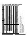
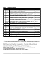
Table 3-2: Maximum wire length for 0.5V drop on lead (in meters)
For current not shown in tables 3-1 and 3-2 use formula: Maximum length=500/(current*resistivity)
Where current is expressed in ampers and resistivity in ohms/km or ohms/1000ft.
3.7.2 Wire termination
The wires should be properly terminated with terminals securely attached. DO NOT use non
terminated wires for load connection at the power supply.
CAUTION
At local sensing, short between +LS or +S to -V or -S or -LS will cause damage to the
power supply. Reversing the sense wires might cause damage to the power supply
at local and remote sensing.
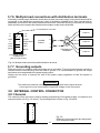
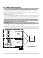
3.7.3 Single load connection, Local Sensing
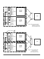
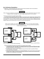
Fig. 3-1 illustrates the connection of a single load to the power supply using local sensing. This
connection is made via the “External Control Connector” located on the rear panel of the power supply.
Local sensing is suitable for applications where load regulation is not critical.
14
13
-S
- LS
+S
+LS
-S
On/Off
+LS
COM
P
+V
+
VRFI
-V
_
RCVP
- LS
Output Good
VCVP
VRFV
VCCP
RCCP
2
POWER
SUPPLY
1
LOAD
-S
EXTERNAL CONTROL
CONNECTOR
(ZUP rear panel view)
Fig. 3-1: Single load connection, Local Sensing
14