1
4.4.14 Series Operation
1. GENERAL: Two power supplies of the same rating can be connected in series to increase the
output voltage or to provide bipolar output voltage.
CAUTION
When two power supplies are connected in series, they should be programmed to the same output
voltage to prevent damage to the lower voltage supply at short circuit condition.
2. Series connection for increased output voltage:
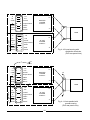
2.1 General: At this operation mode, two units are connected so their outputs are summed. Set the
current limits of each power supply to the maximum that the load can handle without damage. It is
recommended to connect diodes in parallel to each unit output to prevent reverse voltage during startup condition or in case one of the units shuts down. Each diode should be rated to at least the power
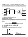
supply’s output current. Refer to Fig: 4-12 and 4-13 for this operating mode.
CAUTION
When power supplies are connected in series, and the load or one of the output terminals
is grounded, no point may be at a greater potential ( + or - ) from ground than that specified
on the front panel marking.
+LS
POWER
SUPPLY
- LS
+LS
+S
+
POWER
SUPPLY
_
-S
+
- LS
+S
+
_
-S
+
LOAD
LOAD
+LS
POWER
SUPPLY
- LS
+S
_
+LS
+
POWER
SUPPLY
_
-S
- LS
+S
_
+
_
-S
Fig. 4-13: Series connection, remote sensing.
Fig. 4-12: Series connection with local sensing.
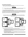
2.2 Remote programming at series operation for increased output voltage:
1. Programming by external voltage; The analog programming circuits of the ZUP power supply
are referenced to the - Sense potential. Therefore, the circuits used to control each unit must
be separated and floated from each other.
2. Programming by external resistor: Programming by external resistor is possible. Refer to
Fig. 4-5 and Fig. 4-6 for details.
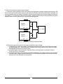
3. Programming via the communication port (RS232/RS485): The communication port is isolated
from the output voltage, therefore power supplies connected in series, can be chained using
the Remote-in and Remote-out connectors.
35