1
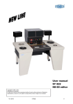
USER MANUAL ST 2520
Copyright © 2008 – 2013.
Steenbeck is a trademark.
No part of this manual may be reproduced without the prior written permission of Steenbeck.
Specifications, colours etc. are subject to change without notice. Images are an example.
section
0.0
1.0
2.0
3.0
4.0
5.1
5.2
6.0
7.0
contents
assembly instructions
introduction
general features
technical data
important safety information
important warranty information
operation instructions ST2520
6.1 preface
6.2 winding units
operation overview
1
2-3
4
4
5
6
6
7
fig. 1 - 6b
9 - 10
operation
8.1 universal counter (optional)
maintenance instructions (mechanics)
9.1 preface
9.2 tools
9.3 adjusting frictions
9.4 servicing / replacements frictions
9.5 further maintenance instructions
9.6 toolkit
11
12
13
13
13
14
14 - 15
15
15
7 – 22 for mechanical maintenance instructions
16 - 21
8.0
9.0
fig.
page
V03-2013
ST2520
8
1
STEENBECK ST2520 Film Rewinder / Inspection Table
1.0 INSTRUCTIONS. (assembly)
Please read this instruction carefully.
NEVER lift the film rewinder at the top plate.
1. Fasten rollers to film rewinder legs (if removed for shipping)
Stop rollers go to the front.
2. Install the counter display (when delivered and removed for shipping)
3. Insert flat cable connector of the counter display (when delivered) to
adjacent plug. (be careful not to bend any contacts).
Install working lamp (when delivered) and plug it in the wall socket at
the back of the table.
4. When counter is fitted, fit the sprocket to the counter pick up shaft
(when removed for shipping). Make sure that sprocket is in the
lowest position (turn sprocket while holding lower ring in position).
Check if pinch roller arm closes properly.
5. Exchangeable rollers can be put on the special platform under the
counter display. (fig. 11)
6. Connect foot pedal control cable to adjacent plug at the bottom of
film rewinder housing, left side. (when delivered)
7. Check line voltage and frequency correspond to the readings in the
machine type and serial number label at the rear of the frame/housing.
8. Check if power plug fits into the local socket.
if not, replace plug for a local plug:
yellow/green: earth
blue:
neutral
brown:
live / phase
9. Please check the power ground system of the wall socket is OK.
This is important for the safety of the operator and static electricity.
10. Switch on power and run table slowly in left and right direction.
11. Check counter system (if delivered) by turning by hand the sprocket.
12. Check lighting with dimmer and ground glass.
13. Connect foot control (if delivered).
14. Check foot control.
15. Put a little vaseline on inner plastic friction rings of the film plates
(see fig. 20, page 21) and ring on friction base plate (fig. 15, page 19)
16. Put film plates on the friction discs.
V03-2013
ST2520
2
17. Leave the table running slowly and read carefully the users manual including
technical sheets before starting to work with the ST2520.
When running the table slowly, you might hear a buzzer and the table will
stop. Set potention meter back in “0” position.
Align potentiometer so the table will run constant slow, just before the
the point the buzzer will be activated.
18. Read the manual.
V03-2013
ST2520
3
2.0 INTRODUCTION STEENBECK ST2520:
Congratulations purchasing the flatbed 2 plate ST2520 motor film rewinder / film
inspection table. This machine is a fine piece of film equipment and the ideal partner
for film archives, film laboratories, projection rooms or film restoration companies.
The ST2520 offers:
- easy and safe motorized film handling by hand or optional foot control
(option 2259).
- very slow speed ideal for inspection film perforation, damages, cutting/ editing
and cleaning film purposes.
- fast winding of 16 and 35mm picture / sound film and 17,5mm sound film in Awind .
- checking measurements of film by optional electronic universal counter.
(option ST2258)
3.0 GENERAL FEATURES:
- Single motor drive system for fully variable speed.
- Small and easily moveable chassis.
- Solvent resistant table top with enough space to work for operator.
- Maximum speed of 6 meters / 20 feet per second in both directions.
- Adjustable wind tensions.
- Maximum capacity of approx. 650 meter / 2000 feet of acetate film on bobbins or
16mm film reels or 1000 meter / 3000 feet of PE sound film.
- Easy and safe motor operation by hand or optional foot control.
- Ultra low speed film transport of approx. 0,5 frames per second (35mm) ideal for
film inspection
like damages, joins and cleaning film by hand.
- Automatic stop at film end or when film breaks with warning signal by buzzer.
- Accurate counting using optional electronic universal processor counter with
sprockets 16mm and 35mm or with optional special roller (toothless) for
shrunken and damaged material, accuracy less than 0,5%.
- Large ground glass back-illuminated by a 7000K (approx.) light source.
- Dimmer with socket is installed for the optional work lamp (max. 75 watt)
- Standard installed with a elapsed hour counter for maintenance purposes.
- All guide rollers fitted with ball bearings for extended life.
- Transport (front) castors with brakes.
V03-2013
ST2520
4
4.0
TECHNICAL DATA:
The 2 plate motor film rewinder / film inspection table is capable of handling all
picture and magnetic sound films 16 / 17,5 / 35mm.
Motorized winding and speed regulation is accomplished by hand or foot control.
One-motor drive with belt system for both winding directions.
The minimum and maximum speed range is available in both directions.
Fully variable rewinding speed of max. 6 meters per second ( EU regulation)
This is for 650 meters / 2000 feet of film is approx. 2 minutes.
Adjustable film tension of the frictions remains steady over full film length.
Take-ups with film plates to accept bobbins according to DIN 15531 and 16mm reels
according to DIN 15621.
Power requirements:
On request:
Power consumption:
Table size:
Weight:
220 / 240 Volts – 50 / 60 Hz.
100 / 110 Volts – 50 / 60 Hz.
approx. 600 watt. (in full running mode)
width 107cm. - depth 70cm. - height (bench) 81cm.
height with counter 97cm. / w/o/ counter 91,5cm.
approx. 60 kg.
Fuses:
Main power inlet EU socket (rear of frame):
For 220/240 Volts: 2 x 4 A T - for 100/110 Volts: 2 x 6,3 A T
Illuminated ground glass (outside):
For 220/240 and 100/110 Volts: 1 x 0,5 A T
PSU counter system (inside):
For 220/240 Volts :
1 x 0,315 A T
For 100/110 Volts :
1 x 0,8 A T
Driver board (inside); see fig. 13 page 19
- 1 AT
- 1 AT
- 4 AT
- 1 AT
All fuses are standard Slow blown / T.
Do not use any fast blown fuses !
OPTIONAL EXTRAS:
ST 58
table working lamp
ST 2258
electronic universal processor counter
including sprockets for (S)16 – 17,5 – 35mm.
V03-2013
ST2520
5
ST 2260
ST 2259
V03-2013
counter roller toothless sprocket for ST2558.
foot control
ST2520
6
5.0 IMPORTANT SAFETY / WARRANTY INFORMATION.
5.1 SAFETY.
Installation of the ST2520 should be done by a Steenbeck engineers, Steenbeck
dealer or qualified/ trained technical personal.
Connect the ST2520 to a proper mains source (within +/- 10%) with the supplied
power cord and should be connected to earth / ground properly.
Earth system must be 100% because:
- safety for the operator in cases of electronic problems within or outside
the ST2520.
- safety for the electronics of the ST2520.
- carry off static electricity.
The ST2520 should be placed in a dry and dust free room.
Temperature: advisable: 5°C - 40°C (40°F - 105°F)
Humidity:
advisable: 30% . . . . 70%
Do not put any warm or cold drinks on the table top plate or shelves.
5.2 WARRANTY.
STEENBECK film equipment is manufactured with greatest care and precision.
Before shipping, several tests are made for many hours to ensure our quality
standards.
STEENBECK film equipment is made for a long life with a minimum of maintenance.
The ST2520 is designed for (re)winding and inspection of all kinds of film (motion
picture) and perforated magnetic sound film material made of nitrate, acetate or
polyester. Not for whatever other material.
If, nevertheless, any part or unit should turn out not to function properly within ONE
YEAR of purchase the ST2520, please report to your Steenbeck dealer or the
Steenbeck factory at once.
Defective parts or units will be either repaired or exchanged.
Steenbeck has the right to inspect the defective part or unit before replacing.
Defective parts should be packed well, shipping costs and risk are for the sender.
Costs for return packing and shipment are for Steenbeck, including risk.
Replaced parts change into our property.
We cannot be held liable for any further compensation.
Please note that our warranty does not cover any damages caused by excessive
load, improper use, lack of maintenance or unauthorized intervention.
V03-2013
ST2520
7
6.0 OPERATION INSTRUCTION ST2520.
6.1 PREFACE.
The Steenbeck ST2520 film rewinder / film inspection table is a highly reliable tool for
working on your valuable motion pictures and magnetic sound films.
It is able to handle 16, 17,5 or 35mm stock.
Be sure only trained personal is working with this film rewinder.
Please be aware of danger caused by long hair, loose shawls, neckties or wide
sleeves when caught by revolving machine parts.
The ST2520 may only be operated in rooms under normal conditions of temperature
and humidity without corrosive atmosphere.
Be sure only to use a fully adjustable working chair according to DIN 4551 to avoid
orthopaedic problems.
The manufacturer of the ST2520 cannot be held responsible for any damage caused
by improper use of equipment or material.
6.2 WINDING UNITS.
We recommend only to use 75mm (3”) and 100mm (4”) film cores / bobbins because
the smaller diameter of 50mm may cause problems under extreme conditions.
Film capacity:
650 meter / 2000 feet of 0,15mm picture film stock.
1000 meter / 3000 feet of 0,09mm standard magnetic sound film stock.
The ST2520 has the same friction top and film plates like the Steenbeck controlling /
viewing and editing tables.
These also can take the 16mm film reels with square centre hole.
We advise to put a thin carton sheet under the spool, so you can’t damage the film
plate.
When you only use spools we advise to take off the film plate (clean the metal base
plate with the white synthetic ring) and put the film reel on the square friction centre.
Depending using plastic or metal 16mm film reels, it is advisable to readjust the
frictions because of the weight of the film reel(s).
For 35mm reels there is no adapter available.
V03-2013
ST2520
8
7.0 OPERATION OVERVIEW.
The three switches on the ST2520 front switch board have the following symbols:
I = on
0 = off
1.
2.
3.
4.
5.
6.
7.
8.
9.
10.
11.
12.
13.
14.
15.
16.
17.
18.
19.
20.
22.
23.
24.
Main power switch (fig. 1 page 9)
Power On indicator lamp (fig. 1)
Switch illuminated ground glass, see 13 (fig. 1)
Switch for working lamp with dimmer (fig. 1)
Speed control by hand with centre click (fig. 1)
Knob for dimmer working lamp (fig. 2 page 9)
Alignment of time from 0 (standstill) to maximum
wind speed for foot switch / control (fig. 3 page 9)
Use slotted screwdriver 2,5x0,6mm
Alignment of time from 0 (standstill) to maximum
wind speed for speed control by hand (5) (fig. 3)
Use slotted screwdriver 2,5x0,6mm
Guide rollers, switchable for 16 / 17,5 / 35mm (fig. 9 page 17)
Counter pick up with interchangeable sprocket for 16mm and 35mm
(fig. 7 – 8 page 16)
Pressure arm, interchangeable for 16mm and 35mm (fig. 7 – 8 page 16)
16 / 35mm format counter switch (fig. 7 page 16)
Illuminated ground glass (fig. 11 page 17).
Platform for interchangeable sprockets, guide rollers and
pressure arm (fig. 11)
Counter display (optional) (fig. 11)
Main power inlet (fig. 5 page 10)
Main power fuses (fig. 5)
Fuse for ground glass (fig. 5)
Working lamp socket (fig. 5)
Foot switch / control (reverse / left - fig. 6 b page 10)
Foot switch / control (forward / right - fig. 6 b)
Film ruler for 16mm and 35mm (fig. 11 page 17)
Time elapsed counter (fig. 4 page 10)
Special roller (toothless) for counter (fig.10 page 17) optional
( for damaged / shrunken film)
Front castor with brake (fig. 6)
V03-2013
ST2520
9
(fig.1)
2
1
3
4
5
(fig.2)
6
( fig.3)
7
V03-2013
8
ST2520
10
(fig.4)
(fig.5)
18
19
16
17
23
(fig.6)
(fig.6b)
right direction
left direction
V03-2013
ST2520
11
8.0
OPERATION.
The ST2520 motorized drive system can be controlled by hand speed control
( fig. 1 #5 page 9) or the optional foot control (fig. 6 b page 10).
When both are installed, the hand speed control is always the master.
You always have to put the hand speed control in the zero position (centre click)
before you can use the foot control. This can be done while winding.
Any deviation of the speed control in clockwise direction will cause the film rewinder
to transport the film from left to right and vice versa.
When you select the speed control by hand of foot from left to right (and v.v.)
the film rewinder will always stop / standstill for a few seconds and will start to wind
into the last chosen direction.
The ST2520 is specially developed for use in archives and laboratories.
The variable speed is smooth and therefore taking good care for your material.
In the very low speed the operator can easily check perforations and damages
by hand without interfering the motor control system.
The ST2520 will stop automatically in case the film breaks of when reaching film end.
There is a buzzer warning signal with this automatic stop.
The warning signal can only be switched off when the hand speed control (fig.1 #5)
is in the zero / central position.
You have several wind modes available:
1. direct from film plate to film plate.
2. via guide roller left or right.
3. via both guide rollers. (fig. 11 page 17)
4. via guide roller left and sprocket for counter (fig. 12 page 17)
To get the best wind result we do advise the mode 3 and 4.
V03-2013
ST2520
12
8.1
UNIVERSAL COUNTER. (optional)
10
1
The Steenbeck universal counter is designed to measure film length (all formats) and
calculate the position and time information in common use.
Additionally, the universal counter may offer extra possibilities for more effective work
on your film rewind / film inspection table.
The counter / calculator functions are controlled by keys No. 1 – 10 (right to left)
1.
2.
3.
4.
5.
6.
7.
8.
9.
10.
frames
feet 35mm
feet 16mm
feet 8Smm
m / dm 35mm
m / dm 16mm
m / dm 8Smm
min / sec 25 FPS
min / sec 24 FPS
min / sec 18 FPS
counts and displays number of frames (max. 1.999.999)
displays film length in feet (16 frames = 1 foot)
displays film length in feet (40 frames = 1 foot)
displays film length in feet (72 frames = 1 foot)
displays film length in meters (1 meter = 52,630 frames)
displays film length in meters (1 meter = 131,200 frames)
displays film length in meters (1 meter = 236,200 frames)
displays elapsed time (1 second = 25 frames)
displays elapsed time (1 second = 24 frames)
displays elapsed time (1 second = 18 frames)
The two digits to the right always indicate numbers of frames.
The other digits show the counter value according to the chosen film format.
A red LED on the key indicates the activated display format.
The green LED is not in use with the ST2520.
Together with the keys you will find one switch and two pushbuttons on the counter
front panel.
Pushbutton C = Clear
Pushbutton HOLD
Switch DIST CTR
Counter is reset to ZERO.
Display is stopped at actual reading.
The counter keeps on counting. When releasing
Pushbutton , counter value is transferred to display.
Setting 1: distance counter on
Setting 0: distance counter off.
The distance counter is activated to measure partical
V03-2013
ST2520
13
length or time values.
It can be reset to ZERO (C)
without effecting the main counter.
9.0
MAINTENANCE INSTRUCTIONS.
9.1 PREFACE.
The Steenbeck ST2520 film rewinder / film inspection table is manufactured and
tested with the greatest care possible. That is why it only requires a minimum of
maintenance to stay in good working order.
This doesn’t mean that the ST2520 doesn’t need maintenance at all.
It needs from time to time some maintenance and we would like to draw your
attention to some details you will find to be of importance.
The main part that needs attention are the two frictions.
These are special frictions with switchable clutches.
When winding forward / to the right, the left friction is a real friction with an adjustable
tension. The clutch of the right frictions is engaged (you hear a click) and becomes a
1 : 1 axle with maximum motor torque.
When you wind reverse / to the left, the system works visa versa.
For adjusting the frictions, see section 9.3.
One of the reason we installed a time elapsed counter (see fig. 4) is to read the hours
the ST2520 was in use.
We strongly advise to dismantle the friction core, clean the friction ring / core and
apply special grease on the friction ring every 150 hours.
For this maintenance, see section 9.4.
CAUTION:
Always make sure to disconnect the mains cable before opening the ST2520
housing. Take the film of the film plates.
In case of running test, just take a small diameter roll of 16mm film when possible.
(approx. max. of 300 meter)
BE CAREFULL:
While opening, take care that the rear roller castors are locked. (fig. 6)
Lift the table top (where the motor and frictions are mounted) slowly.
You can fix the table top by a mounting rod left side frame in the upright
position and insert the mounting rod properly into deck plate.
All works inside the housing must be carried out by skilled and trained
staff only.
9.2 TOOLS
V03-2013
ST2520
14
For first line maintenance you only needs two pieces of tools (see fig.14 page 18)
delivered with the ST25250:
- hexagon 2,5 mm for friction ring maintenance.
- wrench 8 mm for friction ring maintenance and checking bolts / nuts.
V03-2013
ST2520
15
9.3 ADJUSTING FRICTIONS.
In fact the only part that needs maintenance are the both frictions.
The friction system has been explained in chapter 3.1..
Before lifting the table top, please take care that the rear castors are in locked
position. (fig. 6 page 10) Remove the film from the film plates.
Open the table very slowly by lifting the table top.
You can fix the table top by a mounting rod left side frame in the upright
position and insert the mounting rod properly into deck plate.
When you need more tension:
For the left friction: turn the butterfly-screw clockwise.
For the right friction: release knurled nut under butterfly-screw a little bit and turn
butterfly-screw clockwise.
Do not forget to secure knurled nut against butterfly-screw. (see fig.13 page 18)
When you need less tension:
For the left friction: turn the butterfly-screw anti-clockwise.
For the right friction: release knurled nut under butterfly-screw at little bit and turn the
butterfly-screw anti-clockwise. Secure again.
ATTENTION: do not turn more than ¼ turns in one time.
9.4 SERVICING FRICTIONS.
1. after at least 150 hours, you have to service the frictions, or
1. when the frictions start squeaking or make other noises.
This means the special friction ring became dirty.
We advise to clean the friction ring first with a cleaning solvent.
Replace the friction disc (fig. 15) after 3000 hours.
You can take care for the frictions from the top of the ST2520 in closed position.
(not in all cases; see below)
First the dismantling:
1.
remove the film plate by lifting
2.
remove the metal friction base plate (fig. 15 page 19)
3.
open table and secure top plate.
4.
now the friction core is free for further service dismantling
5.
remove the locknut , butterfly screw and spring from axle
6.
take the 8mm wrench and put it on the core
put the 6mm wrench on the axle where the spring was
7.
hold the 6mm wrench in its place and turn the 8mm wrench Clockwise
( right turn) to loose the core from the axle.
The core will come up till it is of the axle.
the axle will remain in place
V03-2013
ST2520
16
8.
RIGHT FRICTION: same as left but turn the wrench toll ANTICLOCKWISE.
Now the little friction disc is free (fig. 18 page 20)
Clean the ring well with a piece of cloth and a cleaning solvent.
Take care no cleaning solvent is dropping into the axle hole or
bearing below.
Clean the core also with a cleaning solvent.
Put a little special copper anti-seize assembly compound on inside of
core friction axle. (fig. 18)
Put the core on the axle and turn it anti-clockwise (left turn) by hand.
Take the two wrenches and tide very gently (don’t use power)
the core by holding the core axle in place and tide the core by with
the wrench. ( butterfly screw - spring – lock nut , see fig. 22, page 21)
Check by hand the wanted amount of friction.
Replace friction base plate.
Put some Vaseline on the white synthetic ring of the base plate.
(fig. 19 page 21)
Put some Vaseline on the inner ring of the film plate. (fig. 20 page 21)
DON NOT put any grease on the friction ring (fig. 18 page 20)
9.
10.
11.
12.
13.
14.
16.
17.
18.
19.
20.
9.5 FURTHER MAINTENANCE INSTRUCTIONS.
-
-
-
9.6
When the ST2520 is in open position:
- always check the inside of the housing / frame for any dust.
- always check the nuts of the frictions left and right and motor support.
(see fig. 21 – 22 page 21)
When the table has the counter system, check the sprockets for dirt or
splicing tape remains. Remove dirt with a dental wood stick ,
cleaning solvent and cotton tissue. ( do not use metal tools)
Also check the guide rollers and clean them regular.
Keep the film plates clean.
Please handle film plates with care otherwise they can bend.
Film plate alignment: in cases a none factory installed film plate is put on
the ST2520, there is a possibility you have to re-align the friction base.
In fig. 13 page 21 you see the 3 x 2 nuts to align the friction base.
Service toolkit delivered with ST2520 in compartment in frame:
-
hexagon 2,5 mm
wrench 6mm
wrench 8mm
copper anti-seize assembly compound
vaseline
brush
V03-2013
ST2520
9962.0088.00
N000.0470.00
N000.0471.00
N000.0654.00
N000.0472.00
N000.0473.00
17
exchangeable pressure arm
Fig. 7
ST 2520 only
exchangeable sprocket
Fig. 8
V03-2013
ST2520
18
Fig. 10
Fig. 9
Turn upside-down for
Super 16mm
9. interchangeable guide roller
14. platform
for rollers
15. display counter
(optional)
24
Fig. 11
13
22
Fig. 12
V03-2013
ST2520
19
spring
friction film plate aligment nuts 3x
left friction
Fig. 13
reflection
sensor
reflection
sensor
butterfly srew
counter board
motor ( brushes)
right friction
control board
Fig. 14
V03-2013
ST2520
20
Fig. 15
friction base plate
white synthetic ring
friction disc
Fig. 16
film plate
V03-2013
core holder
ST2520
21
fig. 17 ( not available)
core plate
Fig. 18
core axel
friction disc
core friction axel
V03-2013
ST2520
22
Fig. 19
Fig. 20
inner ring
film plate
Fig. 21
fig.22
spring
butterfly screw
STEENBECK B.V. (Ltd.)
Keizersveld 31, 5803 AM Venray Netherlands
Tel: +31-478-630300 Fax: +37-478690007
[email protected]
www.steenbeck.com
V03-2013
place
for lock nut
ST2520
23
V03-2013
ST2520
24