1
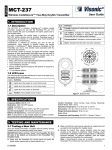
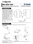
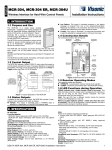
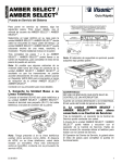
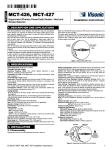
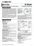
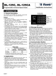
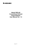
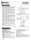
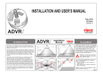
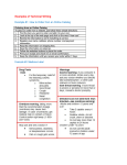
DISC MCW Installation Instructions Wireless PowerCode Digital Ceiling Mount PIR detector 1. INTRODUCTION The DISC MCW is the smallest 360 ceiling mounted passive infrared detector presently marketed. The DISC MCW is a microprocessor-controlled wireless digital PIR detector, designed for easy installation. The DISC MCW provides a nearly conical pattern of maximum 10.5 m (36 ft) diameter, when installed on a 3.6 m (12ft) ceiling. The advanced True Motion Recognition algorithm (patented) allows to distinguish between the true motion of an intruder and any other disturbances which may cause false alarms. False alarms caused by environmental disturbances are virtually eliminated with alternate polarity pulse counter signal processin g and a low-noise pyroelectric detector. Programmable motion event counter. Very low current consumption Tamper switch for detector opening. White light protection. Elegantly styled, sturdy case. The DISC MCW includes the following features: Provides multiple beams coverage. Incorporates a fully supervised PowerCode transmitter. Sophisticated frequency domain digital signal processing. Figure 1 – External View 2. SPECIFICATIONS Detector Type: Dual element low-noise pyroelectric sensor. ELECTRICAL Internal Battery: 3V Lithium battery, type CR-123A. For UL installations, use Panasonic, Sanyo or GP only. Nominal Battery Capacity: 1400 mA/h. Battery Life (with LED on): Typically over 3 years. Battery Power Test: Performed immediately upon battery insertion and periodically after every several hours. FUNCTIONAL True Motion Event Verification: 2 position selector - 1 (OFF) or 2 (ON) motion events. Visual Indications: LED Lights for about 3 seconds upon transmission of alarm & tamper messages and upon motion detection in the walk test mode. LED Flashes during the power-up stabilization period, or after restoring (pressing) the tamper switch. LED does not light upon transmission of supervision messages. Rearm Timer: Rearms the detector 2 minutes after the last motion detection. The detector reverts to the initial state if there is no movement during 2 minutes. The timer is disabled in the walk test mode. WIRELESS Frequency (MHz): 315 (U.S. version), 433.92, 868.95 or other frequency according to local requirements. Transmission Sequence: 3 data bursts at variable / random intervals within 3 seconds. Encoding: Over 16 million possible combinations. Total Message Length: 36 bits. Supervision Message: Signaling at 60-minute intervals (U.S. version). MOUNTING Ceiling Mounting: Maximum mounting height 3.6 m (12 ft) ENVIRONMENTAL RFI Protection: >10 V/m up to 2000 MHz. Operating Temperatures: -10°C to 50°C (14°F to 122°F). Storage Temperatures: -20°C to 60°C (-4°F to 140°F). Compliance with Standards: USA @ 315 MHz: complies with CFR 47 part 15 (FCC) and RSS210. Europe @ 433.92 or 969.95 MHz: EN 300220, EN 301489, EN 60950, EN 50131-2-2 Grade 1 Class II PHYSICAL Dimensions (diam. x H) : 86 x 24 mm (3-3/8 x 15/16 in). Weight: 64 grams (2 oz) Color: White. PATENTS U.S. Patents 5,693,943 6,818,881 (other patents pending). 2.4 m (8 ft) Side View (1 Pulse Setting) 7.3 m (24 ft) 3.6 m (12 ft) Side View (2 Pulse Setting) 10.8 m (36 ft) Top View Figure 2 - DISC MCW PIR Coverage Pattern D-302924 Disc MCW Installation Instructions 1 3. INSTALLATION 3.1 Mounting The DISC MCW PIR is installed on the ceiling. The maximum installation height is 3.6m (12 ft). A. Mount the unit so that the expected motion of an intruder is perpendicular to the detector and not in the direction of the detector. Be sure to install the detector on a stable ceiling, to avoid vibrations. Note: Passive infrared detectors are sensitive to changes in infrared energy caused by an object moving across the unit's field of view. Detection of changes in infrared energy depends on the amount of infrared energy transmitted by the moving object, and the temperature difference between the object and the background. Because of this the PIR may fail to respond under certain temperature and background conditions, in which the temperature difference is too small. B. The DISC MCW is extremely immune to air turbulence and RFl interference. COVER However, to minimize possible false alarms, it is highly recommended that you avoid aiming the detector at heaters, BASE sources of light, or windows subjected to direct sunlight. Avoid mounting the DISC MCW in locations where air drafts could flow from the ceiling or from close walls. Also avoid installation close to high power Figure 3 - Removing the electrical cables. Cover C. Hold the unit base as shown in Figure 3. Rotate the cover counter clockwise until it stops. Separate the cover from the base. Note: If the cover does not separate easily from the base, insert a 1/8" screwdriver between a tab (on the cover) and a slot (on the base). Lower the screwdriver handle until the base separates from the cover and removes easily. D. Mount the base (equipped with the printed circuit board) in the location selected for optimum coverage. Using the two mounting holes at the back of the base fasten the unit firmly to the mounting surface to avoid possible vibrations. (Figure 4). Line up the 3 tabs on the cover with the 3 slots on the base. Fit the cover over the base. Rotate Figure 4 – Installing the the cover clockwise until it stops. Cover 3.2 LED Functions After battery insertion and rear cover closure, the LED flashes for 2 minutes approximately until the detector stabilizes. After stabilization, the detector enters automatically walk-test period of 15 minutes (see section 3.6 Walk Test below). In this mode the LED lights and the unit sends an RF alarm signal on every detection (regardless of LED jumper position). After the walk-test period, the LED operates according to the LED jumper setting, as follows: 2 LED Jumper Position LED Activity in "Normal Mode" LED lights during alarm transmission. ON LED does not light during alarm transmission. OFF After the first 15 minutes, following every motion detection and alert transmission, the detector disarms itself to save battery power. It rearms (reverts to the ready state) if there is no subsequent detection during the following 2-minute period. Therefore, if you want to check the detector, you have to exit the room for at least 2 minutes and then enter the room. 3.3 Battery Insertion Insert battery (see Figure 5) – Verify proper polarity. Caution! Dispose of used battery according to manufacturer's instructions 3.4 Setting the Pulse Counter The DISC MCW is equipped with a selectable alternate polarity pulse counter which can be set to count two consecutive pulses with opposite polarity, before activating the alarm. Pulse count signal processing requires that the moving person will cross both elements of the dual detector before the alarm is activated. This provides maximum protection against false alarms caused by environmental disturbances. LED SELECTOR EVENT COUNTER SELECTOR WALK-TEST & ALARM LED TAMPER SWITCH MOUNTING HOLE MOUNTING HOLE DETECTOR BATTERY Figure 5 - Printed Circuit Board 2 pulse setting The two pulse logic may be selected only when the DISC MCW is installed in temperature controlled locations. 1 pulse setting This setting actually disables the pulse counter. It should be used when maximum detecting sensitivity or fast "catch" performance are of highest importance, such as in high security installations. 3.5 Enrolling In order that the PowerMax family control panels will identify the detector signal, perform enrolling as described in the PowerMax+ or PowerMax Pro installer guide, respectively. 3.6 Walk-Test After closing the cover and after the detector stabilization period (2 minutes approximately), the detector enters a 15 minute walktest mode. In this mode, the LED flashes each time a motion is detected, regardless of LED jumper settings and the detector transmits the occurrence of each event. Walk across the far end of the coverage pattern in both directions. The indicator should light for 3 seconds approximately each time your motion is detected. Important: Instruct the user to perform walk-test at least once a week to assure proper detector's function. D-302924 Disc MCW Installation Instructions 4. SPECIAL COMMENTS 4.1 Product Limitations Visonic Ltd. wireless systems are very reliable and are tested to high standards. However, due to their low transmitting power and limited range (required by FCC and other regulatory authorities), there are some limitations to be considered: A. Receivers may be blocked by radio signals on or near their operating frequencies, regardless of the code selected. B. A receiver can only respond to one signal at a time. C. Wireless equipment should be tested regularly to determine whether there are sources of interference and to protect against faults. D. Even the most sophisticated detectors can sometimes be defeated or may fail to warn due to: DC power failure / improper connection, malicious masking of the lens, tampering with the optical system, decreased sensitivity in ambient temperatures near that of the human body and unexpected failure of a component part. The above list includes the most common reasons for failure to detect intrusion, but is by no means comprehensive. It is therefore recommended that the detector and the entire alarm system be checked weekly, to ensure proper performance. E. An alarm system should not be regarded as a substitute for insurance. Home and property owners or renters should be prudent enough to continue insuring their lives and property, even though they are protected by an alarm system. This device complies with Industry Canada licence-exempt RSS standard(s). Operation is subject to the following two conditions: (1) this device may not cause harmful interference, and (2) this device must accept any interference, including interference that may cause undesired operation of the device. Le présent appareil est conforme aux CNR d'Industrie Canada applicables aux appareils radio exempts de licence. L'exploitation est autorisée aux deux conditions suivantes : (1) l'appareil ne doit pas produire de brouillage, et (2) l'utilisateur de l'appareil doit accepter tout brouillage radioélectrique subi, même si le brouillage est susceptible d'en compromettre le fonctionnement. 4.2 Compliance with Standards The digital circuit of this device has been tested and found to comply with the limits for a Class B digital device, pursuant to Part 15 of the FCC Rules. These limits are designed to provide reasonable protection against harmful interference in residential installations. This equipment generates uses and can radiate radio frequency energy and, if not installed and used in accordance with the instructions, may cause harmful interference to radio and television reception. However, there is no guarantee that interference will not occur in a particular installation. If this device does cause such interference, which can be verified by turning the device off and on, the user is encouraged to eliminate the interference by one or more of the following measures: – Re-orient or re-locate the receiving antenna. – Increase the distance between the device and the receiver. – Connect the device to an outlet on a circuit different from the one which supplies power to the receiver. – Consult the dealer or an experienced radio/TV technician. The 315 MHz version of this device complies with Part 15 of the FCC Rules. Operation is subject to the following two conditions: (1) This device may not cause harmful interference, and (2) This device must accept any interference received, including interference that may cause undesired operation. WARNING! Changes or modifications to this unit not expressly approved by the party responsible for compliance could void the user's authority to operate the equipment. 4.3 Frequency Allocations for Wireless Devices in European (EU) Countries 315 MHz is not allowed in any EU member state. 433.92 MHz has no restriction in any EU member state. 868.95 MHz (wide band) is allowed in all EU member states. 869.2625 MHz (narrow band) is not restricted in any EU member state. 4.4 Battery Handling A. Replace battery ONLY with recommended battery (see specifications). B. Dispose used batteries according to their manufacturer's instructions. D-302924 Disc MCW Installation Instructions 3 WARRANTY Visonic Limited (the “Manufacturer") warrants this product only (the "Product") to the original purchaser only (the “Purchaser”) against defective workmanship and materials under normal use of the Product for a period of twelve (12) months from the date of shipment by the Manufacturer. This Warranty is absolutely conditional upon the Product having been properly installed, maintained and operated under conditions of normal use in accordance with the Manufacturers recommended installation and operation instructions. Products which have become defective for any other reason, according to the Manufacturers discretion, such as improper installation, failure to follow recommended installation and operational instructions, neglect, willful damage, misuse or vandalism, accidental damage, alteration or tampering, or repair by anyone other than the manufacturer, are not covered by this Warranty. The Manufacturer does not represent that this Product may not be compromised and/or circumvented or that the Product will prevent any death and/or personal injury and/or damage to property resulting from burglary, robbery, fire or otherwise, or that the Product will in all cases provide adequate warning or protection. The Product, properly installed and maintained, only reduces the risk of such events without warning and it is not a guarantee or insurance that such events will not occur. THIS WARRANTY IS EXCLUSIVE AND EXPRESSLY IN LIEU OF ALL OTHER WARRANTIES, OBLIGATIONS OR LIABILITIES, WHETHER WRITTEN, ORAL, EXPRESS OR IMPLIED, INCLUDING ANY WARRANTY OF MERCHANTABILITY OR FITNESS FOR A PARTICULAR PURPOSE, OR OTHERWISE. IN NO CASE SHALL THE MANUFACTURER BE LIABLE TO ANYONE FOR ANY CONSEQUENTIAL OR INCIDENTAL DAMAGES FOR BREACH OF THIS WARRANTY OR ANY OTHER WARRANTIES WHATSOEVER, AS AFORESAID. THE MANUFACTURER SHALL IN NO EVENT BE LIABLE FOR ANY SPECIAL, INDIRECT, INCIDENTAL, CONSEQUENTIAL OR PUNITIVE DAMAGES OR FOR LOSS, DAMAGE, OR EXPENSE, INCLUDING LOSS OF USE, PROFITS, REVENUE, OR GOODWILL, DIRECTLY OR INDIRECTLY ARISING FROM PURCHASER’S USE OR INABILITY TO USE THE PRODUCT, OR FOR LOSS OR DESTRUCTION OF OTHER PROPERTY OR FROM ANY OTHER CAUSE, EVEN IF MANUFACTURER HAS BEEN ADVISED OF THE POSSIBILITY OF SUCH DAMAGE. THE MANUFACTURER SHALL HAVE NO LIABILITY FOR ANY DEATH, PERSONAL AND/OR BODILY INJURY AND/OR DAMAGE TO PROPERTY OR OTHER LOSS WHETHER DIRECT, INDIRECT, INCIDENTAL, CONSEQUENTIAL OR OTHERWISE, BASED ON A CLAIM THAT THE PRODUCT FAILED TO FUNCTION. However, if the Manufacturer is held liable, whether directly or indirectly, for any loss or damage arising under this limited warranty, the Manufacturer's maximum liability (if any) shall not in any case exceed the purchase price of the Product, which shall be fixed as liquidated damages and not as a penalty, and shall be the complete and exclusive remedy against the Manufacturer. When accepting the delivery of the Product, the Purchaser agrees to the said conditions of sale and warranty and he recognizes having been informed of. Some jurisdictions do not allow the exclusion or limitation of incidental or consequential damages, so these limitations may not apply under certain circumstances. The Manufacturer shall be under no liability whatsoever arising out of the corruption and/or malfunctioning of any telecommunication or electronic equipment or any programs. The Manufacturers obligations under this Warranty are limited solely to repair and/or replace at the Manufacturer’s discretion any Product or part thereof that may prove defective. Any repair and/or replacement shall not extend the original Warranty period. The Manufacturer shall not be responsible for dismantling and/or reinstallation costs. To exercise this Warranty the Product must be returned to the Manufacturer freight pre-paid and insured. All freight and insurance costs are the responsibility of the Purchaser and are not included in this Warranty. This warranty shall not be modified, varied or extended, and the Manufacturer does not authorize any person to act on its behalf in the modification, variation or extension of this warranty. This warranty shall apply to the Product only. All products, accessories or attachments of others used in conjunction with the Product, including batteries, shall be covered solely by their own warranty, if any. The Manufacturer shall not be liable for any damage or loss whatsoever, whether directly, indirectly, incidentally, consequentially or otherwise, caused by the malfunction of the Product due to products, accessories, or attachments of others, including batteries, used in conjunction with the Products. This Warranty is exclusive to the original Purchaser and is not assignable. This Warranty is in addition to and does not affect your legal rights. Any provision in this warranty which is contrary to the Law in the state or country were the Product is supplied shall not apply. Warning:The user must follow the Manufacturer’s installation and operational instructions including testing the Product and its whole system at least once a week and to take all necessary precautions for his/her safety and the protection of his/her property. 1/08 W.E.E.E. Product Recycling Declaration For information regarding the recycling of this product you must contact the company from which you orignially purchased it. If you are discarding this product and not returning it for repair then you must ensure that it is returned as identified by your supplier. This product is not to be thrown away with everyday waste. Directive 2002/96/EC Waste Electrical and Electronic Equipment. EMAIL: [email protected] INTERNET: www.visonic.com VISONIC LTD. 2014 DISC MCW 4 D-302924 (Rev 3, 6/14) D-302924 Disc MCW Installation Instructions