1
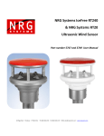
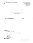
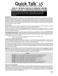
HD5 Hardi Europe AutoSlant DAH or DAH09 Installation Manual Printed in Canada Copyright 2012 by NORAC Systems International Inc. Reorder P/N: UC4.5-BC-HD5-INST Rev B (Hardi Europe AutoSlant DAH or DAH09) NOTICE: NORAC Systems International Inc. reserves the right to improve products and their specifications without notice and without the requirement to update products sold previously. Every effort has been made to ensure the accuracy of the information contained in this manual. The technical information in this manual was reviewed at the time of approval for publication. Contents 1 Introduction ................................................................................................................ 1 2 General UC4.5 System Layout ................................................................................. 2 3 Kit Parts ...................................................................................................................... 3 4 Existing System Check .............................................................................................. 6 5 Ultrasonic Sensor Installation .................................................................................. 7 6 Electrical Installation ............................................................................................... 14 7 Software Setup ......................................................................................................... 22 8 Cable Drawings ........................................................................................................ 23 1 Introduction Congratulations on your purchase of the NORAC UC4.5 Spray Height Control System. This system is manufactured with top quality components and is engineered using the latest technology to provide operating reliability unmatched for years to come. When properly used the system can provide protection from sprayer boom damage, improve sprayer efficiency, and ensure chemicals are applied correctly. Please take the time to read this manual completely before attempting to install the system. A thorough understanding of this manual will ensure that you receive the maximum benefit from the system. Your input can help make us better! If you find issues or have suggestions regarding the parts list or the installation procedure, please don’t hesitate to contact us. Every effort has been made to ensure the accuracy of the information contained in this manual. All parts supplied are selected to specially fit the sprayer to facilitate a complete installation. However, NORAC cannot guarantee all parts fit as intended due to the variations of the sprayer by the manufacturer. Please read this manual in its entirety before attempting installation. 1 2 General UC4.5 System Layout Figure 1illustrates the general layout of the UC4.5 system components: Figure 1: General UC4.5 System Layout 2 3 3.1 Kit Parts Kit Overview Cables C12A and C13 may be used in place of Cable C12 in some installations. Figure 2: HD5 System Parts 3 3.2 List of Parts Item Part Number Name Quantity B06 105728 RAM-233 RAIL MOUNT ADAPTER KIT FOR RAM-202 BASE 1 B10 44728 MOUNTING BRACKET COMPLETE UC4 BREAKAWAY EXTENDED 2 C05 43210-20 CABLE UC5 NETWORK 18 AWG 20M 2 C10 44650-52 CABLE UC4.5 POWER HARDI 1 C11 44651-51 CABLE UC4.5 EXTENSION VALVE HARDI 1 C12 44658-78 CABLE INTERFACE HARDI DAH09 1 C12A 44658-51 CABLE UC4 INTERFACE HARDI 1 C13 44782 CONN GP TOWER PLUG 6 WAY 2 E01 45100 UC4.5 BOOM CONTROL PANEL 1 E05 43750 UC5 ULTRASONIC SENSOR 2 E10 43760 UC5 NETWORK COUPLER 3-WAY 1 E20 43764T UC5 NETWORK COUPLER 2-WAY WITH TERMINATOR 2 M01 UC4.5-BC-MANUALOPERATOR OPERATOR MANUAL UC4.5 SPRAY HEIGHT CONTROL 1 M02 UC4.5-BC-HD5-INST MANUAL INSTALLATION UC4.5 HARDI EUROPE AUTOSLANT DAH OR DAH09 1 M03 UC4.5-BC-HD5-INSTE MANUAL INSTALLATION UC4.5 END USER HARDI EUROPE AUTOSLANT 1 4 3.3 Hardi Supplied Parts The required HARDI parts necessary for the installation are listed in Table 1. Table 1: HARDI Parts Item Part Number Name Quantity HARDI04 262126 LIQUIDTIGHT CONNECTOR 1 HARDI05 262107 LIQUIDTIGHT CONNECTOR NUT 1 HARDI06 284846 CABLE TIES 175 Item HARDI04 and HARDI05 are only required when using the 44658-51 (C12A) interface harness. Table 2: HARDI Parts for Aluminum (Round) Booms Item Part Number HARDI07 ------ Name ROUND TUBE CLAMPS FOR MOUNTING TO ALUMINUM BOOMS Quantity 4 Items numbers followed with an asterisks are to be delivered to the sprayer End-User. These parts require installation to the tractor unit in accordance to the accompanied documentation. Do not use high speed power tools/drills when installing hardware. The use of dielectric grease is not recommended on any NORAC electrical connections. To ensure all stainless steel hardware does not gall or seize apply a light coating of the supplied Permatex Anti-seize grease to all threaded parts upon installation. Permatex Anti-seize lubricant is preferred, but other similar anti-seize products may be used. 5 4 Existing System Check 1. Before beginning the install, ensure all hydraulic boom functions are operating properly on the sprayer. All Fold Functions Main Lift Function Wing Tilt Functions Slant Function 2. Inspect slide pads and wear surfaces for excessive wear. Replace or adjust if necessary. 3. Ensure the boom guide-rods are set to the “tapered” position (factory setting). 4. Set boom suspension to be critically damped (Figure 3). Adjust the boom damper accordingly. a. Unlock the pendulum, and push boom tip down approximately 75 cm (30 inches). b. Hold the boom steady for a moment, and release. c. Ensure the boom returns to its relaxed state as quickly as possible, with little to no overshoot. Figure 3: Boom Push Test- Critically Damped 6 5 5.1 Ultrasonic Sensor Installation Bracket Assembly Assemble the breakaway sensor bracket as illustrated in Figure 4, following the instructions below. Figure 4: Breakaway Bracket Assembly 1. Compress the spring and insert it together with the collar into the base. 2. Slide the tube through the assembled part. 3. Using the bolt and nut, tighten the collar to the tube with the sensor tube centered. 4. Apply a small amount of grease to the rotating surfaces of the bracket. 7 5.2 Ultrasonic Sensor Serial Number Arrangement When installing the sensors, start with the smallest serial number on the left-hand side, and proceed to the largest serial number on the right hand side. Each sensor has a serial number stamped on the sensor housing. Apply a light coating of the supplied Permatex Anti-seize grease to all threaded parts upon installation. Figure 5: Sensor Serial Number Arrangement 8 5.3 Ultrasonic Sensor Mounting Guidelines The following guidelines will ensure optimal sensor performance and prevent sensor measurement error. These rules should be followed for both the wing sensors and the main lift (middle) sensor. 1. In its lowest position, the sensor must be 9 inches (23 cm) or more from the ground (A). 2. The centerline of the acoustic cone should be approximately vertical at normal operating heights (A). 3. The bottom of the sensor must be at least 9 inches in front of the spray nozzles and boom structure (B). (This does not apply for the main lift sensor) 4. The bottom of the sensor must be at least 9 inches above the spray nozzles (C). 5. Ensure there are no other obstructions with a 12 inch (23 cm) diameter circle projected directly below the sensor (D). 6. The sensor bracket should be oriented forward (ahead of the boom). 7. Mount the NORAC ultrasonic sensor into the sensor bracket and run the sensor cable through the sensor tube. A problem can arise if a sensor is not mounted correctly. It is possible for the sensor to read off of the boom instead of the ground. This may only become apparent once the control system is switched from soil to crop mode. Also be careful that the sensor bracket does not collide with any other part of the boom when the boom is folded to transport position. If possible, mount the sensor brackets while the booms are folded to ensure they will not cause interference. Figure 6: Sensor Mounting Guidelines 9 Figure 7: Sensor Reading Off Boom 5.4 Wing Bracket Mounting on HPZ (24-36m) /HAZ (18-30m) Below is the suggested mounting location for the wing sensor brackets on the HPZ (24-36m) or HAZ (18-30m) booms. Mounting location is just inside of the boom break-away section (A). (B) (A) (B) (A) Figure 8: Suggested Bracket Mounting Location (viewed from front) on 24m HAZ IMPORTANT: Avoid mounting the bracket too close to the touch-down wheel (B). 10 5.5 Wing Bracket Mounting on HAZ (32-36m) Boom Below is the suggested mounting location for the wing sensor brackets on the HAZ 32-36m booms. Mounting location is just inside of the boom break-away section (A). (A) Figure 9: Suggested UC4 Bracket Mounting Location (viewed from front) on 36m HAZ 11 5.6 Wing Bracket Mounting on LPZ Below is the suggested mounting location for the wing sensor brackets on the LPZ boom. Mounting location is just inside of the boom break-away section (A). (A) (A) Figure 10: Suggested Bracket Mounting Location on LPZ Boom 12 5.7 Round Profile Aluminum Booms Mount the sensor bracket using round tube clamps (item HARI07), near the spring for the tip breakaway. Ensure the bracket does not rotate downwards with vibration. Mounting location is just inside of the boom break-away section (A). Figure 11: Suggested UC4 Bracket Mounting Location (A) Figure 12: Another Acceptable Mounting Location 13 6 Electrical Installation Ensure the UC4.5 Control Panel is OFF for the remainder of the installation (Bottom of switch pressed IN). Use caution when handling the 12 V power line of the sprayer wiring. Depending on the electronics used on the sprayer (DAH or DAH09), either the NORAC part 44658-51 or 44658-78 will be required for this installation. For installations using 44658-51, proceed to section 6.1. For installations using the 44658-78 proceed to section 6.2. Figure 13: HARDI DAH on left (use 44658-51) vs. DAH09 interface on right (use 44658-78) 14 6.1 General Installation Instructions using 44658-51 Figure 14: Cable Overview (Using 44658-51) 1. Connect the UC4.5 power cable (C10) to the UC4.5 Control Panel in the cab. Ensure that both plugs (P16 and P4) are connected to the panel. Cable tie C10 to the RAM mount to help provide strain relief. 2. Route the P12/P6 of C10 to the exterior of the cab. 3. Connect P12/P6 to R12/R6 of the extension cable (C11). connection will provide the hitch disconnect. Connect at the hitch. This 4. Run cable C11 from the hitch to the rear of the sprayer. 5. Route the 6-pin and 4-pin tower connectors (T6 and T4) of C11 in the vicinity of the Jobcom box. Ensure power to the Job-com is turned off. 6. If the sprayer uses one forward/reverse valve and a number of cartridge valves (HARDI DH) turn ON the DIP switch of C12A (Figure 15). Otherwise leave the switches OFF (HARDI DAH). There is denotation on the switch. Turn BOTH switches either ON or OFF. 15 ON Figure 15: 44658-51 Interface Board Configuration Switch Figure 16: DAH valve (left) and DH valve (right) If the switch is not turned on for DH hydraulics, the boom slant will not function. 7. Connect the NORAC C12A between the J4 connection on the HARDI PCB and the blue wiring harness. a) Remove the blue harness from J4 (37-pin DB male socket) on the PCB inside of the Jobcom. b) Insert the 37-pin DB female socket on the PCB of the interface cable (C12A) into J4. Screw it down to J4. This requires removing the small nuts on the DB-37 connector. c) Insert the blue-wire harness into the 37-pin DB male socket on the other side of the PCB of C12A. Screw it down to the socket. 16 Figure 17: J1, J2 and J4 on HARDI DAH Board Do not connect spade connectors to J1 & J2 until step 8. 8. Run the free end of C12A through an unused hole of the electronics enclosure. This requires installing the Liquidtight connector (Pt. HARDI04, HARDI05) BEFORE proceeding to step 9. 9. Put pins of C12A to the 6-pin and 4-pin Weatherpack connectors (S6 and S4) which are included in this kit according to the table below. One connector on harness C11 may by unused. Seal the unused connector with a 6-pin plug (C13). The wire colors and the pin-out are the same as ones on the mating connectors (T6 and T4) of the extension cable (C11). 17 6.2 General Installation Instructions using 44658-78 Figure 18: Cable Overview (Using 44658-78) 1. Connect the UC4.5 power cable (C10) to the UC4.5 Control Panel in the cab. Ensure that both plugs (P16 and P4) are connected to the panel. 2. Route the P12/P6 of C10 to the exterior of the cab. 3. Connect P12/P6 to R12/R6 of the extension cable (C11). connection will provide the hitch disconnect. Connect at the hitch. This 4. Run cable C11 from the hitch to the rear of the sprayer. 5. Connect T4, T6 and S6 of cable C11 to S4, S6 and T6 of cable C12 respectively. 6. Run the DB15 connector and the wires with the spade connectors of C12 to the DAH 09 PCB by passing it through a hole in the enclosure. Seal the hole using the weather-proof strain relief fitting. 7. Connect the DB15 connector of cable C12 to the DAH09 DB15 connector. 8. Connect the red wire with spade connector on C12 to the Switched 12VCC on the DAH09 board (Figure 19). 9. Connect the black wire with spade connector on C12 to the GND on the DAH09 board (Figure 19). 18 12 VDC and GND DB15 DIP switches Figure 19: DAH09 PCB for AutoHeight 10. Configure the system for Autoslant by setting the DIP switches on DAH09 board: a) Set DIP switches 2,3,4,6 and 8 to ON. Set DIP switch 5 and 7 to OFF (Figure 20). Figure 20: Suggested Default Setting for DIP Switches 2-8 for AUTOSLANT b) If the sprayer uses a DAH valve block set DIP switch 1 to OFF. If the sprayer uses a DH valve block set DIP switch 1 to ON. See Figure 21. 11. Close the electronics enclosure. Gather up excess cable (C11 & C02) and neatly cable-tie to the machine. Figure 21: HARDI DAH (DIP 1 OFF) vs. DH Block (DIP 1 ON) 19 Notice: Additional instructions are available in the UC4.5-BC-HD5-INSTE (End-user manual) for configuring spray ON/OFF signal sensing and headland modes. With these features the Autoslant system will function together with the spray signal, switching boom height control on and off with the spray signal. This function can also be configured to raise the boom automatically for headland turning. Refer to the HD5 end-user manual for more information. These additional features described are only available when using the HARDI DAH09 PCB. This is only applicable for systems using the DAH09 interface and with harness 44658-78. * Note that on some sprayers the slant valve wiring varies from machine to machine. This applies to all machines. If the left-hand tip lifts when the left button is pressed and the right-hand button lifts the right hand tip (Figure 22), the wiring as described above is correct. Figure 22: Default Slant Direction Wiring However, if the boom does the opposite of what is described above, it is necessary to swap the E and F wires in the S6 connector of 44658-78 (C12) or 44658-51 (C12A). 20 6.3 NORAC Sensor Connections 1. Fasten the 8-way coupler to the boom with cable ties. Connect P6 on C11 to the 3-way coupler. 2. Connect two cables (C05) to the 3-way coupler and route along the booms to the wing sensors. Follow existing cables and hoses to be sure the cable will not be pinched or stretched. 3. At the sensor brackets, attach a 2-way coupler with terminator (E20) to the sprayer boom. The 2-way coupler with terminator is the white two way coupler. Plug the sensor and the CANbus cable into the 2-way coupler. IMPORTANT: Provide enough slack in all cables to account for the movement of the main section, parallel lift, and FOLDING boom movement. 21 7 Software Setup 1. Test the functionality of the original manufacturer’s boom controls. Power to the NORAC control panel does not need to on be for the sprayer controls to function. Unfold the booms and raise/lower each boom and main section. If one or more of these functions do not work, review the hydraulic and electrical portions of this manual to check for proper installation. 2. Confirm that the cabling/hoses are at agreeable lengths for the entire range of motion. 3. Prepare the spray boom for the software installation. Unfold the booms and level to 90 cm (or 35 inch) nozzle height. Ensure the boom slant is in its centered position. At this point ensure the UC4.5 sensors are reading from an adequate and uniform target, such as gravel or dirt. Do not attempt to perform the installation over grass or crop. If the installation is done over concrete, place carpet beneath the sensors to avoid sensor problems during the installation. 4. Switch on the UC4.5 control panel and select the HD5 sprayer type. 5. At this point two install options are available: a. Complete Install - this will setup the entire AutoSlant system, requiring fully range of boom moment. Hydraulics will be calibrated to the hydraulic power unit connected. and follow the on screen instructions. To perform a complete install, press b. Quick Install - this will require the boom to be unfolded at 90cm spray height but no hydraulic movement will occur (hydraulic calibration will occur at a later time by performing a “Retune” on the final hydraulic power unit. To perform a Quick Install, until “SENSOR” appears on the screen and release. Follow the on press and hold screen instructions. 6. Refer to the UC4.5 Operators Manual for more detail. 22 8 8.1 23 Cable Drawings ITEM C05: 43210-20 - CABLE UC5 NETWORK 18 AWG - 20M 8.2 ITEM C10: 44650-52 - CABLE UC4.5 POWER HARDI 24 8.3 25 ITEM C11: 44651-51 - CABLE UC4.5 EXTENSION VALVE HARDI 8.4 ITEM C12: 44658-78 - CABLE UC4 BC INTERFACE HARDI DAH09 26 8.5 27 ITEM C12A: 44658-51 – CABLE UC4 BC INTERFACE HARDI DAH Canada NORAC Systems International Inc. Phone: (+1) 306 664 6711 Toll Free: 1 800 667 3921 Shipping Address: 3702 Kinnear Place Saskatoon, SK S7P 0A6 United States NORAC, Inc. Phone: (+1) 952 224 4142 Toll Free: 1 866 306 6722 Shipping Address: 6667 West Old Shakopee Road, Suite 111 Bloomington, MN 55438 Europe NORAC Europe sarl Phone: (+33) 04 26 47 04 42 Shipping Address: Rue de l’hermitage 01090 Guereins France www.norac.ca