1
EU1
Generic Unit - Europe
Variable Geometry with Slant Control
Installation Manual
Printed in Canada
Copyright 2012 by NORAC Systems International Inc.
Reorder P/N: UC4.5-BC-EU1-INST Rev A (Generic Unit – Variable Geometry with Slant
Control - Europe)
NOTICE: NORAC Systems International Inc. reserves the right to improve products and their specifications without notice and
without the requirement to update products sold previously. Every effort has been made to ensure the accuracy of the information
contained in this manual. The technical information in this manual was reviewed at the time of approval for publication.
Contents
1 Introduction ................................................................................................................ 1 2 General UC4.5 System Layout ................................................................................. 2 3 Kit Parts ...................................................................................................................... 3 4 Installation Style......................................................................................................... 6 5 Ultrasonic Sensor Installation ................................................................................ 10 6 Roll Sensor Installation............................................................................................ 15 7 Electrical Installation ............................................................................................... 21 8 Hydraulic Installation .............................................................................................. 25 9 Software Setup ......................................................................................................... 30 10 Calibrating the Slant Valve ..................................................................................... 31 11 Cable Drawings ........................................................................................................ 34 1
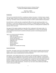
Introduction
Congratulations on your purchase of the NORAC UC4.5 Spray Height Control System. This
system is manufactured with top quality components and is engineered using the latest
technology to provide operating reliability unmatched for years to come.
When properly used the system can provide protection from sprayer boom damage, improve
sprayer efficiency, and ensure chemicals are applied correctly.
Please take the time to read this manual completely before attempting to install the system. A
thorough understanding of this manual will ensure that you receive the maximum benefit from
the system.
Your input can help make us better! If you find issues or have suggestions regarding the parts
list or the installation procedure, please don’t hesitate to contact us.
Every effort has been made to ensure the accuracy of the information contained in
this manual. All parts supplied are selected to specially fit the sprayer to facilitate
a complete installation. However, NORAC cannot guarantee all parts fit as
intended due to the variations of the sprayer by the manufacturer.
Please read this manual in its entirety before attempting installation.
1
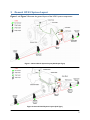
2
General UC4.5 System Layout
Figure 1 and Figure 2 illustrate the general layout of the UC4.5 system components:
Figure 1: General UC4.5 System Layout (Self Propel Type)
Figure 2: General UC4.5 System Layout (Pull Type)
2
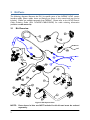
3
Kit Parts
The following diagrams illustrate the EU1 kit specific parts of the NORAC UC4.5 system.
Interface cables, power cables, hoses and fittings are shown in this manual and may not be
included. Cables are available separately from NORAC. Please refer to the UC4.5 Generic
Cable Ordering Guide (P/N: UC4.5-BC-CABLE-GUIDE) for cable ordering information
(available at www.norac.ca).
3.1
Kit Overview
Figure 3: EU1 System Parts
NOTE:
3
Parts shown in blue are NOT included in this kit and must be ordered
separately.
3.2
List of Parts
Item
Part Number
Name
Quantity
B05
44706-01
KIT CABLE TIE BLACK 10 PCS 21 IN 150 PCS 7.5 IN
1
B20
44971
SENSOR MOUNTING BRACKET LOW PROFILE 16GA
2
B21
44973
SENSOR MOUNTING BRACKET LOW PROFILE 16 GA LARGE FLANGE
1
C03
44656D
CABLE VALVE VARIABLE RATE DT
1
C05
43210-20
CABLE UC5 NETWORK 18 AWG 20M
2
C07
43220-01
CABLE UC5 NETWORK 14 AWG 1M
1
C10
44650-51
CABLE UC4.5 POWER GENERIC PULL-TYPE
1
C11
44651-50
CABLE UC4.5 EXTENSION VALVE GENERIC
1
C30
43250-06
CABLE UC5 BATTERY PIGTAIL FUSED - 5A
1
E01
45100
UC4.5 BOOM CONTROL PANEL
1
E03
43742
UC5 ROLL SENSOR W TEMPERATURE PROBE
1
E04
43741
UC5 ROLL SENSOR VER. 2
1
E05
43750
UC5 ULTRASONIC SENSOR
3
E11
43765
UC5 NETWORK COUPLER 8-WAY
1
E12
43764
UC5 NETWORK COUPLER 2-WAY
1
E20
43764T
UC5 NETWORK COUPLER 2-WAY WITH TERMINATOR
2
H10
44865-34
HYDRAULICS FITTING KIT - GN1
1
M01
UC4.5-BC-MANUALOPERATOR
OPERATOR MANUAL UC4.5 SPRAY HEIGHT CONTROL
1
M02
UC4.5-BC-EU1-INST
MANUAL INSTALLATION UC4.5 GENERIC VARIABLE GEOMETRY - EUROPE
1
M06
45015
ANTI-SEIZE LUBRICANT KIT
1
P03
105882
UC5 NETWORK 6 PIN PLUG
2
V01
44963D
VALVE BLOCK ASSEMBLY 2 STATION CC/LS PROP DT 4 BOLT
1
4
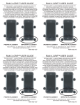
3.3
Item
Hydraulic Fitting Kit Details (P/N: 44865-34)
Part Number
Name
F07
103312
MALE ADAPTER - 6MB 6MJ
6
F08
44928
ORIFICE INSERT .047 IN ONE WAY
4
F09
104369
PLUG - 6MBP
2
Fitting Name
Example:
Quantity
Picture
6 M B - 6 M OR X 90
SIZE IN
1/16TH'S
GENDER: MALE
OR FEMALE
TYPE:
B - ORB
J - JIC
OR - FLAT
FACE
P - PIPE
90° ANGLE
SWIVEL
TYPE
GENDER
SIZE
This fittings kit is designed for either single acting or double acting hydraulics. Not
all fittings are used for each installation.
The use of dielectric grease is not recommended on any NORAC electrical
connections.
To ensure all stainless steel hardware does not gall or seize apply a light coating of
the supplied Permatex Anti-seize grease (M06) to all threaded parts upon
installation. Permatex Anti-seize lubricant is preferred, but other similar anti-seize
products may be used.
5
4
Installation Style
This install may require additional electrical/hydraulic components.
NOT proceed with install until all parts are available.
Do
In general, there are two styles of installation that can be done with the NORAC UC4.5 Spray
Height Control system: Electrically Teed Installation and Hydraulically Teed Installation.
4.1
Electrically Teed Installation
Electrically Teed Installation is the preferred style of installation. However, this style can be
done only if the sprayer valve block has individual electrical wiring to control each boom
function (e.g. left up, left down, right up, right down, main up, and main down).
Figure 4 and Figure 5 show the Electrically Teed installation in its general
installation configuration.
Figure 4: Electrical Wiring Applicable for Electrically Teed Installation
6
Figure 5: Hydraulic Components: Electrically Teed Installation
7
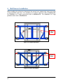
4.2
Hydraulically Teed Installation
Hydraulically Teed Installation must be done if the sprayer valve block does NOT have
individual electrical wiring to control each boom function. For example, the sprayer may have
signal lines to select a boom (left, right and main) and separate electrical signals for the
direction (up and down).
For Hydraulically Teed Installation, MANUAL mode of the UC4.5 Control System does not
operate the same as with Electrically Teed Installation. Electrically Teed Installation will allow
the operator to trigger individual boom movements into MANUAL mode while maintaining
AUTO mode for the other boom movements (e.g. left boom can be in MANUAL mode
while right boom is still in AUTO mode). Hydraulically Teed Installation does not support this
function. If the operator triggers any boom movement, the whole NORAC system will convert
to MANUAL mode.
Hydraulically Teed Installation may also be done if the operator wants the
existing sprayer valves, instead of the NORAC valves, to operate the booms
when the NORAC system is in MANUAL mode.
Figure 6 and Figure 7 show the Hydraulically Teed Installation in its general
installation configuration.
Figure 6: Typical Electrical Wiring for Hydraulically Teed Installation
8
Figure 7: Hydraulic Components: Hydraulically Teed Installation
9
5
5.1
Ultrasonic Sensor Installation
Ultrasonic Sensor Serial Number Arrangement
When installing the UC5 sensors, start with the smallest serial number on the left-hand side,
and proceed to the largest serial number on the right hand side. Each UC5 sensor has a serial
number stamped on the sensor housing.
Apply a light coating of the supplied Permatex Anti-seize grease (M06) to all
threaded parts upon installation.
Figure 8: Sensor Serial Number Arrangement
10
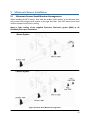
5.2
Ultrasonic Sensor Mounting Guidelines
The following guidelines will ensure optimal sensor performance and prevent sensor
measurement error. These rules should be followed for both the wing sensors and the main
lift (middle) sensor.
1. In its lowest position, the sensor must be 9 inches (23 cm) or more from the ground.
2. Ensure that there are no obstructions within a 12-inch diameter circle projected directly
below the center of the sensor.
3. The sensor should be approximately vertical at normal operating heights.
Figure 9: Sensor Mounting Guidelines
11
5.3
Low Profile Bracket Mounting Guidelines
1. Minimize the distance between the bolts to prevent bending the bracket and prevent the
bracket from loosening over time.
2. Ensure the bracket is mounted tight against the bottom of the boom, minimizing the
distance between the boom structure and the angled flange.
Figure 10: Bracket Mounting Guidelines
A problem can arise if a sensor is not mounted correctly. It is possible for the
sensor to read off of the boom instead of the ground. This may only become
apparent once the control system is switched from soil to crop mode.
Also be careful that the sensor bracket does not collide with any other part of the
boom when the boom is folded to transport position. If possible, mount the sensor
brackets while the booms are folded to ensure they will not cause interference.
12
5.4
Wing Sensor Installation
1. The wing sensor mounting brackets (B20) are the two brackets with the shorter mounting
flange.
2. The sensor bracket should be oriented forward (ahead of the boom).
3. Typically the best mounting location for the wing sensor brackets will be near the end of
the boom tips, approximately two feet (60cm) from the end.
4. Depending on the boom design, some breakaway sections will lift upwards as they break
back. If the sensor is mounted to this portion of the boom, the system will force the boom
downwards towards the ground as the boom folds backwards.
5. Mount the NORAC ultrasonic sensor into the sensor bracket and run the sensor cable
either through hole in the back or through the side cut-out and behind the bracket. Ensure
the cable is clear of moving parts and will not be damaged during folding.
Front
Figure 11: Bracket Mounting Example
13
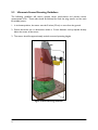
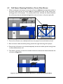
5.5
Main Lift Sensor Installation
1. The main lift mounting bracket (B21) is the bracket with the longer mounting flange.
2. There are a variety of ways to mount the main lift bracket on most sprayers. The bracket
should position the sensor approximately in the center of the sprayer, forward of the
boom. An example of this mounting is illustrated in Figure 13.
Front
Figure 12: Bracket Mounting Example
3. Mount the ultrasonic sensor to the main lift bracket. Run the sensor cable through hole
and behind the bracket.
Figure 13: Example Mounting of the Main Lift Bracket
Avoid mounting the main lift sensor over or near a wheel-track. Measurements
from the wheel-track do not provide an accurate crop height and will cause
measurement and control error.
Ensure the bracket does not collide with any other part of the sprayer throughout
the full range of main lift motion.
14
6
Roll Sensor Installation
Before installing the roll sensors, determine if the sprayer has a trapeze style, center pivot style
or high pendulum style boom. For installation on a trapeze style boom refer to Section 6.2.
For installation on a center pivot boom refer to Section 6.3. For installation on a high
pendulum boom refer to Section 6.4
Trapeze
Links
Figure 14: Trapeze Style Boom
Center
Pivot
Figure 15: Center Pivot Boom
15
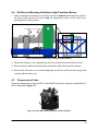
Figure 16: High Pendulum Boom
16
6.1
Bracket Assembly
1. Securely mount the roll sensors to the included roll sensor brackets using the #6 machine
screw.
2. The orientation of the mounted roll sensor to the roll sensor bracket will depend on the
bracket mounting. The roll sensor CANbus connector must be pointing towards the right
side of the sprayer (when looking from the rear of the sprayer).
Figure 17: Mounting Roll Sensor to Bracket
Figure 18: Roll Sensor Orientation - Connector Facing Right Wing
17
6.2
Roll Sensor Mounting Guidelines: Trapeze-Suspended Booms
1. When mounting the roll sensors, mount the roll sensor without the temperature probe on
the trapeze link (boom frame) and the roll sensor with the temperature probe on the
trapeze support (chassis). For optimal performance, minimize the distance from the boom
frame roll sensor to the pivot point (A) and minimize the vertical distance between the
chassis roll sensor and the pivot point (B).
Figure 19: Roll Sensor Mounting on a Trapeze Suspended Boom
2. Ensure the roll sensors are relatively level when the sprayer boom and chassis are level.
3. Both roll sensor cables should be pointing towards the right hand wing of the sprayer.
4. Ensure both roll sensors are mounted adequately and that the cables provide enough slack
to allow sufficient boom roll.
18
6.3
Roll Sensor Mounting Guidelines: Center Pivot Booms
1. When mounting the roll sensors, mount the roll sensor without the temperature probe on
the boom frame and the roll sensor with the temperature probe on the chassis (nonpivoting portion of the sprayer). For optimal performance, minimize the distance between
the roll sensors (A) and minimize the height from each roll sensor to the pivot point (B).
Figure 20: Roll Sensor Mounting on a Center Pivot Suspended Boom
2. Ensure the roll sensors are relatively level when the sprayer boom and chassis are level.
3. Both roll sensor cables should be pointing towards the right hand wing of the sprayer.
4. Ensure both roll sensors are mounted adequately and that the cables provide enough slack
to allow sufficient boom roll.
5. The chassis roll sensor can also be mounted inverted to minimize the distance between the
roll sensors (Figure 21).
Figure 21: Inverted Chassis Roll Sensor Mounting on a Center Pivot Suspended Boom
19
6.4
Roll Sensor Mounting Guidelines: High Pendulum Booms
1. When mounting the roll sensors, mount the roll sensor without the temperature probe on
the boom frame and the roll sensor with the temperature probe on the chassis (nonpivoting portion of the sprayer).
Figure 22: Roll Sensor Mounting on a High Pendulum Boom
2. Ensure the roll sensors are relatively level when the sprayer boom and chassis are level.
3. Both roll sensor cables should be pointing towards the right hand wing of the sprayer.
4. Ensure both roll sensors are mounted adequately and that the cables provide enough slack
to allow sufficient boom roll.
6.5
Temperature Probe
Fasten the temperature probe from E03 to the NORAC valve block using the included 3/8x1/2”
bolt as illustrated in Figure 23.
Figure 23: Valve Block with Temperature Probe Installed
20
7
Electrical Installation
Not all cables required are included in this kit. Consider building your own
cables or refer to the NORAC Generic Cable Ordering Guide to order the
necessary cables.
While installing the electrical parts, refer to Section 11 for identification of
cables and connectors.
1. Install the UC4.5 Control Panel (E01) in the cab of the sprayer. Mount the panel where it
will be clearly visible and within easy reach of the operator.
A good spot to mount the UC4.5 control panel is on the right hand side of the cab to the
Roll Over Protection Bar (ROP). Four pilot holes for the screws provided need to be
drilled to facilitate the control panel mounting.
Another option is to purchase an adapter for the flexible panel mount that has a 3/8" NC
threaded stud on the end to bolt through an existing mount. These can be found at your
local outdoor store as a RAM mount part number RAM-B-236. (See http://www.rammount.com/)
Figure 24: UC4.5 Power and Valve Extension Cables
2. Connect the UC4.5 power cable (C10) to the UC4.5 control panel in the sprayer cab.
Ensure both plugs (P16 and P4) are connected to the panel. Cable tie C10 to the RAM
mount to help provide strain relief.
Ensure the UC4.5 control panel’s power is OFF for the remaining installation
(Bottom of switch pressed IN).
3. Connect the power cable connector (P6A) to an auxiliary power connection in the sprayer.
4. Route the P12 and P6B of C10 out of the cab.
21
5. Connect the 12-pin and 6-pin Deutsch plugs (P12 and P6B) of the power cable (C10) to
R12 and R6 of C11 on the outside of the cab.
For a pull type sprayer, connect at the hitch. This connection will provide the
hitch disconnect.
6. Route C11 to the vicinity of the valve block at the rear of the sprayer.
7.1
Electrically Teed Installation
Figure 25: Cable Layout for Electrically Teed Installations
1. It may be necessary to connect to the Bypass valve. To do this use the bypass interface
cable (C13) as shown in Figure 25.
2. To control boom slant (roll), it will be necessary to use the roll cable (C16).
See UC4.5-BC-CABLE-GUIDE cable ordering guide for more information.
22
7.2
Hydraulically Teed Installation
Figure 26: Cable Layout for Hydraulically Teed Installations
1. To interface with the sprayer’s main lift hydraulics, the valve interface cable (C12) shown in
Figure 26 can be used.
2. It may be necessary to connect to the Bypass valve. To do this use the bypass interface
cable (C13) as shown in Figure 26.
3. To control boom slant (roll), it will be necessary to use the roll cable (C16).
See UC4.5-BC-CABLE-GUIDE cable ordering guide for more information.
23
7.3
Finishing the Electrical Installation
1. Connect the valve interface cable (C03) to connector S6 on the valve extension cable
(C11).
2. Connect the 2-pin connectors on the valve interface cable to the NORAC valve block, as
shown in Figure 27.
3. The connectors on the valve cable (C03) are marked RIGHT UP, LEFT UP, RIGHT
DOWN and LEFT DOWN. Cables labeled with UP go on the same side as the
hydraulic hoses.
Figure 27: Valve Cable Connections
4. Fasten the 8-way coupler to the boom with cable ties.
coupler.
Connect P6 on C11 to the 8-way
5. Connect both roll sensors to the 8-way coupler.
6. Connect the main lift sensor to the 8-way coupler using cable C07 and a 2-way coupler
(E12). Cable C07 and item E12 may not be needed if the 8-way coupler is mounted close
enough to the main lift sensor.
7. Connect two cables (C05) to the 8-way coupler and route along the booms to the wing
sensors. Follow existing cables and hoses to be sure the cable will not be pinched or
stretched.
8. At the sensor brackets, attach a 2-way coupler with terminator (E20) to the sprayer boom.
The 2-way coupler with terminator is the white two way coupler. Plug the sensor and the
CANbus cable into the 2-way coupler.
IMPORTANT:
Provide enough slack in all cables to account for the movement of the main
section, parallel lift, and FOLDING boom movement.
24
8
Hydraulic Installation
Ensure all pressure has been bled from the system before disconnecting any lines
or fittings. Hydraulic pressure will exist on the wing tilt circuits unless the wings
are being supported by other means. The hydraulic installation may be performed
with the wings in transport position, resting on the ground or with the tilt cylinders
fully extended.
Component failure due to oil contamination is not covered under the NORAC
UC4.5 system warranty. It is recommended that a qualified technician perform the
hydraulic installation.
Before assembling the valve block, identify if the sprayer tilt cylinders are single
acting or double acting. A single acting cylinder will only have one hose running to
it, while a double acting cylinder has two hoses routed to it.
NORAC provides proportional hydraulic valves for sprayer boom applications. For
the generic installation kit, the customer must supply all hoses and fittings
required. The fittings (F07) on the NORAC valve block are #6 MB (male ORB) to
#6 MJ (male JIC). The mating female JIC fitting is needed on the hoses. If an
adapter is required, add it after the JIC portion of these fittings. For a typical
hydraulic layout, refer to the installation instructions and the appropriate hydraulic
schematic (Figure 5 or Figure 7).
8.1
Valve Assembly: Single Acting
1. On a clean surface remove the plastic plugs from the block.
2. Install the 6MB-6MJ (F07) fittings into the P and T ports. Tighten to 18 ft-lbs (24 Nm).
3. Insert the two orifices (F08) into the “B” ports with the notch facing out.
4. Install the 6MB-6MJ (F07) fittings into the “B” ports. Tighten to 18 ft-lbs (24 Nm).
5. Install the 6MBP (F09) plugs into the “A” ports. Tighten to 18 ft-lbs (24 Nm).
Fitting F07 is a special fitting; if an additional coupler is required, contact NORAC.
25
Figure 28: NORAC Valve Block Details (Single Acting)
8.2
Valve Assembly: Double Acting
1. On a clean surface remove the plastic plugs from the block.
2. Install the 6MB-6MJ (F07) fittings into the P and T ports. Tighten to 18 ft-lbs (24 Nm).
3. Insert the two orifices (F08) into the “B” ports with the notch facing out.
4. Install the 6MB-6MJ (F07) fittings into the “B” ports. Tighten to 18 ft-lbs (24 Nm).
5. Insert the two orifices (F08) into the “A” ports with the notch facing in.
6. Install the 6MB-6MJ (F07) fittings into the “A” ports. Tighten to 18 ft-lbs (24 Nm).
Fitting F07 is a special fitting; if an additional coupler is required, contact NORAC.
Figure 29: NORAC Valve Block Details (Double Acting)
26
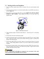
8.3
Valve Block Mounting
Ensure no hydraulic components will interfere with any sprayer parts or be pulled
tight at any time.
1. Mount the valve block on the sprayer near the existing valve block.
2. Use the supplied valve bracket B10 to install the valve block.
3. Insert the threaded rod into the block and use a hex nut to hold the rod. The block holes
are 3/8” NC-1” deep. If bolts are used instead of the threaded rod, ensure the bolts thread
in at least 3/8”.
4. Use the remaining hardware to secure the block to the sprayer.
5. Cut off excess threaded rod, if necessary.
Figure 30: Valve Block Mounting
27
8.4
Hydraulic Plumbing: Electrically Teed Installation
From this point on in the installation the booms will be inoperative until the
hydraulics are fully installed.
1. After the NORAC valve is mounted, the hydraulic hoses and fittings can be plumbed. The
plumbing for the hydraulic circuit is shown schematically in Figure 5.
2. Disconnect the pressure and tank lines from the sprayer valve block and insert the two tees
(*F01) between the hoses and the valve block.
3. Connect two hydraulic hoses (*H01) from the free ends of the tees to the pressure and
tank port on the NORAC valve block.
4. Disconnect the existing boom tilt cylinder “raise” hoses from the sprayer valve block. Plug
the ports on the sprayer valve block (*F02). Connect the boom tilt cylinder hoses to the
ports on the NORAC valve block. The “raise” lines must be connected to the “B” ports.
5. If the sprayer is dual acting, disconnect the existing boom tilt cylinder “lower” hoses from
the sprayer valve block. Plug the ports on the sprayer valve block (*F02). Connect the
boom tilt cylinder hoses to the ports on the NORAC valve block. The “lower” lines must
be connected to the “B” ports.
6. If the sprayer is single acting, the “lower” lines remain connected to the sprayer valve block
and the “A” ports on the NORAC block are plugged (F08).
28
8.5
Hydraulic Plumbing: Hydraulically Teed Installation
From this point on in the installation the booms will be inoperative until the
hydraulics are fully installed.
1. After the NORAC valve is mounted, the hydraulic hoses and fittings can be plumbed. The
plumbing for the hydraulic circuit is shown schematically in Figure 7.
2. Disconnect the pressure and tank lines from the sprayer valve block and insert the two tees
(*F01) between the hoses and the valve block.
3. Connect two hydraulic hoses (*H01) from the free ends of the tees to the pressure and
tank port on the NORAC valve block.
4. Disconnect the existing “raise” lines from the sprayer valve block. Install a tee fitting (*F01)
onto the valve block port. Connect the “raise” lines and hoses (*H04) to the tee. Connect
hoses (*H04) to the “B” ports of the NORAC valve block.
5. If the sprayer is double acting, disconnect the existing “lower” lines from the sprayer valve
block. Install a tee fitting (*F01) onto the valve block port. Connect the “lower” lines and
hoses (*H04) to the tee. Connect hoses (*H04) to the “A” ports of the NORAC valve
block.
6. If the sprayer is single acting, the “lower” lines remain connected to the sprayer valve block
and the “A” ports on the NORAC block are plugged (F08).
29
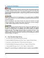
9
Software Setup
1. Start up the sprayer and test the sprayer’s functionality. The control panel does not need
to be powered on for the original boom function switches to operate. Unfold the booms
and raise/lower each boom and the main section.
Confirm that the cabling and hoses are agreeable to the entire range of motion.
2. If any functions do not work, review the hydraulic and electrical portions of this manual to
check for proper installation.
3. Turn on the power for the UC4.5 Control Panel using the switch on the side of its chassis.
4. Begin the AUTOMATIC SYSTEM SETUP procedure as described in the UC4.5 Spray
Height Control Operator’s Manual (M01).
Performance may be limited during the Control System Test in the
Automatic Setup since the slant valve has not been calibrated yet. It is
recommended to repeat the control system test again after the slant valve
has been calibrated.
5. After the AUTOMATIC SYSTEM SETUP, manually calibrate the slant valve as described in
Section 10.
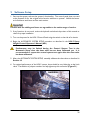
6. For optimal performance of the UC4.5 system, there should be very little play at the hitch
clevis. The addition of polymer washers can help tighten up this connection (Figure 31).
Figure 31: Hitch Point
30
10 Calibrating the Slant Valve
There are two key settings for each valve direction. These settings are valve DeadZone, "DZ",
and valve GAIN, "KP".
The DeadZone ("DZ") setting represents the size of electrical signal required at the solenoid
valve to cause a boom speed of one inch per second (Section 10.1).
The GAIN ("KP") setting is inversely related to the maximum speed of the boom. That is, the
faster the boom the lower the GAIN setting (Section 10.2).
IMPORTANT:
Before setting up the slant valve, ensure the following steps are complete.
1. Unfold the sprayer in a location that is relatively level, and where the sensors are over bare
soil or gravel. Do not conduct the setup procedure over standing crop, or tall weeds/grass.
2. Check the pads between the sprayer boom and the boom carrier frame to ensure no
friction because of wear. Use grease or other lubricants, if necessary. This is important and
will increase the UC4.5 Spray Height Control system performance significantly.
3. Start the solution pump and run the sprayer’s engine at a normal working RPM for the
entire setup. Make sure that the height of all the booms can be manually adjusted. For best
results, the hydraulic system should be under a normal load and at a normal working
temperature. An effective way to warm the oil is to cycle all boom sections up and down
manually for 5 minutes. Longer warm up times may be required in cold weather. For pulltype sprayers, ensure any hydraulic flow controls are adjusted for normal field operation.
Changing the flow controls during or after the setup will affect the UC4.5 operation.
Table 4: Roll Channel SETUP Menus
Navigating past the end of the menu will return the panel to the Setup…”More”
switches.
Menu. Readings are adjusted using the
Roll OnU
Informs the user that the roll valve channel is ON. To change the status to OFF,
switches.
use the
DZ 20
Informs the user that the roll CW (clockwise) DeadZone setting is 20.
KP 10
Informs the user that the roll CW GAIN setting is 10.
DZ 20
Informs the user that the roll CCW (counter clockwise) DeadZone setting is 20.
KP 10
Informs the user that the roll CCW GAIN setting is 10.
Navigating past the end of the menu will return the panel to the Setup…”More”
Menu
31
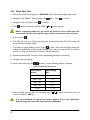
10.1 Valve DeadZone Test
1. Ensure the UC4.5 control panel is in MANUAL mode at the Normal Operating Screen.
2. Navigate to the "More ?" menu prompt in the
3. Navigate to the roll section. Press
menu. Press
to confirm.
to confirm.
4. Press
switch to access the next menu prompt, in this case the roll cw DeadZone
(" DZ "). Press and hold
.
5. The valve will turn on at the indicated setting for a short amount of time based on the value
of the DZ setting. A larger setting will turn the valve on for a longer period of time. The
LCD screen will show the actual change in height.
Ensure the boom moves in the clockwise direction (left boom up, right boom
down). If the boom moves in the opposite direction, check the wiring and/or
hydraulics for an installation error.
6. The change in height reading is live as long as
settled to a stable value and record this reading.
is held. Wait until the height reading has
Some sprayers may exhibit unwanted movement in the boom due to
mechanical play. This may cause some of the tests to show no movement at
all if the mechanics of the boom are loose. It is recommended to take at
least five readings to ensure the tests are accurate.
7. Average the five readings. The acceptable average change in height should be from 13 to 38
mm (0.5 to 1.5 inches) (ideal would be 25 mm (1 inch) exactly).
8. If the average is less, increase the DZ setting with using
.
decrease the DZ setting using
. If the average is more,
9. Repeat the Dead Zone Test until the average falls into the acceptable range.
10. When satisfied with the DeadZone roll clockwise test (" DZ "), repeat this test for the
roll counter clockwise (" DZ ").
32
10.2 Valve Gain Test
1. Ensure the UC4.5 control panel is in MANUAL mode at the Normal Operating Screen.
2. Navigate to the "More ?" menu prompt in the
to confirm.
to confirm.
3. Navigate to the roll section. Press
4. Press
menu. Press
twice to access the roll CW GAIN (" KP ") menu prompt.
Before continuing make sure the boom has room to move at full speed for
one second. Ensure the main lift is up to allow room for the boom to move.
5. Press and hold
.
6. The valve will turn on at 100 percent speed for exactly one-second. The LCD screen will
show the actual change in height.
7. The change in height reading is live as long as
is held. Wait until the height reading has
settled to a stable value and record this reading. This is the boom speed in mm per second
(mm/s) or inches per second (in/s) if inches is the selected units.
8. Repeat the Manual Gain Test three times, repositioning the boom as necessary.
9. Average the three readings
10. Set the Gain value using the
buttons. Use the following table as a guideline.
Table 5: Roll Section Parameters
Boom Speed
(mm/s)
Gain Setting
(KP)
> 2200
1
2200 - 1000
1-5
1000 - 400
5-9
400 - 100
9 - 11
< 100
11 - 12
11. When satisfied with the Gain roll clockwise test (" KP "), repeat this test for the roll
counter clockwise (" KP ").
It is recommended to repeat the Control System Test in the Automatic
System Setup after the slant valve has been calibrated.
33
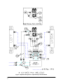
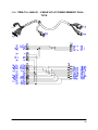
11 Cable Drawings
11.1 ITEM C03: 44656D – CABLE VALVE VARIABLE RATE DT
34
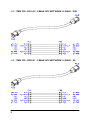
11.2 ITEM C05: 43210-20 - CABLE UC5 NETWORK 18 AWG - 20M
11.3 ITEM C07: 43220-01 - CABLE UC5 NETWORK 14 AWG - 1M
35
11.4 ITEM C10: 44650-51 - CABLE UC4.5 POWER GENERIC PULLTYPE
36
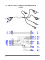
11.5 ITEM C11: 44651-50 - CABLE UC4.5 EXTENSION VALVE
GENERIC
37
11.6
ITEM C30: 43250-06 – CABLE UC5 BATTERY PIGTAIL
FUSED - 5A
38
Canada
NORAC Systems International Inc.
Phone: (+1) 306 664 6711
Toll Free: 1 800 667 3921
Shipping Address:
3702 Kinnear Place
Saskatoon, SK
S7P 0A6
United States
NORAC, Inc.
Phone: (+1) 952 224 4142
Toll Free: 1 866 306 6722
Shipping Address:
6667 West Old Shakopee Road, Suite 111
Bloomington, MN
55438
Europe
NORAC Europe sarl
Phone: (+33) 04 26 47 04 42
Shipping Address:
Rue de l’hermitage
01090 Guereins
France
www.norac.ca