1
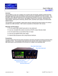
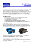
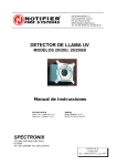
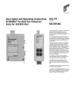
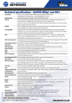
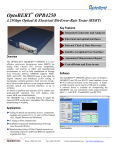
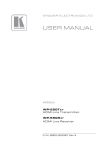
Eye-BERT Micro Family Users Manual Overview: The Eye-BERT Micro Family of products provide low cost, easy to use, electrical and optical test solutions offering high performance bit error rate testing at a fraction of the cost while providing a rich set of features not found in other bit error rate testers. Features include: variable bit rate, user programmable patterns, optical power and temperature monitoring, and transceiver register read / write capability. Some models offer single click transceiver testing which automatically tests the pluggable transceiver based on the information it reads from the module and generates a detailed test report complete with manufacturer, part number, serial number, date code, fiber type, link length, speed, and test results. The Units are supplied with anti-skid bumpers for bench use and are small enough to be integrated into larger systems for dedicated link verification. A summary of the models is listed below: Model Rates Interfaces Eye-BERT Micro LR (100357A-XXX) 6.312 Mbps – 125Mpbs (continuous) Electrical SMA, 1310nm, 1550nm Eye-BERT Micro (100286A) 125Mbps – 4.25Gbps (banded) Pluggable: any MSA compliant SFP Eye-BERT Micro 10G (100292A) 9.95Gbps – 11.3Gbps (continuous) Pluggable: Any MSA compliant XFP Warnings and Precautions: Do not exceed manufacturers recommended optical input power on any port Use only compatible fiber optical connectors and modules Use only the supplied 5VDC power supply as applicable Observe ESD precautions when handling Proper ventilation or heat sinking may be required depending on the environment and transceiver Installing the Software and Starting the Application Regardless of the model, all Eye-BERT Micro’s use the same easy to operate software application and USB driver. 1. Insert the CD or download the application from www.spectronixinc.com, run the “Eye-BERT Micro Install.exe” installation program. 2. Connect power to the Eye-BERT Micro using the supplied 5VDC adapter (select models). 3. Plug the Eye-BERT Micro into a free USB port. When the hardware installation wizard asks for the driver location, browse to “cdc_NTXPV764.inf” located in the installation directory. Note, on some operating systems such as Window 7, manual USB driver installation may be necessary. If the hardware installation wizard fails, go to “My Computer” > “Properties” > “Hardware” > “Device Manager”, and find the “Spectronix” or “SERIAL DEMO” entry under www.spectronixinc.com Page 1 Eye-BERT Micro Family User’s Guide V 2.0 “Other Devices” and select “Update Driver”. At this point you will be able to browse to the location of the driver. 4. Start the application from the program start menu Using the Supplied Eye-BERT Micro Application At start-up the Eye-BERT Micro Application searches for compatible Eye-BERT Micro devices and lists them in the “Port” drop down box. The Eye-BERT must be powered on and connected to a USB port prior to launching the Eye-BERT Micro Application. Once the user selects a device from the list, the connection LED will turn green and the fields will begin to update. The Eye-BERT Micro can operate in either “Bit Error Rate Test” mode or “Repeater” mode. In repeater mode the input signal is retimed and retransmitted, this is useful for clock recovery and jitter clean-up. In bit error rate test mode the Eye-BERT Micro generates the specified pattern / bit rate while the detector attempts to synchronize to the pattern and count the bit errors. Note, some special test patterns are intended for jitter testing and are not supported by the pattern detector, see the specific model notes for details. Testing with the Eye-BERT Micro Generating a Test Pattern: The rate knob is used to set the bit rate at which the Eye-BERT Micro operates at; rate options will vary depending on which model is chosen. When the “Standard Rates Only” box is selected the dial will jump between standard data rates only. When this box is not checked the user will be allowed to select any data rate using the dial. The user can also change the data rate by entering a rate directly into the dialog box and pressing <enter>. The pattern slider bar is used to change the output test pattern or select repeater / retimer mode; pattern capability varies by model type. All PRBS patterns, K28.5, and DCD patterns are supported by the pattern detector and can be used for bit error testing. The CJTPAT, CRPAT, and CSPAT patterns are intended only for jitter testing and are not supported by the pattern detector. The repeat mode simply retimes and retransmits the input signal and is not supported by the pattern detector. The operation of the “Custom” pattern varies by model: • Eye-BERT Micro LR (pulse generator): generates a pulse stream with a pulse repetition rate as selected by the “Rate” setting / 100 and a duty cycle per the duty cycle dialog box 1-99%. For example, using a rate of 100Mbps and a duty cycle of 1% gives a 10nS pulse every 1uS. This function is not supported by the pattern detector. www.spectronixinc.com Page 2 Eye-BERT Micro Family User’s Guide V 2.0 • Eye-BERT Micro (40 bit custom pattern): generates a repeating 40 bit custom pattern as dictated by the 10 character hex pattern in the dialog box. This is supported by the pattern detector and can be used for bit error rate testing. • Eye-BERT Micro 10G (64 bit custom pattern): generates a repeating 64 bit custom pattern as dictated by the 16 character hex pattern in the dialog box. This is supported by the pattern detector and can be used for bit error rate testing. Controlling the Transmitter The transmitter output signal can be enabled or disabled on any model by pressing the “Tx” button; the LED indicates the state of the transmitter. On models with a pluggable transceiver, the optical output power is also displayed on the “Tx” button. Transmitter Wavelength On models that use pluggable transceivers, the transmitter wavelength is indicted on the button. If a tunable XFP module is used, the output wavelength can be changed. Pressing the wavelength button opens the “Set Wavelength” dialog box. The current wavelength (nm) and frequency (THz) is displayed at the bottom of the window for reference. Adjusting either the frequency or wavelength dial will change the other dial to the corresponding value to the nearest 50GHz channel. Press <OK> to set the new wavelength. Receiver Measurements Signal and Sync LEDs along with the receiver measurements are provided to give the user an indication of the received signal quality. The signal LED turns green when the AC signal amplitude is above the minimum level for reliable operation. The Sync LED turns green when the receiver CDR / pattern detector has locked onto the signal. The receiver measurement indicates either the received optical power (pluggable transceiver models) or the received bit rate. www.spectronixinc.com Page 3 Eye-BERT Micro Family User’s Guide V 2.0 Bit Error Rate Measurements The “BERT” section reports the number of bit errors, the total number of bits tested, the bit error rate (errors / bits tested), and the test time in days, hours, minutes, seconds. The LED next to the bit error rate is red if the rate is not zero and the LED next to the error counter flashes red when an error is received. The “Reset” button is used to reset all counters to zero. Transceiver Utilities In units with pluggable transceivers, the “Utilities” button will be displayed. Selecting this button will display the transceiver utilities window. From this window the user can read and write the registers and test the transceiver. Pressing the “Read” button will read and display all the transceiver registers as shown below. The transceiver can be tested by connecting a loopback cable and attenuator. With APD receivers, be sure to use enough attenuation to prevent damage or saturation of the receiver. Press “Test” to begin the transceiver test. After about 20 seconds the results will appear in the window. Individual registers can be read or written to using the “Rd” and “Wr” buttons along with the address and value dialog boxes. In the example below, entering 00 (hex) in the address button and pressing “Rd” displays the value of register 00 = 06 (hex). The value of a register can be changed by entering the address and data and pressing the “Wr” button (all values are hex). Please note that not all registers are writable, refer SFF-8472 for more information. Data Logging Data can be logged to an Excel compatible CSV file in one second intervals by pressing the “Log” button. During logging, the log LED will flash green/yellow to indicate logging is in process. Press the log button again to stop logging. An example log file is shown below. Eye-BERT Micro 10G Log file Mon Dec 17 2012 Time Rate Pattern Temp (C) Rx (dBm) Count Errors BER 14:47:34 1.13E+10 PRBS31 50.9 -8.9 3.64E+13 5.36E+02 1.47E-11 14:47:35 1.13E+10 PRBS31 50 -8.9 3.64E+13 5.36E+02 1.47E-11 14:47:36 1.13E+10 PRBS31 50 -8.9 3.64E+13 5.36E+02 1.47E-11 14:47:37 1.13E+10 PRBS31 50 -8.9 3.64E+13 5.36E+02 1.47E-11 www.spectronixinc.com Page 4 Eye-BERT Micro Family User’s Guide V 2.0 Thermal / Power Considerations The Eye-BERT Micro enclosure provides a low thermal resistance path from the internal electronics and the transceiver module to the extruded aluminum housing, therefore some minimal air circulation or heat sinking is recommended. The unit is designed to be used in an open “laboratory type” environment (such as on a bench) with some amount of air circulation or attached to a thermal sink using the flanges. If the unit is to be utilized at elevated temperatures or mounted in a stagnant environment where heat build up might occur, it is recommended that additional thermal management be employed such as using fans or additional heat sinking and thermal gasket material. When using a transceiver which supports digital diagnostics, the temperature may be monitored from the software user interface. Note, most commercial grade SFP/XFP modules are rated for an ambient temperature of at least 70°C. When the Eye-BERT Micro is connected to an active (powered) USB port, the unit is on and generating heat whether or not the application is running. In order to turn off the unit either remove power or unplug / deactivate the USB connection. The unit will power down when the connected computer powers down, providing that the computer removes power from the USB cable. This allows the unit to remain connected to a system and powered on / off with the controlling computer. Mechanical Dimensions 3.50” 1.20” 1.43” 0.220” Slot width 3.66” 3.20” (mounting centers) 3.80” (overall) 2.75” www.spectronixinc.com Page 5 Eye-BERT Micro Family User’s Guide V 2.0 APPENDIX LETTER OF VOLOTILITY All products in the Eye-BERT Micro family contain both volatile and non volatile memory. Only the Eye-BERT Micro firmware application is stored in non volatile memory and program variables and settings are stored in volatile RAM which is cleared upon power down. The user has no means of altering the non volatile memory without opening up the unit and reprogramming the device using a special programming adapter. www.spectronixinc.com Page 6 Eye-BERT Micro Family User’s Guide V 2.0