1
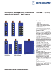
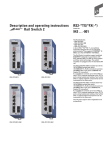
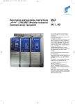
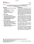
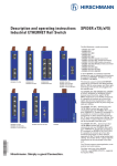
Description and Operating Instructions
ETHERNET Twisted Pair Industrial
Hubs for ISO/DIN Rail
RH1-TP
Order No.
943 639-001
The rail hub RH1-TP supports a fast and reasonable network expansion. You can
connect up to four data terminal equipments or further twisted pair segments via
twisted pair.
For startup procedure just fit the rail hub
on an ISO/DIN rail, without any further configuration time. The V.24 voltage is supplied
via the terminal block and can be feed in
redundantly.
RH1-TP
P1
P2
1
2
3
4
DA/STAT
DIL Switch Settings:
Port 1 … Port 4
LA1 … LA4
Link Alarm
0
1
Disabled
Enabled
Port 1
Made in Germany
Port 2
C
Port 3
Port 4
The terminal block contains an integrated
indicator contact, receiving error and warning messages of the rail hub which are
defined as digital signals. These signals e.g.
can be utilized as process messages by a
programmable logic control (PLC). The indicator contact becomes active as soon as
disturbances appear in the rail hubs, that is
when a power supply should fail or at least
one TP port reports a faulty link status or
has auto partitioned.
For diagnosis there are LEDs available
which indicate collisions, link status, segmentation, power and received data.
The railhub has four twisted pair (TP)
interfaces. It is possible to connect up to
four terminals or other TP segments using
TPs.
The module conforms to the specifications
of ISO/IEC standard 8802-3.
You will find a detailed description for construction of a local area network on network
planning and installation in the “Ethernet
manual“ (Order no. 943 320-011).
We have checked that the contents of the
technical publication agree with the hardware and software described. However, it is
not possible to rule out deviations completely, so we are unable to guarantee complete agreement. However, the details in the
technical publication are checked regularly.
Any corrections which prove necessary are
contained in subsequent editions. We are
grateful for suggestions for improvement.
We reserve the right to make technical
modifications.
Permission is not given for the circulation
or reproduction of this document, its use or
the passing on of its contents unless granted expressly. Contravention renders the
perpetrator liable for compensation for
damages. All rights reserved, in particular
in the case of patent grant or registration of
a utility or design.
z
z
Safety Instructions
This manual contains instructions which
must be observed to ensure your own personal safety and to avoid
damage to devices and machinery. The
instructions are highlighted with a warning
triangle and are shown as
follows according to the degree of endangerment:
z
2
Danger!
means that death, serious injury or
considerable damage to property
will result if the appropriate safety
measures are not taken.
Safety Guidelines
Shielding Ground
Note: The shielding ground of the connectable twisted pairs lines is connectedto the
front panel as a conductor.
Beware of possible short circuits when
connecting a cable section with conductive
shielding braiding.
Safety Guidelines Housing
z
Certified usage
Please observe the following:
z
Note
We would furthermore point out that for
reasons of simplicity, these operating
instructions cannot describe every
conceivable problem associated with the
use of this equipment. Should you require
further information or should particular
problems occur which are not treated in
sufficient detail in the operating instructions, you can request the necessary information from your local Hirschmann sales
partner or directly from the Hirschmann
office (address: refer to chapter entitled
„Notes on CE identification“).
Caution!
means that light injury or damage to
property can result if the appropriate safety measures are not taken.
Note: is an important piece of information
about the product, how to use the product,
or the relevant section of the documentation to which particular attention is to be
drawn.
Copyright
© Hirschmann Electronics GmbH & Co. KG 2000
All Rights Reserved
We would point out that the content of
these operating instructions is not part of,
nor is it intended to amend an earlier or existing agreement, permit or legal relationship. All obligations on Hirschmann arise
from the respective purchasing agreement
which also contains the full warranty conditions which have sole applicability. These
contractual warranty conditions are neither
extended nor restricted by comments in
these operating instructions.
Warning!
means that death, serious injury or
considerable damage to property
can result if the appropriate safety
measures are not taken.
Warning
The device may only be employed
for the purposes described in the
catalog and technical description,
and only in conjunction with external
devices and components recommended or approved by Hirschmann.
The product can only be operated
correctly and safely if it is transported, stored, installed and assembled
properly and correctly. Furthermore,
it must be operated and serviced
carefully.
Safety Guidelines
Power Supply
Switch the basic devices on only when
the case is closed.
z
Warning!
The devices may only be connected
to the supply voltage shown onthe
type plate.
The devices are designed for operation with a safety extra-low voltage.Thus, they may only be connected to the supply voltage connections and to the signal contact with
the safety extra-low voltages (SELV)
in compliance with IEC950/
EN60950/ VDE0805.
For the case where the module is operated with external power supply: Use only a
safety extra-low voltage in accordance with
IEC 950/EN 60 950/VDE 0805 to power the
system.
First of all you connect the protecting
line, before you estabilsh the further
connections. When you remove connections, you disconnect the protecting line
last.
Warning!
Only technicians authorized by Hirschmann are permitted to open the
housing.
Make sure that the electrical installation
meets local or nationally applicable safety
regulations.
z
Warning!
The ventilation slits must not be
covered so as to ensure free air circulation.
The distance to the ventilation slots
of the housing has to be a minimum
of 10 cm.
Never insert pointed objects (thin
screwdrivers, wires, etc.) into the
inside of the subrack! This especially applies to the area behind the
socket connectors. Failure to observe this point may result in injuries
caused by electric shocks.
Note: According to EN 60950 the device
may only be operated in a fire protective
housing.
Note: The housing has to be mounted in
upright position.
Safety Guidelines Environment
z
Warning!
The device may only be operated in
the listed ambient temperature
range at the listed relative air humidity (non-condensing).
The installation location is to be selected so as to ensure compliance with the climatic limits listed in the Technical Data.
Staff qualification
requirements
Note: Qualified personnel, as understood
in this manual and in the warning signs, are
persons who are familiar with the setup,
assembly, startup, and operation of this
product and are appropriately qualified for
their job. This includes, for example, those
persons who have been:
– trained or directed or authorized to
switch on and off, to ground and to label
power circuits and devices or systems in
accordance with current safety engineering
standards
– trained or directed in the care and use of
appropriate safety equipment in accordance with the current standards of safety
engineering
– trained in providing first aid.
General Safety Instructions
This device is electrically operated.
Adhere strictly to the safety requirements
relating to voltages applied to the device as
described in the operating instructions!
z
Warning!
Failure to observe the information
given in the warnings could result in
serious injury and/or major damage.
Only personnel that have received
appropriate training should operate
this device or work in its immediate
vicinity. The personnel must be fully
familiar with all of the warnings and
maintenance measures in these
operating instructions.
Notes on CE identification
The devices comply with the regulations of the following European
directive:
89/336/EEC
Council Directive on the harmonisation of the legal regulations of
member states on electromagnetic
compatibility (amended by Directives 91/263/EEC, 92/31/EEC and
93/68/EEC).
Note:
0 FCC
This equipment has been tested and
found to comply with the limits for a
Class A digital device, persuant to
part 15 of the FCC Rules. These
limits are designed to prvide reasonable protection against harmful
interference when the equipment is
operated in a commercial environment. This equipment generates,
uses, and can radiate radio frequency energy and, if not installed and
1. Functional description
1.1 GENERAL FUNCTIONS
Signal regeneration
The RH1-TP processes the signal shape and
amplitude of the data received.
Retiming
In order to prevent jitter increasing over
several segments, the RH1-TP retimes the
data to be transmitted.
Area used
Industrial
Correct transport, storage, and
assembly as well as careful operation and maintenance are essential in
ensuring safe and reliable operation
of this device.
These products are only to be used in
the manner indicated in this version of the
”Description and Operating Instructions”.
Particular attention is to be paid to all
warnings and items of information relating
to safety.
z
Warning!
Any work that may have to be performed on the electrical installation
should be performed by fully qualified technicians only.
Requirements for
emitted interference
interference immunity
EN 50081-2: 1993
EN 50082-2: 1995
EN 55022 Class A: 1998
The EU declaration of conformity is kept
available for the responsible authorities in
accordance with the above-mentioned EU
directives at:
Hirschmann Electronics GmbH & Co. KG
Automation and Network Solutions
Stuttgarter Straße 45-51
D-72654 Neckartenzlingen
Telephone ++49-7127-14-1538
used in accordance with the instruction manual, may cause harmful
interference to radia communications. Operation of this equipment in
a residential area is likely to cause
harmful interference in which case
the user will be required to correct
the interference at his own expense.
Preamble regeneration
The RH1-TP supplements lost preamble bits
from data received to 64 bits (incl. the start
of frame delimiter (SFD)).
Fragment extension
Collisions can cause short fragments to
occur. If the RH1-TP receives a fragment,
this is supplemented to give the minimum
length of 96 bits. This ensures reliable collision detection by all network participants.
The product can be used in the residential sphere (residential sphere, business
and trade sphere and small companies)
and in the industrial sphere.
The precondition for compliance with
EMC limit values is strict adherence to
the construction guidelines specified in
this description and operating
instructions.
,
Recycling Note:
After its use, this product has to be
processed as electronique scrap to a
proper disposal according to the prevailing waste disposal regulations of
your community / district / country /
state.
Collision handling
If the RH1-TP detects a data collision, it
interrupts the transmission. For the
duration of the collision, the collided data
package is replaced by a jam signal to
ensure collision detection by the terminal
equipments.
Auto partitioning
Network failures can be caused by permanent occupancy, interruptured lines, lack of
terminating resistors, damaged cable insulation and frequent collisions due to electromagnetic interference. In order to protect
3
the network from such failures, the RH1-TP
in this case separates the segment in the
receiving direction from the rest of the network.
The RH1-TP has this auto partitioning function individually at each port. The other
ports can thus continue to be operated
without interference if one of the ports has
been auto partitioned. In the event of auto
partitioning, transmission continues into
the TP segment but reception at this port is
blocked.
With twisted pair, auto partitioning is activated if
– a data collision lasts longer than 105 µs or
– there are more than 64 consecutive data
collisions.
Reconnection
The segment is reconnected to the network
as soon as a package with the minimum
length of 51 µs is received without collision
at the relevant port, i. e. when the segment
is working properly again.
Jabber control
Due to a defective transceiver or LAN controller, for example, the network can be continuously occupied with data. To protect
against this, the RH1-TP interrupts reception
at the affected TP port after 5.5 ms for a
duration of 9.6 µs. This cycle (transmission
for 5,5 ms, interruption for 9,6 µs) is repeated until the end of the error (jabber lockup
protection).
1.2 SPECIFIC FUNCTIONS OF THE
TP INTERFACE
Link control
The RH1-TP monitors the connected TP line
segments for short-circuit or interrupt using
idle signals during frame pauses in accordance with IEEE standard 802.3 10BASE-T.
The RH1-TP does not transmit any data in a
TP segment from which it does not receive
an idle signals.
Note: A non-occupied interface is assessed
as a line interrupt. The TP line to terminal
equipment which is switched off is likewise
assessed as a line interrupt as the deenergised transceiver cannot transmit idle
signals.
Auto polarity exchange
If the reception line pair is incorrectly
connected (RD+ and RD- switched) polarity
is automatically reversed.
1.3 DISPLAY ELEMENTS
Equipment status
The two LEDs provide information about
the status which affects the function of the
entire RH1-TP.
P1 – Power 1 (green LED)
– lit: supply voltage 1 present
– lit not: – supply voltage 1 not present,
– hardware fault in RH1-TP
P2 – Power 2 (green LED)
– lit: supply voltage 2 present
– lit not: – supply voltage 2 not present,
– hardware fault in RH1-TP
5-pin terminal block
The supply voltage and the indicator
contact are connected via a 5-pin terminal
block with screw locking mechanism.
Port Status
These groups of LEDs display port-related
information.
DA/STAT 1 to DA/STAT 4 - link status
of the TP ports (4 x green/yellow LED)
– lit yellow: RH1-TP receiving data
– lit green: RH1-TP receiving link test pulses from TP segment,
– the TP segment connected is
working properly
– flashes
green:
port has auto partitioned
– lit not:
RH1-TP is not receiving any idle
signals from TP segment,
– the assigned TP port is not
connected,
– the equipment connected is
switched off,
– the TP line is interrupted or
short-circuited
z
1.4 CONTROLS
6-pin DIP switch
Using the 6-pin DIP switch on the top of the
RH1-TP housing
– the message about the link statuses can
be suppressed by the indicator contact on
a port-by-port basis. Using switches LA1
to LA4, the message about the link status
of ports 1 to 4 is suppressed. State on delivery: switch position 1 (ON), i.e. message
not suppressed.
Off On
LA1 Port 1
LA2 Port 2
LA3 Port 3
LA4 Port 4
not connected
not connected
Suppress message
about link status
via indicator contact
Fig. 1: 6-pin DIP switch
1.5 INTERFACES
TP connection
Four 8pole RJ45 sockets enable four independent TP segments to be connected.
– Pin configuraion of the RJ45 socket:
– TD+: Pin 3, TD-: Pin 6
– RD+: Pin 1, RD-: Pin 2
– remaining pins: not configured.
n.c.
n.c.
TDn.c.
n.c.
TD+
RDRD+
Pin 8
Pin 7
Pin 6
Pin 5
Pin 4
Pin 3
Pin 2
Pin 1
Fig. 2: Pin configuration TP interface
L1+
Warning!
The RH1-TP equipment is designed
for operation with SELV. Only safe
extra-low voltages to
IEC950/EN60950/VDE0805 may
therefore be connected to the
supply voltage connections and to
the indicator contact.
+24 V
F1
M
Fault
F2
L2+
+24 V *
Fig. 3: Pin configuration of 5-pin terminal
block
– Voltage supply: The voltage supply can
be connected to be redundant. Both
inputs are decoupled. There is no load
distribution. With redundant supply, the
power pack supplies the RH1-TP alone
with the higher output voltage. The
supply voltage is electrically isolated from
the housing.
– Indicator contact: Contact interrupt
indicates the following by means of a
potential-free indicator contact (relay
contact, closed circuit):
– the failure of at least one of the two
supply voltages.
– a permanent fault in the hub for ISO/DIN
rail (internal 5 V DC voltage, supply voltage 1 or 2 not in the permissible range).
– the faulty link status of at least one TP
port.
The indication of the link state might be
masked on a port-by-port basis using
DIP switches.
– at least one port has auto partitioned.
Note: In the case of the voltage supply
being routed without redundancy, the RH1TP indicates the failure of a supply voltage.
You can prevent this message by feeding in
the supply voltage through both inputs.
2. Configuration
automaton
2.1 STAND ALONE STRUCTURE
STAR SHAPED STRUCTURE
The RH1-TP enables connection of up to
four data terminal equipments or further
twisted pair segments via twisted pair.
2.2 EXPANSION OF EXISTING
NETWORKS
The rail hub RH1-TP gives you the possibility to expand your network in a fast and reasonable way, for example an existing rail
hub-/rail switch link.
Rail Hub
RH1-TP
twisted pair
line
DTE
twisted pair
transceiver
RH1TP/FL
RH1TP/FL
RH1TP/FL
RH1TP/FL
automaton
twisted pair
line
F/O line
Rail Hub link
with redundant line
RH1-TP
twisted pair
line
Fig. 5: Expansion of a rail hub link
Rail Switch RS1-TP
DTE
transceiver
PLC
automaton
Fig. 4: Stand-alone configuration of the
RH1-TP
twisted pair
100 m
Rail Hub
RH1-TP
Rail Hub
RH1-TP
Rail Hub
RH1-TP
DTE
transceiver
Fig. 6: Configuration with rail switch
3. Assembly, startup procedure
and dismantling
the bottom of the module onto the ISO/ DIN
rail until it locks in position (Fig. 7).
– Fit the signal lines.
3.1 UNPACKING, CHECKING
– Check whether the package was delivered
complete (see scope of delivery).
– Check the individual parts for transport
damage.
Notes:
– The housing of the RH1-TP is grounded
via the ISO/DIN rail. There is no separate
ground connection.
z
Warning!
Use only undamaged parts!
3.2 ASSEMBLY
The equipment is delivered in a ready-tooperate condition. The following procedure
is appropriate for assembly:
– Check whether the switch pre-setting suits
your requirements.
– Pull the terminal block off the RH1-TP and
wire up the supply voltage and indicator
lines.
– Fit the RH1-TP on a 35 mm ISO/DIN rail to
DIN EN 50 022.
– Suspend the upper snap-in hook of the
RH1-TP in the ISO/DIN rail, insert a
screwdriver horizontally under the housing into the locking slide pull this downwards (cf. Fig. 8, dismantling) and press
– The screws in the lateral half-shells of the
housing may not be undone under any
circumstances.
– The shielding ground of the twisted pair
lines which can be connected is electrically connected to the housing.
3.3 STARTUP PROCEDURE
You start up the RH1-TP by connecting the
supply voltage via the 5-pin terminal block.
Lock the terminal block with the locking
screw at the side.
3.4 DISMANTLING
To take the RH1-TP off the ISO/DIN rail, insert a screwdriver horizontally under the
housing into the locking slide, pull it (without tipping the screwdriver) downwards
and fold the RH1-TP upwards.
RH1-TP
P1
P2
1
2
3
4
DA/STAT
Port 1
Port 2
Port 3
Port 4
Locking slide
Fig. 8: Dismantling the RH1-TP
Fig. 7: Assembling the RH1-TP
5
4. Further support
In the event of technical queries, please talk
to your local Hirschmann sales partner or
directly to the Hirschmann agency in your
country. You can find the addresses
– on the Internet
(http://www.hirschmann.de)
and our US support office
Tel. +800-225-0524
are also at your disposal.
Our hotline in Germany
Tel: +49-7127-14-1538 (Fax: -1542)
5. Technical data
General data
Operating voltage
Buffer time
9.6 to 32 VDC safe extra-low voltage (SELV) (redundant inputs decoupled)
min. 10 ms at 24 VDC
Potential difference between input
voltage and housing
Potential difference to input voltage, +24 VDC: 32 VDC
Potential difference to input voltage, ground: -32 VDC
Requirements to the protecting line
Current consumption
30 A for 2 minutes
typ. 80 mA at 24 VDC (without data)
max. 130 mA at 24 VDC (with data)
Overload current protection at input
Dimensions W x H x D
Mass
Ambient temperature
Storage temperature
Humidity
Air pressure
Protection class
Radio interference level
Interference immunity
non-changeable thermal fuse
40 mm x 125 mm x 80 mm
530 g
0 ºC to + 60 ºC
- 40 ºC to + 80 ºC
10% to 90% (non condensing)
min. 70 kPa
IP 30
EN 55022 Class B
EN 50082-2
Interfaces
4 ports in compliance to 10BASE-T with RJ45 connectors (shielded)
1 x 5 pole mountable terminal block
Displays
P1, P2: power
DA/STAT 1 to DA/STAT 4: data, collision, link status per port, segmentation
(1.57 in x 4.92 in x 3.15 in)
(1.167 lb)
(32 ºF to + 140 ºF)
(-40 ºF to + 176 ºF)
Network size
Transition
Propagation equivalent
Variability value
TP line length (TP-Port ↔ TP-Port)
Length of a twisted pair segment
TP-Port ↔ TP-Port
190 m
(624 ft)
4 BT
max. 100 m
(328 ft)
Scope of delivery
RH1-TP Twisted Pair Industrial Hub for ISO/DIN Rail incl.
terminal block for supply voltage
description and operating instructions
Order number
RH1-TP – Twisted Pair Industrial Hub
for ISO/DIN Rail
943 639-001
Accessories
Ethernet manual
Rail Power Supply RPS 60
Rail Power Supply RPS 120
943 320-011
943 662-001
943 662-011
Hirschmann Electronics GmbH & Co. KG
Automation and Network Solutions
Stuttgarter Straße 45-51
D-72654 Neckartenzlingen
Germany
Tel.: ++49 / 7127 / 14-1538
Fax: ++49 / 7127 / 14-1542
E-Mail: [email protected]
Internet: http://www.hirschmann.com
Printed in Germany
Subject to alterations
039597001040201000