1
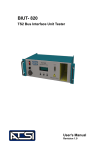
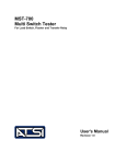
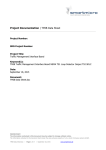
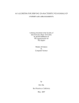
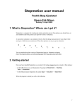
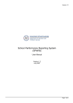
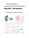
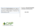
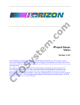
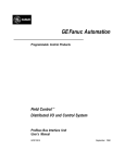
User's Manual
Revision 1.0
Contacting ATSI :
ATSI
8157 US Route 50
Athens, OH 45701
740-592-2874
Fax : 740-594-2875
www.atsi-tester.com
Email for purchasing information :
[email protected]
Email for service :
[email protected]
Table of Contents
Explanation of Symbols and Terms ........................
2
Safety Information .................................................
3
Installation ...............................................................
4-8
Operation ................................................................
9 - 10
Electrical and Mechanical Specifications ................
11
Service and Calibration ...........................................
12
Limited Warranty and Return Merchandise .............
13
1
TS2
Frame Grabber User's Manual Rev. 1.0
Explanation of Symbols and Terms
`
The following is a list of symbols and important terms that are
used throughout this manual. It is assumed that the reader is
familiar with the operation of a NEMA TS2 Type Traffic Control
System and has qualifications as described in the Safety
Information section of this manual.
Caution. Risk of danger. This symbol indicates
important information that must be read and
understood before attempting to install or use
the TS2 Frame Grabber.
Frame
A predefined format for the messages that are
exchanged using the SDLC protocol. The
NEMA TS2 Standard defines command frames
(sent by the controller) and responses frames
(sent by BIUs and conflict monitors).
FrameView
A PC software application for viewing, sorting,
and analyzing frame data.
NEMA
National Electrical Manufacturers Association.
PC
Personal computer
SDLC
Synchronous Data Link Communication
Protocol. Serial communication protocol by
which the controller, BIUs, and conflict monitor
exchange information in a TS2 type traffic
control system.
TS 2
Traffic Control Systems Standard published by
NEMA (see NEMA).
2
TS2
Frame Grabber User's Manual Rev. 1.0
Safety Information
IMPORTANT SAFETY INFORMATION !
READ BEFORE ATTEMPTING TO INSTALL THE
TS2
Frame Grabber
The TS2 Frame Grabber should only be installed by qualified and
authorized traffic signal technicians who are familiar with
generally accepted electrical safety practices, local and national
safety codes, the NEMA Standards Publication TS2-2003, and
any other relevant codes which may apply to the local traffic
signal installation.
3
TS2
Frame Grabber User's Manual Rev. 1.0
Installation
Installing the TS2 Frame Grabber in a signal cabinet is quick and
simple - normally requiring less than five minutes. The only
required connections are DC power and an SDLC cable.
DC Power Connection
The DC power connection is made with the supplied M8
threaded female molded cable. The threaded end connects to
the connector labeled "24 VDC" on the front of the Frame
Grabber. The other end of the cable has three leads colored
black, blue, and brown. The leads should be connected as
follows :
Blue : Connect to the cabinet Logic Ground.
Brown : Connect to the cabinet +24VDC supply.
Black : Not connected.
SDLC Cable Connection
There are two possible methods to make the connection to the
SDLC bus. The simplest method is to have a dedicated
communication cable. If a dedicated cable is not available, the
pass through method may be used. The two methods are
described on the following pages.
Dedicated Communication Cable
If the cabinet has an available SDLC communication cable (as
described in section 5.3.3 of the TS 2-2003 v02.06 Standard ),
simply plug the male DB15 connector into one of the mating
female DB15 connectors on the front of the Frame Grabber.
This is shown in the drawing on the following page.
4
TS2
Frame Grabber User's Manual Rev. 1.0
Installation
Black - Not connected
Blue - Logic Ground
Brown - 24VDC
SDLC Communication Cable from TF
Note that there are two DB15 female connectors on the front of
the Frame Grabber. These are labeled SDLC IN and SDLC
OUT simply for reference. Both connectors are identical. When
connecting in this method you may plug the SDLC
communication cable into either connector.
5
TS2
Frame Grabber User's Manual Rev. 1.0
Installation
Pass Through
If a dedicated communication cable is not available, the supplied
SDLC pass through cable may be used to connect the Frame
Grabber to the SDLC bus.
1. Unplug the Port 1 cable from either a BIU or the controller.
2. Plug the cable into the SDLC IN connector on the Frame
Grabber.
3. Connect one end of the SDLC pass through cable to the
SDLC OUT connector on the Frame Grabber. Connect the other
end of the SDLC pass through cable to Port 1 of either the BIU
or the controller from 1.
See the drawings on the following two pages.
6
TS2
Frame Grabber User's Manual Rev. 1.0
Installation
Pass through connection using the controller SDLC
communication cable.
Controller
CONTROLLER (CU)
Port 1
P ORT 1
SDLC pass
through cable
Controller SDLC comm cable
7
TS2
Frame Grabber User's Manual Rev. 1.0
Installation
Pass through connection using the BIU SDLC communication
cable.
BIU
Port 1
SDLC pass
through cable
BIU SDLC comm cable
8
TS2
Frame Grabber User's Manual Rev. 1.0
Operation
This manual contains information on the operation and
installation of the TS2 Frame Grabber. In order to analyze the
frame data collected collected by the TS2 Frame Grabber, the
user must also have the FrameView software and memory token
reader. The memory token reader may be purchased from ATSI
and FrameView may be downloaded at www.atsi-tester.com.
Complete instructions for FrameView and the memory token
reader are contained in the software help files.
The TS2 Frame Grabber connects to the SDLC bus in a NEMA
TS2 cabinet and continually records all frames transmitted
between the controller, BIUs, conflict monitor, and other auxiliary
devices. The frames are stored in a circular buffer that will hold
approximately 20 - 30 minutes* worth of data.
Once the TS2 Frame Grabber is installed (as described in the
Installation section), it will automatically begin recording any
transmitted SDLC frames as soon as power is applied.
There are two methods of retrieving the recorded frames :
1.
The frame data is automatically saved to the removable
memory token anytime the conflict monitor reports that
the intersection is in a flash condition.
When a TS2 Frame Grabber is permanently installed in
the signal cabinet, the memory token will always have
the frame data from the 30 minute period* leading up
to the last flash condition.
2.
Push the "Force Trigger" button to immediately save all
of the stored data to the memory token.
This method is useful for preventative maintenance,
routine troubleshooting, or anytime you want to
immediately retrieve the latest data.
The memory token should only be removed when the "DATA
READY" LED is on.
* Actual times may be more or less, depending on cabinet configuration and
controller programming.
9
TS2
Frame Grabber User's Manual Rev. 1.0
Operation
Once the frame data is saved to the memory token, the token
may be inserted into the memory token reader and viewed on a
PC with the FrameView software application. Using FrameView,
all of the frame data is presented in an easy to understand
graphical format. Powerful filtering and sorting tools allow you to
quickly identify communication errors or other intermittent
problems that may otherwise go undetected.
Status LEDs
The following status LEDs are located on the front panel of the
TS2
Frame Grabber.
POWER
When this LED is on (green), power is applied.
RECORDING Flashing rapidly (~ 8 times/sec ) indicates that
valid SDLC frames are being recorded.
Flashing slowly (~ 1 time / sec ) indicates that
the SDLC frames are being saved to the
removable memory token.
DATA READY When this LED is on (green), the latest SDLC
data has been saved to the memory token and
the token may be removed.
NOTE : Do not remove the memory token
unless the DATA READY LED is on - or - the
ERROR LED is on.
ERROR
When this LED is on (red), there is a problem
with the memory token. Either the memory
token is not inserted, or it is inserted but is
defective. To clear the error, insert a memory
token if there is none - or remove the defective
token and insert a new one.
USB Connector
This connector is for future firmware upgrades and is not used
for normal operation. A USB port plug is provided and should be
left in place at all times when the USB connection is not in use.
10
TS2
Frame Grabber User's Manual Rev. 1.0
Electrical and Mechanical Specifications
Electrical Specifications
Nominal Supply Voltage
Operational Range
Initial inrush current
Max Operating Current
:
:
:
:
24 VDC
12 - 26 VDC
1.25 Amps (peak)
100 mA
Mechanical Specifications
Enclosure
Dimensions
: Flange Mount, Extruded Aluminum
: 2.11" (H) x 6.68" (W) x 3.15" (L)
3.30
7.94
6.69
.63
2.10
11
TS2
Frame Grabber User's Manual Rev. 1.0
Service and Calibration
The TS2 Frame Grabber has no user serviceable parts. Under
no circumstances should the user attempt to open the enclosure.
If the TS2 Frame Grabber appears to be malfunctioning, contact
ATSI to make arrangements for repair. See the Limited
Warranty section of this manual for details.
The TS2 Frame Grabber is shipped from the factory completely
calibrated and tested. No further calibration should be required.
12
TS2
Frame Grabber User's Manual Rev. 1.0
Limited Warranty and Return Merchandise
The TS2 Frame Grabber (Product), distributed by Athens
Technical Specialists, Inc. (ATSI), is warranted to the original
purchaser (Purchaser) to be free of defects in materials and
workmanship for a period of one year from the purchase date
stated on the invoice. Within this period, in the event of a defect,
malfunction, or other failure of the product while in the custody of
the Purchaser, ATSI will remedy the defect or cause of failure
without charge to the Purchaser. The Purchaser's sole remedy
is restoration of product operation. ATSI accepts no liability for
incidental or related expenses. Under no circumstances will
ATSI's liability exceed the purchase price for items claimed to be
defective.
This Limited Warranty does not extend to any Product that has
been damaged or rendered defective as a result of accident,
misuse, abuse, modification of the product, or service by anyone
other than ATSI.
EXCEPT AS EXPRESSLY SET FORTH IN THIS WARRANTY,
ATSI MAKES NO OTHER WARRANTIES, EXPRESS OR
IMPLIED, INCLUDING ANY IMPLIED WARRANTIES OF
MERCHANTABILITY AND FITNESS FOR A PARTICUALR
PURPOSE. ATSI EXPRESSLY DISCLAIMS ALL
WARRANTIES NOT STATED IN THIS LIMITED WARRANTY.
ANY IMPLIED WARRANTIES THAT MAY BE IMPOSED BY
LAW ARE LIMITED TO THE TERMS OF THIS EXPRESS
LIMITED WARRANTY.
Warranty Repair
To return the Product for repairs :
Request a Return Merchandise Form by phone, fax, or email
from the ATSI Service Department or complete the form at
www.atsi-tester.com. Return the Product along with the
completed form with prepaid postage to :
ATSI
8157 US Route 50
Athens, OH 45701
13
TS2
Frame Grabber User's Manual Rev. 1.0
TS2
Frame Grabber