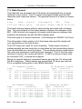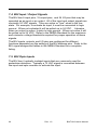
1
BIUT- 820
TS2 Bus Interface Unit Tester
User's Manual
Revision 1.0
Table of Contents
1. Explanation of Symbols, Terms, and Abbreviations..............................3
2. Safety Information................................................................................5
3. Introduction........................................................................................... 6
4. BIUT-820 Software Installation.............................................................7
4.1. Computer Requirements..............................................................7
4.2. BIUT-820 Interface Software Installation......................................7
4.3. BIUT-820 USB Driver Installation.................................................7
5. Running Tests.......................................................................................9
5.1. Testing a BIU without using a computer.......................................9
5.2. Testing a BIU using the computer interface software..................10
6. Test Descriptions................................................................................12
6.1. Power Tests................................................................................12
6.2. SDLC Protocol Tests..................................................................13
6.3. Input / Output Tests....................................................................14
7. Summary of TS2-2003 v2.06 Standard..............................................18
7.1. General.......................................................................................18
7.2. SDLC Communications..............................................................18
7.3. Data Format...............................................................................19
7.4. BIU Input / Output Signals .........................................................20
7.5. BIU Opto Inputs..........................................................................20
8. Service and Calibration......................................................................21
9. Limited Warranty and Liability.............................................................22
BIUT-820 User's Manual
Rev. 1.0
1
2
Rev. 1.1
BIUT-820 User's Manual
1. Explanation of Symbols, Terms, and Abbreviations
1. Explanation of Symbols, Terms, and Abbreviations
Graphical Symbols
The following symbols are used on the BIUT-820 enclosure and in this
manual. Anytime one of these symbols is encountered the user should
be aware of the condition described here next to each symbol.
Caution. Risk of danger. Read the Users Manual before
operating the BIUT-820
Terms and Abbreviations
The following is a list of terms and abbreviations used throughout the text
of this manual along with the definition.
Term or Abbreviation
Definition
BIU
Bus Interface Unit
CU
Traffic signal cabinet controller unit.
DR
Detector Rack
mA
milliamperes (thousandths of an amp)
ms
milliseconds (thousandths of a second)
NEMA
National Electrical Manufacturers Association
PC
Personal computer
SDLC
Synchronous Data Link Control. This is the
digital communications link between a BIU and
controller.
Tester
The ATSI BIUT-820 TS2 Bus Interface Unit
Tester
TF
Terminals and Facilities
TS2
A published standard which defines how the
BIU should function.
BIUT - 820 User's Manual
3
Term or Abbreviation
Definition
VDC
Volts DC
Vrms
Volts RMS (root-mean-squared)
4
Rev. 1.0
BIUT-820 User's Manual
2. Safety Information
2. Safety Information
IMPORTANT SAFETY INFORMATION !
READ BEFORE ATTEMPTING TO USE THE BIUT-820 !
The BIUT-820 (Tester) should only be used by qualified and authorized
traffic signal technicians or engineers who are familiar with generally
accepted electrical safety practices as well as local and national safety
codes. To avoid possible electric shock, burns, or fire, read all
information contained in this manual before attempting to use the Tester.
• Do not use the Tester around explosive gas, vapor, or dust.
• Do not use the Tester in a wet environment.
• Do not attempt to open any part of the Tester enclosure.
• Do not put hands , or any object besides a NEMA TS2 BIU , into the
BIU slot.
• Do not attempt to test devices that have been subject to lightning
strikes or other severe electrical stress.
• Only test BIU devices that are designed according to the NEMA
TS2 standard.
• If you are not sure if a device is designed according to the NEMA
TS2 standard, consult the device manufacturer.
• Only use the power cord provided with the Tester.
• The Tester should only be powered from 120V AC / 60Hz.
BIUT - 820 User's Manual
5
3. Introduction
The BIUT-820 TS2 Bus Interface Unit Tester will run a series of tests on
BIU devices that comply with NEMA Standards Publication TS2-2003
v2.06.
The BIU is a key component in a modern NEMA TS2 signal cabinet. It is
responsible for converting all the inputs and outputs that need to be
controlled and monitored by the controller into a digital data stream. The
data is transmitted to and received from the controller over a
Synchronous Data Link Control (SDLC) connection.
The only link between the BIU and the controller unit is the SDLC
connection. This makes testing individual BIUs extremely difficult outside
of a fully functional TS2 cabinet. Even then, only limited testing is
possible because built-in TS2 controller diagnostic capabilities are
extremely limited. This situation has created the need for a
comprehensive standalone BIU Tester.
The BIUT-820 is housed in an industry standard 19" rack mount type
enclosure with a 3U height. A rugged carrying case is also available as
an option.
6
Rev. 1.0
BIUT-820 User's Manual
4. BIUT-820 Software Installation
4. BIUT-820 Software Installation
4.1. Computer Requirements
Windows XP (minimum)
At least one available USB port.
Adobe Acrobat Reader must be installed. (This can be downloaded for
free at www.adobe.com).
4.2. BIUT-820 Interface Software Installation
Installation of the software is a simple process. However it may require
an administrative access to the computer.
The BIUT-820 comes with a software CD which can be used to install the
software. If the CD is not available, the software can be downloaded from
the Internet. To download the software visit our website:
www.atsi-tester.com.
To install the software from a CD , insert the CD into drive of the
computer. A start-up screen should open automatically. In the start-up
screen click the "BIUT-820" button, then follow the instructions in the
software installation wizard.
To install the software that was downloaded from our website , doubleclick the downloaded executable file to run the installation. Follow the
instructions in the software installation wizard.
Note: Do not forget to install the ATSI Tester USB device
driver for BIUT-820.
4.3. BIUT-820 USB Driver Installation
To communicate with the BIUT-820 an ATSI Tester USB driver needs to
be installed. The same driver is used with several ATSI products and is
included on the software installation CD. The latest version of the driver
can also be downloaded from our website: www.atsi-tester.com. The
driver installation package is also copied to the computer during the
software installation.
To install the USB device driver from a CD , insert the CD into the drive
of the computer. A start-up screen should open automatically. In the startup screen click "ATSI Tester USB Driver" button, then follow the
instructions in the device driver installation wizard.
To install the USB device driver package that was downloaded from our
BIUT - 820 User's Manual
7
website, double-click the downloaded executable file to run the
installation. Follow the instructions in the device driver installation wizard.
To install the USB device driver from the package copied during software
installation , open My Computer and navigate to the directory where the
BIUT-820 Interface software was installed. In that directory, open the
folder caller "driver" and run dpinst.exe and follow the instructions.
8
Rev. 1.0
BIUT-820 User's Manual
5. Running Tests
5. Running Tests
Plug in the Tester :
Before running a test make sure the Tester is plugged into a standard
120V AC / 60Hz outlet using the power cable that is provided.
Put the BIU in the slot :
Slide the BIU into the yellow slot on the Tester. Make sure that the BIU
printed circuit card edges are lined up with the card guides.
Be sure to push the BIU all the way in until the connector is fully
engaged. The faceplate of the BIU should be flush with the front of the
Tester when the connector is fully engaged.
Connect the SDLC cable :
Once the BIU is installed in the yellow slot, connect the provided SDLC
cable from the SDLC port on the front of the Tester to the SDLC port on
the front of the BIU.
Start the tests :
The preferred method of controlling the Tester is to use the BIUT-820
computer interface software. This will allow the user to enter information
about the BIU that is being tested and also allow the test reports to be
saved. The software will also record specific information about each
failure that may be detected.
For situations where simple "good" or "bad" functional testing of a BIU is
all that is required, the tests may be started without using the computer
interface software.
Details for both methods are given in the following sections.
5.1. Testing a BIU without using a computer
For simple "good" or "bad" testing of a BIU, it is not necessary to use the
computer software. The tests can be started by using the push buttons
and display located on the front of the Tester.
1. Turn the Tester power switch to the ON position.
2. After a power-up sequence, the Tester display will show the main
menu.
3. Push the NEXT button to move the cursor ( -> ) and select one of the
two testing options. RUN SELECTED TESTS will allow you to choose
which test to run.
BIUT - 820 User's Manual
9
RUN ALL TESTS will run all of the tests that are available.
->RUN SELECTED TESTS
RUN ALL TESTS
SETUP
INFO
RUN SELECTED TESTS
->RUN ALL TESTS
SETUP
INFO
4. When the cursor is pointing to the desired option, push the ENTER
button to begin the tests. If RUN ALL TESTS was chosen, the tests
will begin automatically. If RUN SELECTED TESTS was chosen,
push the NEXT button until the desired test is shown, then press
ENTER to begin the test.
If you would like to return to the main menu without running a test,
keep pushing the NEXT button until you see :
->RETURN TO MAIN MENU
Then press the ENTER key.
5.2. Testing a BIU using the computer interface software
The preferred method of testing is to use the BIUT-820 computer
interface software to control the Tester. The software will allow you to
enter more complete information about the BIU that is being tested and
save the test reports. You will also be able to view more detailed
information about each test failure that may occur.
To start a test using the software :
1. Connect a USB cable from the computer to the USB port on the front
of the Tester. Note : Before you can go any further, the USB driver
must be installed. Refer to the USB Driver Installation section of this
manual.
2. Turn the tester power switch to the ON position.
3. Start the BIUT-820 software.
10
Rev. 1.0
BIUT-820 User's Manual
5. Running Tests
4. From the BIUT-820 software click on the Test Setup tab and fill in the
data. All information is optional except for the BIU Serial Number.
5. Click on the Run Tests tab and select the tests that you would like to
run.
6. Select One Lap or Multiple Laps. A lap is defined as one time
through all of the selected tests.
7. Click the Start button when you are ready to begin testing.
8. You will be prompted to verify that the information you have entered is
correct. If you click yes, the testing will continue. If you click no, the
testing will not continue and you may re-enter any information that is
not correct and then press the Start button again when you are ready
to begin testing.
Note: If you hover your mouse pointer over any of the
objects in the BIUT-820 software, a help hint will appear in
the status bar at the bottom of the window.
BIUT - 820 User's Manual
11
6. Test Descriptions
All of the BIUT-820 tests are based on NEMA Standards Publication
TS2-2003 v2.06. It is the intent of ATSI to test the requirements of the
aforementioned standard according to the most generally accepted
interpretation. It is recommended that the user run all available tests.
However, the operation of some BIUs may deviate from the standard in a
known and repeatable fashion due to the design of the hardware or
firmware. Furthermore, an individual jurisdiction (state, city, county) may
have specific requirements or practices that are routinely followed which
deviate from the standard or ignore certain parts. In such cases, the
user has the option to disable the testing of certain BIU functions. ATSI
has no authority to enforce compliance with any part of the standard. It
is the responsibility of the user to determine what tests are appropriate
for their local requirements.
6.1. Power Tests
Power-up Initialization Test
Test description :
The BIU address pins are set to TF BIU 1 and the BIU is powered-up
with 24 VDC. The state of the output pins is checked and then Type 10
frames are sent.
Response required to pass :
The BIU outputs must be set to the 24 VDC level at power-up and the
BIU must be fully functional within 1000 ms (TS2-2003 v2.06, Section
8.5.1).
Supply Current Test
Test description :
The BIU is powered up with 26 VDC, all the inputs are set to the active
state and the supply current is measured.
Response required to pass :
Measured DC supply current must be less than 200 mA (TS2-2003
v2.06, Section 8.5).
700 ms Power Loss Test
Test Description :
The BIU address pins are set to TF BIU 1 and the BIU is powered-up
12
Rev. 1.0
BIUT-820 User's Manual
6. Test Descriptions
with 24 VDC. Type 10 command frames are sent to set the BIU outputs
to a specific pattern. The state of the outputs is verified. The 24 VDC
power is set to 0 VDC for less than 700 ms and then restored. The state
of the outputs is checked.
Response required to pass :
The state of the output pins must be the same as before the power was
set to 0 VDC (TS2-2003 v2.06, Section 8.5.1)
1500 ms Power Loss Test
Test description :
The BIU address pins are set to TF BIU 1 and the BIU is powered-up
with 24 VDC. Type 10 command frames are sent to set the BIU outputs
to a specific pattern. The state of the outputs is verified. The 24 VDC
power is set to 0 VDC for 1500 ms and then restored. The state of the
output pins is checked.
Response required to pass :
The BIU outputs must be set to the 24 VDC level (TS2-2003 v2.06,
Section 8.5.1).
Comm Cease Test
Test description :
The BIU address pins are set to TF BIU 1 and the BIU is powered-up
with 24 VDC. Type 10 command frames are sent and the proper BIU
response is verified. The 24 VDC power is then set to 0 VDC. After a 9
ms delay a Type 10 command frame is sent and the response is
checked. The BIU is then powered-up with 24 VDC. After a delay of
200ms, Type 10 command frames are sent and the proper BIU response
is verified.
Response required to pass :
There must be no response from the BIU after the 9 ms delay (comm
cease) . There must be a valid response from the BIU after the 200ms
delay ( comm restore) (TS2-2003 v2.06, Section 8.5.1).
6.2. SDLC Protocol Tests
CRC Test
Test description :
The BIU address pins are set to TF BIU 1 and the BIU is powered-up
BIUT - 820 User's Manual
13
with 24 VDC. Type 10 command frames are sent and the proper
response is verified. Next a Type 10 command frame is sent with a one
bit error in the CRC bytes.
Response required to pass :
There must be no response from the BIU to the Type 10 command frame
with a one bit CRC error (TS2-2003 v2.06, Section 3.3.1.4.2.4).
Correct Address Response Test
Test description :
The BIU address pins are set to TF BIU 1* and the BIU is powered-up
with 24 VDC. Valid command frames addressed to each of the TF BIUs
are sent.
Response required to pass :
The BIU must only respond to command frames with addresses that
match the address pins (TS2-2003 v2.06, Section 3.3.1.3).
* The test is repeated when the BIU address is set to all of the other valid
TF and DR addresses.
6.3. Input / Output Tests
Input 1 - 8 Recognition Test
Test description :
The BIU address pins are set to TF BIU 1* and the BIU is powered-up
with 24 VDC. Each BIU input is set to the active state while all others are
set to the inactive state. Command frames are sent and the response is
verified.
Response required to pass :
The proper bits must be set in the BIU response frame to indicate that
the BIU is reading the inputs correctly (TS2-2003 v2.06, Section 3.3.5.1.3
and 8.8.5).
* The test is repeated when the BIU address is set to all of the other valid
TF addresses
Opto Input 1- 4 Recognition Test
Test description :
The BIU address pins are set to TF BIU 1* and the BIU is powered-up
14
Rev. 1.0
BIUT-820 User's Manual
6. Test Descriptions
with 24 VDC. An 8.5 Vrms sine wave is applied to each opto input one at
a time. Command frames are sent and the response is verified.
Response required to pass :
The proper bits must be set in the BIU response frame to indicate that
the BIU is reading the opto inputs correctly (TS2-2003 v2.06, Section
8.8.5 and 8.8.5.2).
* The test is repeated when the BIU address is set to all of the other valid
TF addresses
I/O 14 - 24 Recognition Test
Test Description :
The BIU address pins are set to TF BIU 1 and the BIU is powered-up
with 24 VDC. BIU I/O pins 14 - 24 are set to the active state one at a
time. Command frames are sent and the response is verified.
Response required to pass :
I/O pins 14 - 24 must be recognized as inputs to TF BIU 1. The proper
bits must be set in the response frame to indicate that the BIU is reading
the inputs correctly (TS2-2003 v2.06, Section 3.3.5.1.3 and 8.8.5 and
5.3.1.4.2).
I/O 16 - 20 Recognition Test
Test Description :
The BIU address pins are set to TF BIU 2 and the BIU is powered-up
with 24 VDC. BIU I/O pins 16 - 20 are set to the active state one at a
time. Command frames are sent and the response is verified.
Response required to pass :
I/O pins 16 - 20 must be recognized as inputs to TF BIU 2. The proper
bits must be set in the response frame to indicate that the BIU is reading
the inputs correctly (TS2-2003 v2.06, Section 3.3.5.1.3 and 8.8.5 and
5.3.1.4.2).
I/O 7 - 24 Recognition Test
Test Description :
The BIU address pins are set to TF BIU 3 and the BIU is powered-up
with 24 VDC. BIU I/O pins 7 - 24 are set to the active state one at a time.
Command frames are sent and the response is verified.
BIUT - 820 User's Manual
15
Response required to pass :
I/O pins 7 - 24 must be recognized as inputs to TF BIU 3. The proper
bits must be set in the response frame to indicate that the BIU is reading
the inputs correctly (TS2-2003 v2.06, Section 3.3.5.1.3 and 8.8.5 and
5.3.1.4.2).
I/O 10 - 14 Recognition Test
Test Description :
The BIU address pins are set to TF BIU 4 and the BIU is powered-up
with 24 VDC. BIU I/O pins 10 - 14 are set to the active state one at a
time. Command frames are sent and the response is verified.
Response required to pass :
I/O pins 10 - 14 must be recognized as inputs to TF BIU 4. The proper
bits must be set in the response frame to indicate that the BIU is reading
the inputs correctly (TS2-2003 v2.06, Section 3.3.5.1.3 and 8.8.5 and
5.3.1.4.2).
Load Switch Driver Test
Test description :
The BIU address pins are set to TF BIU 1* and the BIU is powered-up
with 24 VDC. Command frames are sent to the BIU to set each load
switch diver output one at at time.
Response required to pass :
The state of the BIU load switch pins is sampled. The pin must be in the
active state when the correct bit is set in the command frame (TS2-2003
v2.06, Section 8.8.4 and 5.3.1.4.2).
* The test is repeated when the BIU address is set to TF BIU 2.
Constant Call Recognition Test
Test description :
The BIU address pins are set to DR BIU 1* and the BIU is powered-up
with 24 VDC. Each of the detector channel inputs is set to the active
state one at a time. Command frames are sent and the response is
verified.
Response required to pass :
I/O pins 1 - 16 must be recognized as detector call inputs to DR BIU 1.
The proper bits must be set in the response frame to indicate that the
16
Rev. 1.0
BIUT-820 User's Manual
6. Test Descriptions
BIU is reading a constant call correctly (TS2-2003 v2.06, Section
3.3.1.4.2.6).
BIUT - 820 User's Manual
17
7. Summary of TS2-2003 v2.06 Standard
In order to thoroughly understand the tests performed by the BIUT-820, it
is important to be familiar with NEMA Standards Publication TS2-2003
v2.06, Sections 3 and Sections 8. The information given here is only a
summary of some of the important terminology that is used in the test
descriptions. It is highly recommended that the user obtain a copy of the
complete standard.
7.1. General
The BIU is an important component in a TS2 signal control cabinet. It
acts as the interface between Port 1 of the CU and the TF and Loop
Detector Racks (DR). Its functions include controlling load switch
outputs, detector resets, and communicating with inductive loop
detectors.
The CU sends digital data frames to the BIU which tell it to do a certain
task ( e.g. turn on an output ) or to respond with information (e.g. report
the state of inputs). The data that the controller sends is referred to as a
command frame. The response from a BIU is referred to as a response
frame.
7.2. SDLC Communications
The transmission of data between the CU and BIU takes place by means
of the SDLC protocol. The signal connections are shown below :
CU
Tx
Tx
Tx
Tx
Rx
Rx
Rx
Rx
Data (+)
Data (-)
Clock(+)
Clock(-)
Data (+)
Data (-)
Clock(+)
Clock(-)
-------------------------------------------------------------------------------------------------
BIU
Rx Data (+)
Rx Data (-)
Rx Clock(+)
Rx Clock(-)
Tx Data (+)
Tx Data (-)
Tx Clock(+)
Tx Clock(-)
The data bits are transmitted on the Tx Data lines. Each bit is read at the
receiving station on the rising edge of the Tx Clock signal. The data is
transmitted at a rate of 153,600 bits per second.
18
Rev. 1.0
BIUT-820 User's Manual
7. Summary of TS2-2003 v2.06 Standard
7.3. Data Format
The data bits are arranged into 8 bit bytes and packaged into a format
referred to as a frame. The CU sends command frames and the BIU
responds with response frames. The general format of a frame is shown
below :
Flag
Addr. Control
01111110 8Bits 8bits
Information
CRC
Flag
Variable length 16Bits 01111110
The frame always begins with an opening flag and ends with a closing
flag. The second byte of the frame always contains the address of the
BIU. A BIU should only respond to frames which have an address that
matches the address set with the BIU address pins.
The third byte is a control character. It will always be 10000011 (83 hex).
The information field contains all of the frame data and the length will
vary depending on the frame type.
The CRC bytes are used for error checking. These bytes contain a
mathematically derived code that is calculated by the transmitting device
from the bits that are set in the frame. The receiving device recalculates
the code and compares it with what was received. If all of the bits were
received correctly, the codes will match. If a BIU receives a frame with
an incorrect CRC, it should not respond.
Below is a partial listing of command frames sent by the CU along with
the BIU response. These frames are transmitted 10 times per second.
For a complete listing refer to the NEMA Standard.
TF Command Frames
TF Response Frames
Function
Type
Function
---------------------------- ---- -----------BIU 1 Outputs/Inputs Request
138 BIU 1 Inputs
BIU 2 Outputs/Inputs Request
139 BIU 2 Inputs
BIU 3 Outputs/Inputs Request
140 BIU 3 Inputs
BIU 4 Outputs/Inputs Request
141 BIU 4 Inputs
Type
---10
11
12
13
DR Command Frames
DR Response Frames
Function
Type
Function
----------------------- ---- --------------BIU 1 Call Data Request
148 BIU 1 Call Data
BIU 2 Call Data Request
149 BIU 2 Call Data
BIU 3 Call Data Request
150 BIU 3 Call Data
BIU 4 Call Data Request
151 BIU 4 Call Data
Type
---20
21
22
23
BIUT - 820 User's Manual
19
7.4. BIU Input / Output Signals
The BIU has 8 input pins, 15 output pins, and 24 I/O pins that may be
operated as an input or an output. All of the input and output signals are
nominally 24 VDC signals. They are active or "true" when in the low
state. For example, to activate an input, it must be connected to logic
ground. When not activated it will be pulled up to 24 VDC. Likewise,
when an output is active, it sinks to logic ground. When not active it will
be pulled up to 24 VDC. Refer to the NEMA Standard for the maximum
and minimum voltage thresholds required for proper operation of these
signals.
The BIU inputs, outputs, and I/O pins are configured for different
functions depending on the setting of the BIU address pins. Refer to the
BIU signal assignment tables in the NEMA Standard for a complete
listing.
7.5. BIU Opto Inputs
The BIU has 4 optically isolated inputs that are commonly used for
pedestrian detectors. Typically a 12 VAC signal is connected between
the input and opto common to activate the input.
20
Rev. 1.0
BIUT-820 User's Manual
8. Service and Calibration
8. Service and Calibration
The BIUT-820 has no user serviceable parts. Under no circumstances
should the user attempt to open the enclosure. If the tester appears to be
malfunctioning, contact ATSI to make arrangements for repair. See the
Limited Warranty and Liability section of this manual for details.
ATSI strongly recommends that each Tester be calibrated yearly. A
yearly calibration will verify that your Tester is operating within the
original manufacturers specifications and provide you with a detailed
calibration report for documentation. Please visit www.atsi-tester.com for
the latest pricing of calibration services and extended maintenance
plans.
BIUT - 820 User's Manual
21
9. Limited Warranty and Liability
The BIUT-820 TS2 Bus Interface Unit Tester (Product), distributed by
Athens Technical Specialists, Inc. (ATSI), is warranted to the original
purchaser (Purchaser) to be free of defects in materials and
workmanship for a period of one year from the purchase date stated on
the invoice. Within this period, in the event of a defect, malfunction, or
other failure of the Product while in the custody of the Purchaser, ATSI
will remedy the defect or cause of failure without charge to the
Purchaser. The Purchaser's sole remedy is restoration of product
operation. ATSI accepts no liability for incidental or related expenses.
Under no circumstances will ATSI's liability exceed the purchase price for
items claimed to be defective.
This Limited Warranty does not extend to any Product that has been
damaged or rendered defective as a result of accident, misuse, abuse,
modification of the product, or service by anyone other than ATSI.
EXCEPT AS EXPRESSLY SET FORTH IN THIS WARRANTY, ATSI
MAKES NO OTHER WARRANTIES, EXPRESS OR IMPLIED,
INCLUDING ANY IMPLIED WARRANTIES OF MERCHANTABILITY
AND FITNESS FOR A PARTICUALR PURPOSE OF THE PRODUCT
AND ANY DEVICE TESTED BY THE PRODUCT. ATSI EXPRESSLY
DISCLAIMS ALL WARRANTIES NOT STATED IN THIS LIMITED
WARRANTY. ANY IMPLIED WARRANTIES THAT MAY BE IMPOSED
BY LAW ARE LIMITED TO THE TERMS OF THIS EXPRESS LIMITED
WARRANTY.
Warranty Repair
To return the Product for repairs covered under the Limited Warranty :
Request a Return Merchandise Form by phone, fax, or email from the
ATSI Service Department or complete the form at www.atsi-tester.com.
Return the Product along with the completed form with prepaid postage
to :
ATSI
8157 US Hwy 50
Athens, OH 45701
Phone: (740) 592 - 2874
Fax: (740) 594 - 2875
Email: [email protected]
22
Rev. 1.0
BIUT-820 User's Manual
BIUT-820 User's Manual
Rev. 1.0
23
TS2 Bus Interface Unit Tester
Model BIUT-820
User's Manual
Revision 1.0