1
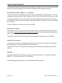
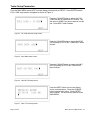
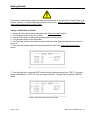
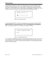
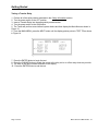
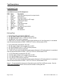
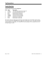
MST-700
Multi Switch Tester
For Load Switch, Flasher and Transfer Relay
User's Manual
Revision 1.0
Contacting ATSI :
ATSI
8157 US Route 50
Athens, OH 45701
740-592-2874
Fax : 740-594-2875
www.atsi-tester.com
Email for purchasing information :
[email protected]
Email for service :
[email protected]
Table of Contents
Explanation of Symbols, Terms and Abbreviations ...........................................
2-3
Safety Information ...........................................................................................
4-6
Introduction .......................................................................................................
7
Operator Interface and Pushbutton Descriptions .............................................
8
Tester Setup Parameters .................................................................................
9 - 10
Getting Started .................................................................................................
11 - 13
Test Descriptions ..............................................................................................
14 - 17
Electrical and Mechanical Specifications .........................................................
18
Service and Calibration ....................................................................................
19
Limited Warranty and Return Merchandise .....................................................
20
Page 1 of 20
MST-700 User's Manual Rev. 1.0
Explanation of Symbols, Terms and Abbreviations
`
Graphical Symbols
The following symbols are used on the MST-700 enclosure and in this manual. Anytime one of these
symbols is encountered the user should be aware of the condition described here next to each symbol.
Caution. Risk of danger. Read the Users Manual before operating the MST-700.
Caution. Hot Surface.
Terms and Abbreviations
The following is a list of terms and abbreviations used throughout the text of this manual along with the
definition.
Term or Abbreviation
Definition
Caltrans
California Department of Transportation
Flasher
Solid state device used to flash traffic signal lamps by turning the power
on and off at a predetermined rate.
FL
Flasher (see definition of Flasher)
FPM
Flashes per minute
Load Switch
Solid state device used to switch the power to traffic signal lamps.
LS
Load Switch (see definition of Load Switch)
mA
milliamperes (thousandths of an amp)
ms
milliseconds (thousandths of a second)
NEMA
National Electrical Manufacturers Association
PC
Personal computer
Tester
The ATSI MST-700 Multi Switch Tester.
Transfer Relay
An electro-mechanical relay used in a traffic signal electrical cabinet.
TR
Transfer Relay (see definition of Transfer Relay)
Page 2 of 20
MST-700 User's Manual Rev. 1.0
Explanation of Symbols, Terms and Abbreviations
`
Term or Abbreviation
Definition
TS 1
Traffic Control Systems Standard published by NEMA (see NEMA).
TS 2
Traffic Control Systems Standard published by NEMA (see NEMA).
VDC
Volts DC
Vrms
Volts RMS (root-mean-squared)
Page 3 of 20
MST-700 User's Manual Rev. 1.0
Safety Information
IMPORTANT SAFETY INFORMATION !
READ BEFORE ATTEMPTING TO USE THE MST-700 !
The MST-700 (Tester) should only be used by qualified and authorized traffic signal technicians who
are familiar with generally accepted electrical safety practices as well as local and national safety
codes. To avoid possible electric shock, burns, or fire, read all information contained in this manual
before attempting to use the Tester.
•
•
•
•
•
•
•
•
Do not use the Tester around explosive gas, vapor, or dust.
Do not use the Tester in a wet environment.
Do not use the Tester outdoors.
Do not use the Tester in an area where the ambient air temperature is greater than 80° F.
Do not attempt to open any part of the Tester enclosure.
Do not place anything on top of the Tester.
Do not block the air ventilation openings on the sides or bottom of the Tester.
Do not block the cooling fans located in the rear of the Tester.
The Tester must dissipate large amounts of power (heat) during certain tests. It is therefore extremely
important to verify that both cooling fans are operating and all ventilation openings are free from
obstructions before attempting to run any tests.
Before starting any tests do all of the following (also see Figure 1 and Figure 2) :
•
•
•
•
•
•
•
•
•
Place the Tester on a solid surface.
Leave at least 10 inches of clearance in the front and rear of the Tester.
Leave at least 6 inches of clearance on each side of the Tester.
Verify that there is approximately a 0.5" inch gap between the bottom of the Tester front panel
and the surface on which it is resting. (The tester should be resting on 4 feet located on the
bottom.)
Verify that there is nothing on top of the tester.
Plug in the Tester to a three pronged, grounded, 120 Vrms AC outlet. Use only the power cord
provided with the Tester. Do not use an extension cord.
Turn the Tester power switch to the ON position.
Visually verify that both Tester cooling fans are operating.
Verify that no obstructions are covering the ventilation holes on either side of the Tester.
Page 4 of 20
MST-700 User's Manual Rev. 1.0
Safety Information
Figure 1. Tester placement.
Figure 2. Minimum clearance distances.
The Tester is equipped with an internal temperature measurement sensor and, if necessary, will not
allow a new test to begin if the Tester temperature is too high. Also, if necessary, the Tester will go
through a cool down cycle at the end of a test. Do not shut off power to the tester during the cool down
cycle. If power is lost before the Tester has completed the cool down cycle, the enclosure surfaces
may be hot.
Page 5 of 20
MST-700 User's Manual Rev. 1.0
Safety Information
The Tester is designed to test ONLY Load Switches, Flashers, and Transfer Relays that are designed
in accordance with NEMA TS1, TS 2, or Caltrans Traffic Signal Control Equipment Specifications.
If you are not sure if a device meets this criteria, do not attempt to test it !
Do not attempt to insert any other type of device or object into the test sockets.
Always turn the Tester power switch to the OFF position before inserting or removing a device.
Page 6 of 20
MST-700 User's Manual Rev. 1.0
Introduction
MST-700 Multi Switch Tester
The MST-700 is an automated tester designed to test Load Switches, Flashers, and Transfer Relays
that are used in traffic signal installations conforming with NEMA or Caltrans Specifications.
Operator Interface
The operator interface consists of a 4 line by 20 character vacuum fluorescent display and 3
pushbuttons. All test setup parameters are entered via this interface. The results of each test are
shown on the display. See the Operator Interface and Pushbutton Descriptions section of this manual
for detailed instructions.
Test Report
A pass / fail report may be generated for the Load Switch and the Flasher. Reports may be stored on
an optional SD memory card. The memory card may be read by any computer equipped with a card
reader.
Tested Parameters
The following parameters are tested for each device. See the Test Descriptions section of this manual
for a detailed test descriptions.
Load Switch Tests
Inputs : On/Off Voltage thresholds
Inputs : Max input current
Outputs : Max off-state current
Outputs : Max load current
Outputs : Min load current
Page 7 of 20
Flasher Tests
Outputs : Flashes per minute
Outputs : Percentage on time
Outputs : Overlap time
Transfer Relay Tests
Outputs : Continuity
MST-700 User's Manual Rev. 1.0
Operator Interface and Pushbutton Descriptions
The operator interface consists of a 4 line by 20 character vacuum fluorescent display, three
pushbuttons, an RS-232 port, an SD memory card slot, and an ON / OFF switch (see Figure 3). All
tester setup parameters and data are entered with the three pushbuttons labeled NEXT, CHANGE, and
ENTER.
The SD memory card slot is provided so that test reports may be saved to an SD card if desired. Once
saved to an SD card, the test reports may be read by a PC equipped with an SD card reader. Saving
reports to the SD card is optional and may be enabled or disabled using the SETUP screen. See the
Tester Setup Parameters section of this manual for details.
NOTE : To insert the SD card into the slot gently push the card in as far as it will go and then remove
pressure. The card should make a clicking sound and then lock into place. To remove the SD card,
gently push in on the card as far as it will go and then remove pressure. The card should unlock and
partially eject. It is then free to be removed. DO NOT PULL OUT ON THE CARD WHEN IT IS IN THE
LOCKED POSITION. Doing so will damage the connector.
The RS-232 port is provided for connection to a PC for future firmware upgrades and is not needed for
normal Tester operation.
Figure 3. Operator Interface
Pushbutton Functions
Button
Function
NEXT
Advances the screen pointer ( -> ) or cursor ( █ ) to the next item.
CHANGE
Changes any adjustable parameter pointed to by the screen pointer or
flashing cursor.
ENTER
Executes the function pointed to by the screen pointer or saves the
parameter that was adjusted with the CHANGE button.
Page 8 of 20
MST-700 User's Manual Rev. 1.0
Tester Setup Parameters
The following parameters must be set before you begin running tests. Once set, the Tester stores the
parameters in memory and they do net need to be set again unless a change is required.
Full Load Time ( Range : NONE, or 1 - 30 minutes )
The Full Load test is an optional test that may be ran at the beginning of a Load Switch test. This test
will apply the nominally rated full load (10 Amps at 120 Vrms) to each Load Switch output one at a time.
For example, if the time is set to 15 minutes, the load will be applied to the red output for 20 seconds,
then the yellow output for 20 seconds, and then the green output for 20 seconds. This cycle will repeat
for 15 minutes.
If you do not wish to run this test, set the value to NONE.
Save Data ( Yes or No )
If Save Data is set to Yes, the results of a Load Switch or Flasher test will be saved to an SD memory
card. See the Operator Interface and Pushbutton Descriptions section of this manual for instructions
on how to insert and remove the SD memory card.
If Save Data is set to No, the test results will not be saved and will only be shown on the display.
Halt On Fail ( Yes or No )
If Halt On Fail is set to Yes, a Load Switch or Flasher test will halt on any test failure. The failure will
be displayed on the screen until the NEXT button is pressed.
If Halt On Fail is set to No, each failure will be displayed on the screen as it happens but the test will
continue.
Set Clock
The clock ( date and time ) must be set correctly in order to save reports. The format for the date is :
MM/DD/YY. The format for time is HH : MM AM/PM.
The following pages will guide you step by step through the Setup process.
Page 9 of 20
MST-700 User's Manual Rev. 1.0
Tester Setup Parameters
From the MAIN MENU press NEXT until the display pointer points to SETUP. Press ENTER and the
FULL LOAD setup screen will appear as shown in Figure 4.
Press the CHANGE button to adjust the FULL
LOAD test time in increments of 1 minute. Set
this value to NONE if you do not want to run this
test. Press NEXT when finished.
Figure 4. Full Load test time setup screen.
Press the CHANGE button to toggle the SAVE
DATA setting to YES or NO. Press NEXT when
finished.
Figure 5. Save Data setup screen.
Press the CHANGE button to toggle the HALT
ON FAIL setting to YES or NO. Press NEXT
when finished.
Figure 6. Halt On Fail setup screen.
Press the NEXT button to move the display
cursor to each position. Press the CHANGE
button to adjust each value. Press ENTER
when finished. You will now be returned to the
MAIN MENU.
Figure 7. Date / Time setup screen.
Page 10 of 20
MST-700 User's Manual Rev. 1.0
Getting Started
This section provides step-by-step instructions for running a test on a Load Switch, Transfer Relay, and
Flasher. However, to avoid possible electric shock, burns, or fire, read all information contained in this
manual before attempting to use the Tester.
Testing a Load Switch or Flasher
1. Perform all of the safety checks described in the Safety Information section.
2. Turn the power switch to the OFF position.
3. Insert a Load Switch or Flasher into the appropriately marked socket.
4. Turn the power switch to the ON position.
5. The Tester will perform some internal system checks and then display the Main Menu as shown in
Figure 10.
6. If you have not already adjusted the Setup parameters, refer to the Tester Setup Parameters
section.
Figure 8. Main Menu
7. From the Main menu, press the NEXT button until the display pointer points to TEST LS if you are
testing a Load Switch, or TEST FL if you are testing a Flasher. To begin the test, press the ENTER
button.
Figure 9. Main Menu with TEST LS selected.
Page 11 of 20
MST-700 User's Manual Rev. 1.0
Getting Started
8. If you have set SAVE DATA to YES in the Setup parameters, you will see the following "ENTER
DEVICE ID" screen as shown in Figure 12. You must enter a valid device ID. The ID may be any
combination of numbers or letters. The minimum length is 1 character and the maximum length is 16
characters. Press the CHANGE button to change the character indicated by the flashing cursor. Press
the NEXT button to move the cursor to the next character. Press ENTER when complete.
Figure 10. Enter Device ID screen
9. If you have set SAVE DATA to YES in the Setup parameters, you will see the following "SELECT
MANUFACTURER" screen as shown in Figure 13. Press the CHANGE button to scroll through the
different manufacturers. Press the ENTER button when you have selected the correct manufacturer.
(Note : If the correct manufacturer is not on the list, you may select "OTHER".)
Figure 11. Select Manufacturer screen
10. The test will now proceed and the pass / fail results will be displayed on the screen. If you have set
HALT ON FAIL to YES in the Setup parameters, the test will pause on each failure and prompt you to
press the NEXT button to continue. If you have set HALT ON FAIL to NO, the test will proceed without
any further interaction required.
Page 12 of 20
MST-700 User's Manual Rev. 1.0
Getting Started
Testing a Transfer Relay
1. Perform all of the safety checks described in the Safety Information section.
2. Turn the power switch to the OFF position.
3. Insert a Transfer Relay into the appropriately marked socket.
4. Turn the power switch to the ON position.
5. The Tester will perform some internal system checks and then display the Main Menu as shown in
Figure 10.
6. From the MAIN MENU, press the NEXT button until the display pointer points to TEST TR as shown
in Figure 14.
Figure 12. Main Menu with TEST TR selected.
7. Press the ENTER button to begin the test.
8. Press the CHANGE button to toggle the power to the relay coil on or off as many times as you wish.
9. The state of the relay contacts is shown on the display.
10. Press the ENTER button to end the test.
Page 13 of 20
MST-700 User's Manual Rev. 1.0
Test Descriptions
Load Switch Tests
Load Switch Connector Pin Assignment
PIN #
1
2
3
4
5
6
7
8
9
10
11
12
Name
AC Line
EGND
RED OUT
LGND
YEL OUT
RED IN
GRN OUT
YEL IN
DC SUPPLY
GRN IN
NEUT
NC
Description
120 Vrms (nominal) power for output circuits
Earth ground
Red signal output
Logic ground return for DC supply
Yellow signal output
Red input
Green signal output
Yellow input
DC supply for input circuits
Green input
AC neutral
No connection
Full Load Test
1. A 12.5 Ohm load is connected to RED OUT.
2. The DC supply voltage is set to greater than 24 VDC.
3. The RED IN voltage is set to 1.5 VDC for twenty seconds.
4. The RED OUT rms current is measured.
5. If RED OUT rms current is within the nominal range (allowing for AC line fluctuation) it is considered
to be ON and the test status is PASS. If RED OUT is not on, the test status if FAIL.
6. A 12.5 Ohm load is connected to YEL OUT.
7. The DC supply voltage is set to greater than 24 VDC.
8. The YEL IN voltage is set to 1.5 VDC for twenty seconds.
9. The YEL OUT rms current is measured.
10. If YEL OUT rms current is within the nominal range (allowing for AC line fluctuation) it is considered
to be ON and the test status is PASS. If YEL OUT is not on, the test status if FAIL.
11. A 12.5 Ohm load is connected to YEL OUT.
12. The DC supply voltage is set to greater than 24 VDC.
13. The YEL IN voltage is set to 1.5 VDC for twenty seconds.
14. The YEL OUT rms current is measured.
15. If YEL OUT rms current is within the nominal range (allowing for AC line fluctuation) it is considered
to be ON and the test status is PASS. If YEL OUT is not on, the test status if FAIL.
Steps 1 - 15 are repeated for the amount of time that is set in the FULL LOAD setup screen. See the
Tester Setup Parameters section of this manual for details on setting the time.
Page 14 of 20
MST-700 User's Manual Rev. 1.0
Test Descriptions
Input On Threshold
This test verifies that an input voltage of 5.5 VDC will turn the output on when the DC supply voltage is
greater than 22 VDC.
1. A 1200 Ohm load is applied to RED OUT.
2. The DC supply voltage is set to greater than 22 VDC.
3. The RED IN voltage is set to 5.5 VDC.
4. The RED OUT rms current is measured.
5. If RED OUT rms current is within the nominal range (allowing for AC line fluctuation) it is considered
to be ON and the test status is PASS. If RED OUT is not on, the test status if FAIL.
Input Off Threshold
This test verifies that an input voltage of 16.5 VDC will turn the output off when the DC supply voltage is
less than 26 VDC.
1. A 1200 Ohm load is applied to RED OUT.
2. The DC supply voltage is set to less than 26 VDC.
3. The RED IN voltage is set to 16.5 VDC.
4. The RED OUT peak current is measured.
5. If RED OUT peak current does not exceed 10 mA, it is considered to be OFF and the test status is
PASS. If the RED OUT peak current is greater than 10 mA, the test status is FAIL.
Maximum Input Current
This test verifies that a Load Switch input circuit will not draw more than 20 mA when the DC supply is
between 22 and 26 VDC.
1. The DC supply voltage is set to less than 26 VDC.
2. The RED IN voltage is set to 1.5 VDC.
3. The RED IN current is measured.
4. If the RED IN current is 20 mA or less the test status is PASS. If the RED IN current is greater than
20mA, the test status is FAIL.
The Input On Threshold, Input Off Threshold, and Maximum Input Current tests are repeated for the
YEL and GRN channels.
Page 15 of 20
MST-700 User's Manual Rev. 1.0
Test Descriptions
Flasher Tests
Flasher Connector Pin Assignment
Pin#
7
8
9
10
11
12
Name
OUTPUT 1
OUTPUT 2
EGND
NEUT
AC LINE
NC
Description
Load circuit #1
Load circuit #2
Earth ground
AC neutral
120 Vrms (nominal) power for Flasher and output circuits
No connection
Data Collection
1. A 1200 Ohm load is applied to OUTPUT 1 and OUTPUT 2.
2. AC line voltage is applied to the AC LINE pin.
3. Voltage and current data is collected for OUTPUT 1 and OUTPUT 2 for 10 seconds.
Flashes Per Minute Test
The FPM rate for OUTPUT 1 and OUTPUT 2 is calculated from the data collected. If the FPM rate is
between 50 and 60, the test status is PASS. If the FPM rate is less than 50 or greater than 60, the test
status is FAIL.
On Period Test
The on period for OUTPUT 1 and OUTPUT 2 is calculated. If the on period is between 45 and 55 %,
the test status is PASS. If the on period is less than 45 or greater than 55 %, the test status is FAIL.
Same State Overlap Test
The maximum amount of time that OUTPUT 1 and OUTPUT 2 are in the same state (i.e. both on or
both off ) is calculated. If the maximum overlap time is greater than 17 ms, the test status is FAIL. If
the maximum overlap time is 17 ms or less, the test status is PASS.
Page 16 of 20
MST-700 User's Manual Rev. 1.0
Test Descriptions
Transfer Relay Tests
Transfer Relay Connector Pin Assignment
Pin#
1
2
3
4
5
6
7
8
Name
Coil AC
Coil Neut
NC-A
NC-B
COMMA
COMMB
NO-A
NO-B
Description
120 Vrms (nominal) power for relay coil
AC neutral connection for relay coil
Normally closed contact (A)
Normally closed contact (B)
Common for NC-A and NO-A
Common for NC-B and NO-B
Normally open contact (A)
Normally open contact (B)
The transfer relay test verifies proper functioning of the normally open and normally closed contacts.
The user may press the CHANGE button to toggle the Coil AC power on or off. The state of the relay
contacts is shown on the display. If a contact fails to function properly, FAIL is indicated next to the
corresponding pin number.
Page 17 of 20
MST-700 User's Manual Rev. 1.0
Electrical and Mechanical Specifications
Electrical
Operating Voltage
Operating Current
Cooling
Data Storage Media
: 120 VAC, 60Hz
: 12 Amps full load
: Fan Cooled
: SD memory card, 64 MB, SanDisk or equivalent
Mechanical
Enclosure
Dimensions
Weight
Environment
Operating Temperature Range
: 3U Rackmount Type
: 19.3" (W) x 20.5" (D) x 5.25" (H)
: 22 lbs.
: Indoor laboratory use only
: 32 º F to 80 º F ambient air temperature
Page 18 of 20
MST-700 User's Manual Rev. 1.0
Service and Calibration
The MST-700 Tester has no user serviceable parts. Under no circumstances should the user attempt
to open the Tester enclosure. If the Tester appears to be malfunctioning, contact ATSI to make
arrangements for repair. See the Limited Warranty section of this manual for details.
ATSI strongly recommends that each Tester be calibrated yearly. A yearly calibration will verify that
your Tester is operating within the original manufacturers specifications and provide you with a detailed
calibration report for documentation. Please visit www.atsi-tester.com for the latest pricing of
calibration services and extended maintenance plans.
Page 19 of 20
MST-700 User's Manual Rev. 1.0
Limited Warranty and Return Merchandise
The MST-700 (Product), distributed by Athens Technical Specialists, Inc. (ATSI), is warranted to the
original purchaser (Purchaser) to be free of defects in materials and workmanship for a period of one
year from the purchase date stated on the invoice. Within this period, in the event of a defect,
malfunction, or other failure of the product while in the custody of the Purchaser, ATSI will remedy the
defect or cause of failure without charge to the Purchaser. The Purchaser's sole remedy is restoration
of product operation. ATSI accepts no liability for incidental or related expenses. Under no
circumstances will ATSI's liability exceed the purchase price for items claimed to be defective.
This Limited Warranty does not extend to any Product that has been damaged or rendered defective as
a result of accident, misuse, abuse, modification of the product, or service by anyone other than ATSI.
EXCEPT AS EXPRESSLY SET FORTH IN THIS WARRANTY, ATSI MAKES NO OTHER
WARRANTIES, EXPRESS OR IMPLIED, INCLUDING ANY IMPLIED WARRANTIES OF
MERCHANTABILITY AND FITNESS FOR A PARTICUALR PURPOSE. ATSI EXPRESSLY
DISCLAIMS ALL WARRANTIES NOT STATED IN THIS LIMITED WARRANTY. ANY IMPLIED
WARRANTIES THAT MAY BE IMPOSED BY LAW ARE LIMITED TO THE TERMS OF THIS
EXPRESS LIMITED WARRANTY.
Warranty Repair
What you must do to return the Product for repairs covered under the Limited Warranty :
Request a Return Merchandise Form by phone, fax, or email from the ATSI Service Department or
complete the form at www.atsi-tester.com. Return the Product along with the completed form with
prepaid postage to :
ATSI
8157 US Route 50
Athens, OH 45701
(740) 592 - 2874
(740) 594 - 2875 Fax
[email protected]
Note : To protect your Product against in-transit damage or loss, it is recommended that all shipments
be insured.
Page 20 of 20
MST-700 User's Manual Rev. 1.0