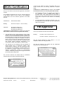
1
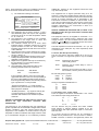
Alternatively, the IS-L101L beacon may be mounted
directly onto a IS-A105N sounder enclosure and
secured using a joining kit which is available from
European Safety Systems Ltd.
brightness of each device. Sounders must not be powered
from beacons connected in parallel.
c. Finally connect the field wiring to the removable
terminals, replace the lens and tighten the two captive
screws.
Ci = 0
28V
660mA
1.2W
Li = 0
Ac.Sw
However if an IS-A105N sounder was used in conjunction
with the beacon a barrier with output parameters 28V 93mA
and 660mW where Io is resistively limited must be used (see
sounder certificate) so then the S+ and S- terminal safety
parameters are equal to or less than:
Uo
Io
Po
=
=
=
Ci = 0
28V
93mA
660mW
Li = 0
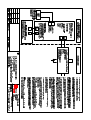
If the beacon and sounder are mounted apart, for intrinsic
safety assessment the capacitance and inductance of the
interconnecting cable should be added to that of the cable
connecting the barrier or isolator to the beacon. See section
4.3.
4.5 Terminals Ac.Sw - accept switch
The output safety parameters of these terminals are:
Uo
Io
Po
=
=
=
16.8V
3.61mA
15.2mW
They may be connected to any mechanically operated switch
in the same hazardous area as the beacon providing the
switch has an IP protection suitable for the environmental
conditions to which it is subjected and can withstand a 500V
rms insulation test to earth for 1 minute.
ON
=
=
=
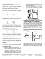
PS TS T4 T3 T2 T1
Uo
Io
Po
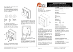
+ - S+ S-
4.4 Terminals S+ and S- connection for optional sounder
These terminals have the same maximum output safety
parameters as the Zener barrier or isolator powering the
beacon, i.e. they are equal to or less than:
1 2 3 4 5 6
The equivalent capacitance and inductance between
terminals + and - of the IS-L101Lbeacon and between
terminals + and - of the IS-A105N sounder are zero.
The maximum permitted cable parameters defined by the
barrier or isolator certificate must not be exceeded.
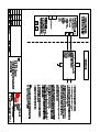
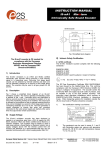
Fig 2 Location of field terminals and controls.
6. ELECTRICAL SYSTEM DESIGN FOR INSTALLATION IN
HAZARDOUS AREAS USING ZENER BARRIERS
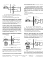
6.1 Stand alone operation
If the beacon is controlled by a switch in the positive supply,
or the power supply is being turned on and off, only a single
channel Zener barrier is required as shown in Fig 3. This
circuit may also be used if the beacon is being controlled by a
mechanically activated switch on the hazardous area side of
the barrier. The power supply voltage should be between 20V
and the maximum working voltage of the barrier. The circuit
will continue to work at lower voltages, but the beacon
brilliance will be reduced.
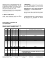
Note when the beacon is operated on its own, without a
sounder connected, all of the DIP switches should be set
to OFF position.
Hazardous Area
Safe Area
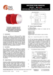
IS-L101L
Beacon
Ac.Sw
28V 1.2W
Positive
+
-
+
Barrier
On/Off
5. INSTALLATION
In addition to the certification requirements shown in section
4.2 the environmental conditions must be within the limits
shown on the product specification. The beacon enclosure
provides IP66 protection and is suitable for installation in an
exterior location if an appropriate sealed cable entry is used.
5.1 Mounting
The IS-L101L beacon may be secured to any flat surface
using the two 6mm diameter fixing holes. The lens should
be aimed towards the area where maximum visibility is
required.
5.2 Installation procedure
Power
Supply
0V
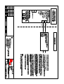
Fig 3 Using a single channel barrier.
If the beacon control switch is in the negative wire and the
power supply 0V is earthed, the circuit shown in Fig 4 may be
used. For simplicity the two barriers may be combined into
one package. The power supply voltage should be between
21V and the maximum working voltage of the 28V barrier.
a. Remove the beacon lens by unscrewing the two
captive screws and pull the lens away from the back
box.
b. Fit a suitable cable gland or conduit entry device that
will maintain the enclosure ingress protection in the
environmental conditions to which the unit is
subjected, into one of the holes in the enclosure.
Secure the back box to a vertical surface using the
6mm diameter holes in the two fixing lugs.
_______________________________________________________________________________________________________________________________
European Safety Systems Ltd. Impress House, Mansell Road, Acton, London W3 7QH
[email protected]
Tel: +44 (0)20 8743 8880
www.e2s.com
Fax: +44 (0)20 8740 4200
Document No. IS 4601
Issue E
27-11-09
Sheet 3 of 6