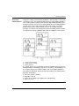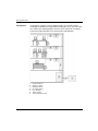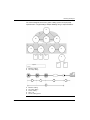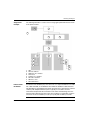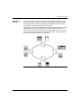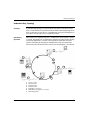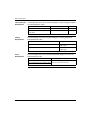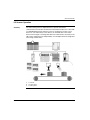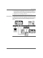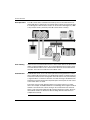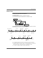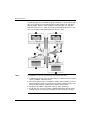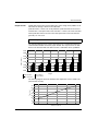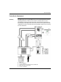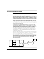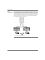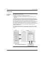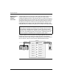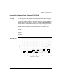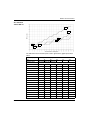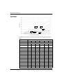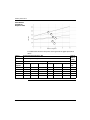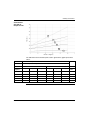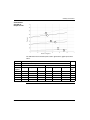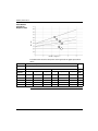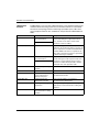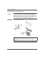
1
Transparent Ready
User Guide
31006929.01
8/2007
2
Table of Contents
Safety Information . . . . . . . . . . . . . . . . . . . . . . . . . . . . . . . . . . . . 9
About the Book . . . . . . . . . . . . . . . . . . . . . . . . . . . . . . . . . . . . . . 11
Chapter 1
Transparent Ready . . . . . . . . . . . . . . . . . . . . . . . . . . . . . . . . . . . 15
Transparent Ready . . . . . . . . . . . . . . . . . . . . . . . . . . . . . . . . . . . . . . . . . . . . . . .
Transparent Ready Service Classes Offered . . . . . . . . . . . . . . . . . . . . . . . . . . .
Users of this Guide . . . . . . . . . . . . . . . . . . . . . . . . . . . . . . . . . . . . . . . . . . . . . . .
How this Guide Is Organized. . . . . . . . . . . . . . . . . . . . . . . . . . . . . . . . . . . . . . . .
Chapter 2
2.1
2.2
2.3
2.4
16
19
23
24
Physical Planning, Design and Installation of a
Transparent Ready Industrial Ethernet Network . . . . . . . . . . . 27
Required Standards . . . . . . . . . . . . . . . . . . . . . . . . . . . . . . . . . . . . . . . . . . . . . .
On-going Industrial Ethernet Standardization Efforts . . . . . . . . . . . . . . . . . . . . .
Required Standards for Planning and Installation . . . . . . . . . . . . . . . . . . . . . . . .
Physical Planning and Layout . . . . . . . . . . . . . . . . . . . . . . . . . . . . . . . . . . . . . . .
Industrial Ethernet Cable Planning . . . . . . . . . . . . . . . . . . . . . . . . . . . . . . . . . . .
Structured Cabling Standards . . . . . . . . . . . . . . . . . . . . . . . . . . . . . . . . . . . . . . .
Cabling in a Transparent Ready Industrial Ethernet System . . . . . . . . . . . . . . .
Understanding Basic Network Structure . . . . . . . . . . . . . . . . . . . . . . . . . . . . . . .
Developing Network Architecture for Industrial Ethernet Networks. . . . . . . . . . .
Redundant Ring Topology. . . . . . . . . . . . . . . . . . . . . . . . . . . . . . . . . . . . . . . . . .
LAN Technologies and Network Design . . . . . . . . . . . . . . . . . . . . . . . . . . . . . . .
LAN Hardware. . . . . . . . . . . . . . . . . . . . . . . . . . . . . . . . . . . . . . . . . . . . . . . . . . .
Other LAN Considerations . . . . . . . . . . . . . . . . . . . . . . . . . . . . . . . . . . . . . . . . .
WAN Technologies and Network Design . . . . . . . . . . . . . . . . . . . . . . . . . . . . . .
WAN Hardware . . . . . . . . . . . . . . . . . . . . . . . . . . . . . . . . . . . . . . . . . . . . . . . . . .
Environmental Requirements . . . . . . . . . . . . . . . . . . . . . . . . . . . . . . . . . . . . . . .
Environmental Standards Summary . . . . . . . . . . . . . . . . . . . . . . . . . . . . . . . . . .
Mechanical Requirements. . . . . . . . . . . . . . . . . . . . . . . . . . . . . . . . . . . . . . . . . .
Climate Protection Requirements . . . . . . . . . . . . . . . . . . . . . . . . . . . . . . . . . . . .
Ingress Protection Requirement . . . . . . . . . . . . . . . . . . . . . . . . . . . . . . . . . . . . .
Electromagnetic Emission and Immunity Requirements . . . . . . . . . . . . . . . . . . .
Selection of Industrial Ethernet Components . . . . . . . . . . . . . . . . . . . . . . . . . . .
Ethernet Copper Cables . . . . . . . . . . . . . . . . . . . . . . . . . . . . . . . . . . . . . . . . . . .
28
29
32
34
35
36
40
43
49
53
55
59
61
62
65
67
68
69
71
73
76
77
78
3
2.5
2.6
2.7
4
Fiber Optic Cabling . . . . . . . . . . . . . . . . . . . . . . . . . . . . . . . . . . . . . . . . . . . . . . . 82
10/100BaseF Physical Layer Specification . . . . . . . . . . . . . . . . . . . . . . . . . . . . . 86
Ethernet Connectors for Copper Networks . . . . . . . . . . . . . . . . . . . . . . . . . . . . . 87
Fiber Optic Connectors . . . . . . . . . . . . . . . . . . . . . . . . . . . . . . . . . . . . . . . . . . . . 90
Recommended Infrastructure Devices for Industrial Ethernet . . . . . . . . . . . . . . . 92
Installation . . . . . . . . . . . . . . . . . . . . . . . . . . . . . . . . . . . . . . . . . . . . . . . . . . . . . . 93
EMC Installation Rules for Ethernet Networks. . . . . . . . . . . . . . . . . . . . . . . . . . . 94
Equipotential Bonding . . . . . . . . . . . . . . . . . . . . . . . . . . . . . . . . . . . . . . . . . . . . . 95
Equipotentially Bonding Your Building . . . . . . . . . . . . . . . . . . . . . . . . . . . . . . . . . 96
Local Equipotential Bonding of Equipment and Machines. . . . . . . . . . . . . . . . . . 98
EMC-compatible Ethernet Wiring and Cable Runs . . . . . . . . . . . . . . . . . . . . . . . 99
Ethernet Copper Cable Types . . . . . . . . . . . . . . . . . . . . . . . . . . . . . . . . . . . . . . 105
Ethernet Copper Cable Tools . . . . . . . . . . . . . . . . . . . . . . . . . . . . . . . . . . . . . . 108
How to Make an Ethernet Cable . . . . . . . . . . . . . . . . . . . . . . . . . . . . . . . . . . . . 109
Cabling Administration . . . . . . . . . . . . . . . . . . . . . . . . . . . . . . . . . . . . . . . . . . . . 111
Cabling Documentation . . . . . . . . . . . . . . . . . . . . . . . . . . . . . . . . . . . . . . . . . . . 112
Verification of a Transparent Ready Industrial Ethernet . . . . . . . . . . . . . . . . . . 114
Transparent Ready Industrial Ethernet Verification Recommendations . . . . . . 115
Permanent Links . . . . . . . . . . . . . . . . . . . . . . . . . . . . . . . . . . . . . . . . . . . . . . . . 116
Channels . . . . . . . . . . . . . . . . . . . . . . . . . . . . . . . . . . . . . . . . . . . . . . . . . . . . . . 118
Testing a Copper Installation . . . . . . . . . . . . . . . . . . . . . . . . . . . . . . . . . . . . . . . 120
Additional Considerations for Designing a Transparent Ready
Industrial Ethernet Network . . . . . . . . . . . . . . . . . . . . . . . . . . . . . . . . . . . . . . . . 121
Internet and IP Technologies in an Automation Environment . . . . . . . . . . . . . . 122
Open System Interconnection Model. . . . . . . . . . . . . . . . . . . . . . . . . . . . . . . . . 124
The TCP/IP Model . . . . . . . . . . . . . . . . . . . . . . . . . . . . . . . . . . . . . . . . . . . . . . . 125
Transparent Ready Model . . . . . . . . . . . . . . . . . . . . . . . . . . . . . . . . . . . . . . . . . 127
IP Addresses and Classes. . . . . . . . . . . . . . . . . . . . . . . . . . . . . . . . . . . . . . . . . 130
Multicasting Considerations . . . . . . . . . . . . . . . . . . . . . . . . . . . . . . . . . . . . . . . . 135
Multicast Filtering . . . . . . . . . . . . . . . . . . . . . . . . . . . . . . . . . . . . . . . . . . . . . . . . 136
Network Management . . . . . . . . . . . . . . . . . . . . . . . . . . . . . . . . . . . . . . . . . . . . 137
Routing. . . . . . . . . . . . . . . . . . . . . . . . . . . . . . . . . . . . . . . . . . . . . . . . . . . . . . . . 139
Introduction to Remote Access . . . . . . . . . . . . . . . . . . . . . . . . . . . . . . . . . . . . . 141
Remote Access Types . . . . . . . . . . . . . . . . . . . . . . . . . . . . . . . . . . . . . . . . . . . . 142
Network Access Methods . . . . . . . . . . . . . . . . . . . . . . . . . . . . . . . . . . . . . . . . . 144
PLC Connected to the Internet . . . . . . . . . . . . . . . . . . . . . . . . . . . . . . . . . . . . . 147
Security Issues. . . . . . . . . . . . . . . . . . . . . . . . . . . . . . . . . . . . . . . . . . . . . . . . . . 149
Chapter 3
Services Overview . . . . . . . . . . . . . . . . . . . . . . . . . . . . . . . . . . 153
3.1
Evaluating System Requirements . . . . . . . . . . . . . . . . . . . . . . . . . . . . . . . . . . . 154
Common Services at each Level in the Plant . . . . . . . . . . . . . . . . . . . . . . . . . . 155
Company Level Communication . . . . . . . . . . . . . . . . . . . . . . . . . . . . . . . . . . . . 156
Inter-PLC Level . . . . . . . . . . . . . . . . . . . . . . . . . . . . . . . . . . . . . . . . . . . . . . . . . 157
Field Level Communications . . . . . . . . . . . . . . . . . . . . . . . . . . . . . . . . . . . . . . . 157
Communication Service Selection . . . . . . . . . . . . . . . . . . . . . . . . . . . . . . . . . . . 158
Transparent Ready Support Services and Protocols. . . . . . . . . . . . . . . . . . . . . 161
3.2
3.3
3.4
3.5
3.6
3.7
3.8
3.9
3.10
3.11
I/O Scanning Service. . . . . . . . . . . . . . . . . . . . . . . . . . . . . . . . . . . . . . . . . . . . .
I/O Scanning Service Description . . . . . . . . . . . . . . . . . . . . . . . . . . . . . . . . . . .
I/O Scanner Operation . . . . . . . . . . . . . . . . . . . . . . . . . . . . . . . . . . . . . . . . . . .
Repetition Rates . . . . . . . . . . . . . . . . . . . . . . . . . . . . . . . . . . . . . . . . . . . . . . . .
Some Common Fault Conditions . . . . . . . . . . . . . . . . . . . . . . . . . . . . . . . . . . .
Response Times . . . . . . . . . . . . . . . . . . . . . . . . . . . . . . . . . . . . . . . . . . . . . . . .
Modbus Messaging . . . . . . . . . . . . . . . . . . . . . . . . . . . . . . . . . . . . . . . . . . . . . .
Modbus Messaging Service Description . . . . . . . . . . . . . . . . . . . . . . . . . . . . . .
Devices that Support Ethernet Modbus Services . . . . . . . . . . . . . . . . . . . . . . .
Modbus Client Operations in Quantum Systems . . . . . . . . . . . . . . . . . . . . . . .
Modbus Client Operations in Premium Systems. . . . . . . . . . . . . . . . . . . . . . . .
Modbus Client Operations in Momentum Systems . . . . . . . . . . . . . . . . . . . . . .
Modbus Server Operations in Quantum Systems . . . . . . . . . . . . . . . . . . . . . . .
Modbus Server Operations in Premium Systems . . . . . . . . . . . . . . . . . . . . . . .
Modbus Server Operations in Momentum Systems . . . . . . . . . . . . . . . . . . . . .
Modbus Servers and Socket Limits. . . . . . . . . . . . . . . . . . . . . . . . . . . . . . . . . .
Modbus Messaging Retry Times and Time-outs. . . . . . . . . . . . . . . . . . . . . . . .
Global Data Service . . . . . . . . . . . . . . . . . . . . . . . . . . . . . . . . . . . . . . . . . . . . .
Global Data Considerations . . . . . . . . . . . . . . . . . . . . . . . . . . . . . . . . . . . . . . .
Faulty Device Replacement . . . . . . . . . . . . . . . . . . . . . . . . . . . . . . . . . . . . . . .
Devices that Support the FDR Services . . . . . . . . . . . . . . . . . . . . . . . . . . . . . .
Time Synchronization . . . . . . . . . . . . . . . . . . . . . . . . . . . . . . . . . . . . . . . . . . . .
Time Synchronization Service. . . . . . . . . . . . . . . . . . . . . . . . . . . . . . . . . . . . . .
Time Synchronization Service Operation . . . . . . . . . . . . . . . . . . . . . . . . . . . . .
Time Synchronization Applications . . . . . . . . . . . . . . . . . . . . . . . . . . . . . . . . . .
Schneider Devices Implementing Time Synchronization Service . . . . . . . . . . .
Electronic Mail Notification Service . . . . . . . . . . . . . . . . . . . . . . . . . . . . . . . . . .
Electronic Mail Notification Service Operation . . . . . . . . . . . . . . . . . . . . . . . . .
Devices that Support Email Notification . . . . . . . . . . . . . . . . . . . . . . . . . . . . . .
Standard Web Server . . . . . . . . . . . . . . . . . . . . . . . . . . . . . . . . . . . . . . . . . . . .
Web Server Services. . . . . . . . . . . . . . . . . . . . . . . . . . . . . . . . . . . . . . . . . . . . .
Web Server Operation. . . . . . . . . . . . . . . . . . . . . . . . . . . . . . . . . . . . . . . . . . . .
Devices that Support Standard Web Server Services. . . . . . . . . . . . . . . . . . . .
FactoryCast Web Server . . . . . . . . . . . . . . . . . . . . . . . . . . . . . . . . . . . . . . . . . .
FactoryCast Web Server Operation . . . . . . . . . . . . . . . . . . . . . . . . . . . . . . . . .
Devices that Support FactoryCast Web Server Services . . . . . . . . . . . . . . . . .
FactoryCast HMI Web Server . . . . . . . . . . . . . . . . . . . . . . . . . . . . . . . . . . . . . .
FactoryCast HMI Web Services . . . . . . . . . . . . . . . . . . . . . . . . . . . . . . . . . . . .
Devices that Support The FactoryCast HMI Web Service . . . . . . . . . . . . . . . .
Other Services. . . . . . . . . . . . . . . . . . . . . . . . . . . . . . . . . . . . . . . . . . . . . . . . . .
FTP Service. . . . . . . . . . . . . . . . . . . . . . . . . . . . . . . . . . . . . . . . . . . . . . . . . . . .
SNMP Service . . . . . . . . . . . . . . . . . . . . . . . . . . . . . . . . . . . . . . . . . . . . . . . . . .
TFTP Service . . . . . . . . . . . . . . . . . . . . . . . . . . . . . . . . . . . . . . . . . . . . . . . . . .
Telnet Service . . . . . . . . . . . . . . . . . . . . . . . . . . . . . . . . . . . . . . . . . . . . . . . . . .
Quantum Device Support for Other Services . . . . . . . . . . . . . . . . . . . . . . . . . .
166
167
169
174
176
177
179
180
184
185
186
188
189
192
194
195
196
197
202
204
207
208
209
211
212
216
217
220
222
223
224
226
229
230
233
235
236
237
241
242
243
244
246
247
249
5
3.12
3.13
3.14
3.15
3.16
3.17
6
Other Services Supported by Premium Devices . . . . . . . . . . . . . . . . . . . . . . . . 251
Other Services Supported by TSX Micro Devices . . . . . . . . . . . . . . . . . . . . . . . 253
Other Services Supported by Momentum Devices . . . . . . . . . . . . . . . . . . . . . . 253
Other Services Supported by Advantys STB Devices . . . . . . . . . . . . . . . . . . . . 254
Other Services Supported by Power Logic Gateways/Bridges . . . . . . . . . . . . . 254
Other Services Supported by ConneXium Cabling Systems . . . . . . . . . . . . . . . 255
OPC Factory Server. . . . . . . . . . . . . . . . . . . . . . . . . . . . . . . . . . . . . . . . . . . . . . 256
OFS Services. . . . . . . . . . . . . . . . . . . . . . . . . . . . . . . . . . . . . . . . . . . . . . . . . . . 261
OFS Performance . . . . . . . . . . . . . . . . . . . . . . . . . . . . . . . . . . . . . . . . . . . . . . . 264
Runtime Architecture for Unity/OFS/SCADA: a Simple Example . . . . . . . . . . . 267
Build-time/Runtime Architecture for Unity/OFS/SCADA Systems that
Are Not Frequently Modified . . . . . . . . . . . . . . . . . . . . . . . . . . . . . . . . . . . . . . . 268
Build-time/Runtime Architecture for Unity/OFS/SCADA Systems that
Require Frequent Modification. . . . . . . . . . . . . . . . . . . . . . . . . . . . . . . . . . . . . . 270
Build-time/Runtime Architecture for a System with Multiple SCADA
Connections . . . . . . . . . . . . . . . . . . . . . . . . . . . . . . . . . . . . . . . . . . . . . . . . . . . . 272
SCADA/HMI . . . . . . . . . . . . . . . . . . . . . . . . . . . . . . . . . . . . . . . . . . . . . . . . . . . . 274
I/O Server to Field Device Communications . . . . . . . . . . . . . . . . . . . . . . . . . . . 277
SCADA Communications to Field Devices: Socket and Request Usage . . . . . 281
I/O Server and Display Client Communications. . . . . . . . . . . . . . . . . . . . . . . . . 285
Schneider Product Implementation Details . . . . . . . . . . . . . . . . . . . . . . . . . . . . 286
Redundancy. . . . . . . . . . . . . . . . . . . . . . . . . . . . . . . . . . . . . . . . . . . . . . . . . . . . 287
Network Redundancy and Communication Services. . . . . . . . . . . . . . . . . . . . . 288
Redundancy within a SCADA System . . . . . . . . . . . . . . . . . . . . . . . . . . . . . . . . 292
SCADA in a Quantum Hot-Standby System . . . . . . . . . . . . . . . . . . . . . . . . . . . 295
Hot Standby Swap and Ethernet Services. . . . . . . . . . . . . . . . . . . . . . . . . . . . . 302
Gateway/Bridge Systems. . . . . . . . . . . . . . . . . . . . . . . . . . . . . . . . . . . . . . . . . . 304
Gateway and Bridge Overview . . . . . . . . . . . . . . . . . . . . . . . . . . . . . . . . . . . . . 305
Gateway and Bridge Operation . . . . . . . . . . . . . . . . . . . . . . . . . . . . . . . . . . . . . 309
Supported Services per Device . . . . . . . . . . . . . . . . . . . . . . . . . . . . . . . . . . . . . 312
Ethernet Services and the Transparent Ready Devices that
Support Them . . . . . . . . . . . . . . . . . . . . . . . . . . . . . . . . . . . . . . . . . . . . . . . . . . 312
System Performance Evaluation . . . . . . . . . . . . . . . . . . . . . . . . . . . . . . . . . . . . 319
System Communications . . . . . . . . . . . . . . . . . . . . . . . . . . . . . . . . . . . . . . . . . . 320
Modbus Messaging Response Times . . . . . . . . . . . . . . . . . . . . . . . . . . . . . . . . 320
Modbus Server Response Times. . . . . . . . . . . . . . . . . . . . . . . . . . . . . . . . . . . . 321
Modbus Messaging Client Response Times . . . . . . . . . . . . . . . . . . . . . . . . . . . 325
I/O Scanner Systems . . . . . . . . . . . . . . . . . . . . . . . . . . . . . . . . . . . . . . . . . . . . . 329
Total Load on Devices . . . . . . . . . . . . . . . . . . . . . . . . . . . . . . . . . . . . . . . . . . . . 331
System Performance Solutions . . . . . . . . . . . . . . . . . . . . . . . . . . . . . . . . . . . . . 332
Gateway Response Times. . . . . . . . . . . . . . . . . . . . . . . . . . . . . . . . . . . . . . . . . 337
Chapter 4
Troubleshooting. . . . . . . . . . . . . . . . . . . . . . . . . . . . . . . . . . . . 341
4.1
About Troubleshooting. . . . . . . . . . . . . . . . . . . . . . . . . . . . . . . . . . . . . . . . . . . . 342
Introduction to Troubleshooting . . . . . . . . . . . . . . . . . . . . . . . . . . . . . . . . . . . . . 343
General Problem Identification. . . . . . . . . . . . . . . . . . . . . . . . . . . . . . . . . . . . . . 344
4.2
4.3
4.4
4.5
4.6
Appendices
Appendix A
A.1
A.2
Appendix B
Network Troubleshooting . . . . . . . . . . . . . . . . . . . . . . . . . . . . . . . . . . . . . . . . .
Introduction to Network Troubleshooting. . . . . . . . . . . . . . . . . . . . . . . . . . . . . .
Connection Troubleshooting . . . . . . . . . . . . . . . . . . . . . . . . . . . . . . . . . . . . . . .
Intermittent Connection Troubleshooting . . . . . . . . . . . . . . . . . . . . . . . . . . . . .
Slow Connection Troubleshooting. . . . . . . . . . . . . . . . . . . . . . . . . . . . . . . . . . .
Remote Access Troubleshooting . . . . . . . . . . . . . . . . . . . . . . . . . . . . . . . . . . .
Services Troubleshooting . . . . . . . . . . . . . . . . . . . . . . . . . . . . . . . . . . . . . . . . .
Modbus Messaging and I/O Scanner Troubleshooting . . . . . . . . . . . . . . . . . . .
SNMP Troubleshooting . . . . . . . . . . . . . . . . . . . . . . . . . . . . . . . . . . . . . . . . . . .
Telnet and FTP Troubleshooting. . . . . . . . . . . . . . . . . . . . . . . . . . . . . . . . . . . .
Faulty Device Replacement/BootP Troubleshooting. . . . . . . . . . . . . . . . . . . . .
SMTP Troubleshooting . . . . . . . . . . . . . . . . . . . . . . . . . . . . . . . . . . . . . . . . . . .
Time Synchronization (NTP) Troubleshooting Table . . . . . . . . . . . . . . . . . . . .
Web Troubleshooting Table . . . . . . . . . . . . . . . . . . . . . . . . . . . . . . . . . . . . . . .
SCADA/HMI System Slow Response Time Troubleshooting . . . . . . . . . . . . . .
Slow Response Time (SCADA/HMI) Troubleshooting . . . . . . . . . . . . . . . . . . .
Bridge Troubleshooting . . . . . . . . . . . . . . . . . . . . . . . . . . . . . . . . . . . . . . . . . . .
Lost Packet Troubleshooting. . . . . . . . . . . . . . . . . . . . . . . . . . . . . . . . . . . . . . .
Using a Packet Capture Tool . . . . . . . . . . . . . . . . . . . . . . . . . . . . . . . . . . . . . .
Packet Capture Troubleshooting. . . . . . . . . . . . . . . . . . . . . . . . . . . . . . . . . . . .
345
346
348
350
351
352
354
356
358
359
360
361
362
363
364
364
365
366
368
369
. . . . . . . . . . . . . . . . . . . . . . . . . . . . . . . . . . . . . . . . . . . . . 371
I/O Scanning Response Times . . . . . . . . . . . . . . . . . . . . . . . . 373
Premium PLC I/O Scanner Response Times . . . . . . . . . . . . . . . . . . . . . . . . . .
Premium I/O Scanner Response Times: Remote Input to Remote Output. . . .
Premium I/O Scanner Response Times: Remote Input to a Local Output . . . .
Premium I/O Scanner Response Times: PLC Memory to Remote Output . . . .
Quantum PLC I/O Scanner Response Times . . . . . . . . . . . . . . . . . . . . . . . . . .
Quantum I/O Scanner Response Tmes: Remote Input to Remote Output . . . .
Quantum I/O Scanner Response Tmes: Remote Input to Local Output . . . . . .
Quantum I/O Scanner Response Times: Local Input to Remote Output . . . . .
374
375
379
383
387
388
392
396
Modbus Server Throughput Capacity. . . . . . . . . . . . . . . . . . . 401
Quantum Modbus Server Throughput Capacity: Unity v2.0 . . . . . . . . . . . . . . . 402
Premium Modbus Server Throughput Capacity: Unity v2.0 . . . . . . . . . . . . . . . 404
Appendix C
Modbus Client Response Times . . . . . . . . . . . . . . . . . . . . . . . 405
Modbus Client Response Times: Premium TSXP575634M . . . . . . . . . . . . . . .
Modbus Client Response Times: Premium TSXP57304M . . . . . . . . . . . . . . . .
Modbus Client Response Times: Quantum 140 CPU65150 with an
Embedded Ethernet Port. . . . . . . . . . . . . . . . . . . . . . . . . . . . . . . . . . . . . . . . . .
Modbus Client Response Times: Quantum 140 CPU65150 with a
140 NOE77101 Ethernet Communications Module . . . . . . . . . . . . . . . . . . . . .
Modbus Client Response Times: Quantum 140 CPU65150 with a
140 NOE77111 Ethernet Communications Module . . . . . . . . . . . . . . . . . . . . .
406
413
420
425
430
7
Modbus Client Response Times: Quantum 140 CPU43412A with a
140 NOE77101 Ethernet Communications Module . . . . . . . . . . . . . . . . . . . . . . 435
Modbus Client Response Times: Quantum 140 CPU43412A with a
140 NOE77111 Ethernet Communications Module . . . . . . . . . . . . . . . . . . . . . . 440
Appendix D
Gateway Response Time and Timeout Measurements . . . . 445
D.1
EGX200 Gateway Serial Server Response Time and
Timeout Measurements . . . . . . . . . . . . . . . . . . . . . . . . . . . . . . . . . . . . . . . . . . . 446
EGX200 Serial Server Response Times . . . . . . . . . . . . . . . . . . . . . . . . . . . . . . 447
EGX200 Serial Server Response Measurements with
One Request Timeout . . . . . . . . . . . . . . . . . . . . . . . . . . . . . . . . . . . . . . . . . . . . 452
EGX400 Gateway Serial Server Response Time and
Timeout Measurements . . . . . . . . . . . . . . . . . . . . . . . . . . . . . . . . . . . . . . . . . . . 457
EGX400 Gateway Serial Server Response Times . . . . . . . . . . . . . . . . . . . . . . 458
EGX400 Serial Server Response Measurements with
One Request Timeout . . . . . . . . . . . . . . . . . . . . . . . . . . . . . . . . . . . . . . . . . . . . 463
174CEV30020 Gateway Serial Server Response Time and
Timeout Measurements . . . . . . . . . . . . . . . . . . . . . . . . . . . . . . . . . . . . . . . . . . . 468
174CEV30020 Gateway Serial Server Response Times. . . . . . . . . . . . . . . . . . 469
174CEV30020 Serial Server Response Measurements with
One Request Timeout . . . . . . . . . . . . . . . . . . . . . . . . . . . . . . . . . . . . . . . . . . . . 474
D.2
D.3
Appendix E
Standards and Other Considerations for
Industrial Ethernet Networks . . . . . . . . . . . . . . . . . . . . . . . . . 479
Standards and Organizations . . . . . . . . . . . . . . . . . . . . . . . . . . . . . . . . . . . . . . 480
Electromagnetic Compatibility . . . . . . . . . . . . . . . . . . . . . . . . . . . . . . . . . . . . . . 489
Copper Connector Standards Activities . . . . . . . . . . . . . . . . . . . . . . . . . . . . . . . 493
Conforming to Standards . . . . . . . . . . . . . . . . . . . . . . . . . . . . . . . . . . . . . . . . . 494
Transparent Ready Industrial Ethernet Conformance . . . . . . . . . . . . . . . . . . . . 496
Appendix F
Earthing (Grounding) Procedures . . . . . . . . . . . . . . . . . . . . . 499
Well-made Earthing (Ground) Connections . . . . . . . . . . . . . . . . . . . . . . . . . . . . 500
Making an Earthing Connection. . . . . . . . . . . . . . . . . . . . . . . . . . . . . . . . . . . . . 501
Cable Shielding Connection Options . . . . . . . . . . . . . . . . . . . . . . . . . . . . . . . . . 507
Copper Ethernet Testing Procedures . . . . . . . . . . . . . . . . . . . . . . . . . . . . . . . . 509
Performance Parameters. . . . . . . . . . . . . . . . . . . . . . . . . . . . . . . . . . . . . . . . . . 510
Definitions of Performance Parameters . . . . . . . . . . . . . . . . . . . . . . . . . . . . . . . 512
8
Glossary
. . . . . . . . . . . . . . . . . . . . . . . . . . . . . . . . . . . . . . . . . . . . . . 517
Index
. . . . . . . . . . . . . . . . . . . . . . . . . . . . . . . . . . . . . . . . . . . . . . 543
Safety Information
§
Important Information
NOTICE
Read these instructions carefully, and look at the equipment to become familiar with the
device before trying to install, operate, or maintain it. The following special messages
may appear throughout this documentation or on the equipment to warn of potential
hazards or to call attention to information that clarifies or simplifies a procedure.
The addition of this symbol to a Danger or Warning safety label indicates
that an electrical hazard exists, which will result in personal injury if the
instructions are not followed.
This is the safety alert symbol. It is used to alert you to potential personal
injury hazards. Obey all safety messages that follow this symbol to avoid
possible injury or death.
DANGER
DANGER indicates an imminently hazardous situation, which, if not avoided, will
result in death or serious injury.
WARNING
WARNING indicates a potentially hazardous situation, which, if not avoided, can result
in death, serious injury, or equipment damage.
CAUTION
CAUTION indicates a potentially hazardous situation, which, if not avoided, can result
in injury or equipment damage.
PLEASE NOTE
Electrical equipment should be installed, operated, serviced, and maintained only by
qualified personnel. No responsibility is assumed by Schneider Electric for any
consequences arising out of the use of this material.
© 2007 Schneider Electric. All Rights Reserved.
31006929 8/2007
9
Safety Information
10
31006929 8/2007
About the Book
At a Glance
Document Scope
This user guide deals with the broad topic of industrial Ethernet, a key element of
Schneider Electric’s Transparent Ready strategy. The purposes of the guide are
twofold:
z
z
to describe the impact of industrial Ethernet on new control system designs
to give you the information you need to implement and support a Transparent
Ready solution that best meets your application requirements
The guide describes four key parts of a successful system implementation:
z
z
z
z
planning a system for optimal performance
selecting the right Ethernet services and devices for your application
making the right choices as you design and install the system
troubleshooting system problems effectively
The guide is written for:
z
z
design engineers, system integrators and maintenance engineers who
understand industrial control systems and requirements but may not be familiar
with Ethernet products and services
plant IT staff who understand the principles of Ethernet system design and
installation but may not be familiar with industrial control requirements and
environments
Ethernet technology is well established in the business and commercial worlds, but
it is relatively new to the automation industry. Because it is an open technology,
Ethernet offers a wide range of products and services from multiple vendors. The
advantages of an open approach are clear; you are no longer subject to the
communication constraints, costs, and development schedules of a proprietary
vendor for your system needs.
However, some Ethernet components may not interoperate optimally in an industrial
environment, and not all Ethernet devices support all the services you may want. To
successfully design and troubleshoot an industrial Ethernet system, you need a mix
of Ethernet IT and traditional automation knowledge. This guide is designed to help
bridge the gap between these two disciplines.
31006929 8/2007
11
About the Book
The guide should be used as a supplement to product-specific Transparent Ready
user manuals. To learn more about commercially available Transparent Ready
products, refer to the latest Transparent Ready catalog or go to
www.telemecanique.com.
Validity Note
Related
Documents
The data and illustrations found in this book are not binding. We reserve the right to
modify Schneider Automation’s products in line with Schneider Automation’s policy
of continuous product development. The information in this document is subject to
change without notice and should not be construed as a commitment by Schneider
Electric.
Title of Documentation
Reference Number
ConneXium Ethernet Switch, 499NES25100 5-Port, 10/100 Base-TX 31005153
Quick Reference Guide
ConneXium Ethernet Switch, 499NES18100 8-Port, 10/100 Base-TX 31005416
Quick Reference Guide
ConneXium Ethernet Cabling System Switch Management Manual
31005844 (English)
31005845 (Français)
31005846 (Deutsch)
31005847 (Español)
ConneXium Ethernet Cabling System Quick Reference Guide
(Electrical Switch 10/100 Mbps 7TX 499NES17100/Optical Switch
10/100 Mbps 5TX/2FX 499NOS17100)
31005848 (English)
31005849 (Français)
31005850 (Deutsch)
31005851 (Español)
499NTR10100 ConneXium Transceiver Quick Reference Guide
Modicon Quantum Ethernet TCP/IP Module User Guide
840 USE 107
Modicon Quantum Ethernet Web Embedded Server User Guide
840 USE 115
Quantum 140 NOE 771 xx Ethernet Modules User Guide
840 USE 116
140NOE771xx/140NWM10000/140CPU651x0, Unity Pro 2.0 User
Guide
FactoryCast User’s Guide For Quantum, Premium and Micro
31001229
FactoryCast HMI, Premium and Quantum HMI Modules, Setup
Manual
35007415
Momentum 170ENT11001/170ENT11000 Ethernet Communication
Adapter User Guide
870 USE 114
174 CEV 200 30 Modicon TSX Momentum Modbus Plus to Ethernet 890 USE 151
Bridge User Guide
174 CEV 300 20 Mododbus to Ethernet Bridge User Guide
12
890 USE 195
31006929 8/2007
About the Book
Title of Documentation
Reference Number
Advantys STB Ethernet Modbus TCP/IP Network Interace
Applications Guide
890 USE 177
TSX Micro TSX ETZ 410/510 Modules User Manual
3500473404
Premium and AtriumUsing Unity Pro Ethernet Network Modules User 35006192
Manual
Ethernet Module Manuals for Unity
20110V20E
Altivar 58 Ethernet Modbus TCP/IP Communication Option
Instruction Bulletin
VVDED300053
Sepam series 80 functions - Introduction
EGX Installation Guide
63230-314-200B1
EGX User’s Guide
63230-208A1
EGX Reference Guide
63230-314-202A2
You can download these technical publications and other technical information from
our website at www.telemecanique.com.
Product Related
Warnings
Schneider Electric assumes no responsibility for any errors that may appear in this
document. If you have any suggestions for improvements or amendments or have
found errors in this publication, please notify us. No part of this document may be
reproduced in any form or by any means, electronic or mechanical, including
photocopying, without express written permission of the publisher, Schneider
Electric.
All pertinent state, regional and local safety regulations must be observed when
installing and using this product. For reasons of safety and to assure compliance
with documented system data, only the manufacturer should perform repairs to
components.
User Comments
31006929 8/2007
We welcome your comments about this document. You can reach us by e-mail at
[email protected]
13
About the Book
14
31006929 8/2007
Transparent Ready
1
At a Glance
Overview
This chapter introduces you to Transparent Ready, a major strategic program to
deploy Internet technologies in Schneider Electric products and services.
What's in this
Chapter?
This chapter contains the following topics:
Topic
Transparent Ready
31006929 8/2007
Page
16
Transparent Ready Service Classes Offered
19
Users of this Guide
23
How this Guide Is Organized
24
15
Transparent Ready
Transparent Ready
What Is
Transparent
Ready?
In 1996, Schneider Electric proposed a combination of technologies that
transformed industrial automation. This approach employed a combination of the
physical and data link layers of Ethernet, as defined by the OSI model (see p. 124),
with TCP/IP and Modbus for industrial Ethernet solutions. The concept, originally
known as Transparent Factory, has evolved to become the Transparent Ready
initiative.
Transparent Ready is a major strategic initiative that deploys Internet technologies
into Schneider Electric’s products and services. Any Schneider Electric product or
service that supports Internet technologies is a Transparent Ready product.
What Are Internet
Technologies?
Internet technologies describes a set of technological innovations that allow
information to be managed through the Internet and related hardware, software,
languages and protocols. They are used to transfer, present, and manage
information. Examples include:
z
z
z
What Is Industrial
Ethernet?
Ethernet (wireless, fiber optic, copper, and other) media through which
information is transferred
Ethernet frame, the Internet protocol suite (TCP/IP), SOAP, and other protocols
that transfer information
Java, HTML, XML, and other language protocols that present the information
Ethernet refers to the way that data accesses the network, how the messages are
framed for transmission and reception, and the physical characteristics of the
network: topology, cables, connectors and infrastructure.
Industrial Ethernet is the commercial name adopted by the industrial automation
market segment to refer to the use of Ethernet in an industrial environment. The term
is now so generic that other Internet technologies are included even if Ethernet itself
is not present. For example, Ethernet is not used in an industrial wireless 802.11
communication, but it is still considered an industrial Ethernet application.
A detailed analysis of industrial Ethernet (see p. 27) is presented in this manual, in
which the different characteristics and origins of Ethernet, TCP/IP and Modbus are
explained.
16
31006929 8/2007
Transparent Ready
Industrial and
Commercial
Ethernet
Comparison
In an industrial control environment, programmable logic controllers (PLCs) around
the plant act as servers for the input and output (I/O) modules. PLCs may be
interconnected by industrial fieldbuses, further distributing the data storage and
management responsibilities. A PLC may act as a server for some devices and as
a client for others:
The industrial network shown above is very different from a typical business and
commercial applications. Due to the critical nature of many control applications,
client devices throughout the industrial Ethernet system tend to be more intelligent
than standard commercial Ethernet clients. The ways in which the client and server
devices communicate with each other are defined by the Transparent Ready
services that they use.
A business Ethernet network is designed with a bank of servers residing in a control
room. Business data is stored and managed in this centralized area, and is sent to
and from the clients through switches and routers dispersed throughout the
enterprise. Firewalls secure the enterprise from unauthorized entry.
Industrial Ethernet is different from commercial Ethernet in three main areas:
environmental, layout, and performance requirements.
Environment
31006929 8/2007
Office Ethernet
Industrial Ethernet
Suitable for human
occupancy and work
Light-duty and heavy-duty industry
Normal temperature range
Potential harsh environments
Little dust, moisture, and
vibration
Exposure to electromagnetic noise
Hardly any mechanical
loads or problems with
chemicals
Extreme temperatures, climatic
variables
Low EMC requirements
Dust, moisture and vibration possible
17
Transparent Ready
Office Ethernet
Industrial Ethernet
Minimum pulling
requirements
Risk of mechanical damage or
problems with chemicals
Required grounding and bonding of
industrial equipment and cabling
Layout
Performance
Limited floor size in vertical
buildings
Large manufacturing areas in only
one floor
Star topology
Star, bus, and daisy chain topologies
may be used
In accordance with office
standards
Self-healing ring and redundant selfhealing ring to maximize up-time
High network availability
with reliable connections
High network availability (typically,
24X7 with redundancy)
Large data packets
Low bandwidth usage always
recommended (no higher than 40%
at all times)
Acceptable level of
predictability
Small data packets. Predictability is
essential
There are other areas of differentiation as well, such as the Ethernet services
required.
The Transparent
Ready Strategy
Transparent Ready offers a three-stage strategy:
1 Expose industrial control information via open or de facto standards
OPC and embedded Web server products open Schneider Automation devices
to several systems that can access information and knowledge buried in the
devices. Standard Web server technology allows any qualified personnel in the
enterprise to interact with the automation system.
2 Create interfaces and integration points between automation systems and
business applications
Using the device as a data server within a client/server architecture allows
Schneider alliances to develop interfaces to business systems in Windows or
UNIX environments.
3 Develop an open infrastructure that supports real-time and deterministic behavior
The network is the backbone for an efficient information exchange. Ethernet,
TCP/IP and Modbus are Schneider's primary choices for delivering an open
network. Switches and hubs help to build real-time and highly available
subnetworks and to address a broad range of applications.
18
31006929 8/2007
Transparent Ready
Transparent Ready Service Classes Offered
Summary
The Transparent Ready service classes make it possible to identify the services
provided by each product:
z
z
Diagnostic, display and control services via Web technologies
Ethernet communication services
Transparent Ready
Ethernet T CP/IP
techno lo gies and
services
Web Service
Classes
Web techn ologies
and services
Transparent Ready Web services are defined by 4 classes identified by letters:
z
z
z
z
Class A: no Web services
Class B: standard Web services
Class C: configurable Web services
Class D: active Web services
Transparent Ready products with an embedded Web server can provide 4 types of
Web service:
z
z
z
z
31006929 8/2007
maintenance Web services
control Web services
diagnostic Web services
optional Web services such as documentation or configuration
19
Transparent Ready
The following chart specifies the services provided by each Web service class:
Web Server
Class
Web Services
Maintenance
Monitoring and IT Link
Diagnostics
D
Active Web
Server
User Website
update
Autonomous execution of
specific services (e.g., alarm
notification by E-mail,
exchange with databases,
calculations)
SOAP/XML (client/server)
User-defined states User documentation
C
Configurable
Web Server
PLC variables editor
Remote commands
User Web pages
SOAP/XML (server)
Communication
service diagnostics
State of internal
product resources
B
Standard
Web Server
Remote device
Device description
software update
Data viewer
Remote auto-tests
A
No Web
Server
No Web services
Ethernet
Communication
Service Classes
Device diagnostics
Optional
Configuration of
network parameters
and Ethernet
communication
services
Device documentation
The Ethernet communication services provided by a product are defined in 3
classes. Each class is identified by a number:
z
z
z
Class 10: standard Ethernet communication services
Class 20: Ethernet communication management services (network level and
product level)
Class 30: advanced Ethernet communication services
Transparent Ready products can provide 8 types of Ethernet communication
services:
z
z
z
z
z
z
z
z
20
Modbus TCP messaging
I/O scanning
Faulty device replacement
Network management (SNMP)
Global data
Bandwidth management
Time synchronization (NTP)
Email event notification (SMTP)
31006929 8/2007
Transparent Ready
The following table specifies the services provided for each Ethernet communication
service class:
Service Ethernet Communication Services
Class
Modbus
I/O Scanning FDR
Messaging
30
Direct read/ Periodic read/
write of I/O write of I/O
Configuration
of the list of
devices
scanned
20
10
Read/Write
data words
31006929 8/2007
SNMP
Global
Data
SMTP
Bandwidth
NTP
Management
Automatic
control/
update of
device
parameter
configuration
Use of the
MIB library
by an
SNMP
manager
Publication and
subscription of
network
variables
Event
notification by
email
Monitoring of
local load
level
Automatic
assignment of
IP address
and network
parameters
Control/
update of
configuration
and product
parameters
by the user
Product
detection
of by an
SNMP
manager
Device
clock
synchronization
Local
assignment of
IP address
Verification of
duplicate IP
addresses
21
Transparent Ready
Choice of
Transparent
Ready Products
The services provided by a Transparent Ready product are identified by a letter
defining the level of Web service, followed by a number defining the level of Ethernet
communication service. For example:
z
z
A class A10 product is a product with no Web service and standard Ethernet
services.
A class C30 product is a product with a configurable Web server and advanced
Ethernet communication services.
The services provided by a higher class include all the services supported by a lower
class.
Transparent Ready products are chosen from 4 main families:
z
z
z
z
sensor and preactuator type field products (simple or intelligent)
controllers and PLCs
human-machine interface (HMI) applications
dedicated gateways and servers
The following selection chart can be used for choosing Transparent Ready products
according to the required service classes.
Web services
Class 30
C lass A
Class B
Class C
Class D
No se rvice
Stand ard
Con fi gura ble
Active
Adva nced
service
Ethernet
com municatio n
services
Class 10
22
Sta nda rd
service s
Class 20
C ommun icatio n
mana geme nt
servi ces
B30
C ontrol lers an d PLCs
B20
Simp le an d intel lig ent
pro ducts
A10
B 10
C20
D10
31006929 8/2007
Transparent Ready
Users of this Guide
Summary
To successfully design and troubleshoot an industrial Ethernet system, you need a
mix of Ethernet IT and traditional automation knowledge. A collaborative relationship
between the industrial control engineer and the plant IT professional is key to the
success of a Transparent Ready system.
Audiences
Analysis for this
Guide
This table describes the two audience groups for whom this guide is written, their
areas of expertise and their information needs. It also gives references to the
sections of this guide where the needed information can be found:
Audience
Expertise
Knowledge Needs
z TCP/IP protocol
IT
Professionals z Architectural alternatives,
such as Ethernet
switching
z Network security issues
z Hardware component
selection
z Open systems
z Standards interpretation
by different vendors
z Network component
selection
z Industrial plant environment and conditions
z Control device interaction
Industrial
Control
z Industrial installation
Professionals
requirements
z Data transfer speed
requirements
z Recovery and
redundancy needs
z Ethernet technology requirements
z Network shielding from noise and
interference
z Physical network implementation in an
industrial setting
z Operational priorities: redundancy, quick
recovery
z Safety issues associated with the failure of
automation controls
z Transparent Ready service selection
Transparent Ready services (see p. 153)
z Open system environment requirements
z Open system communications issues
z Integration of products from multiple
vendors
z System design and protocols
z System security issues
31006929 8/2007
23
Transparent Ready
How this Guide Is Organized
Summary
A Transparent Ready system comprises two key elements:
z
z
the Ethernet network over which the devices exchange application data
the services that enable the transactions that happen on the network
The three chapters that follow contain stand-alone discussions of the major topics
you will need to consider as you design a new Transparent Ready system or
maintain an existing system. The chapters may be read in any order, based on the
topics that interest you the most.
Physical
Planning, Design
and Installation
Physical Planning, Design and Installation of a Transparent Ready Industrial
Ethernet Network, p. 27 describes how to design, install and verify your Transparent
Ready industrial Ethernet network to best meet your application requirements,
including the following considerations:
z
z
z
z
z
z
z
z
z
Transparent
Ready Services
design standards
choice of cabling and components
Internet technology overview
environmental requirements
protective earthing recommendations
testing your network
IP Addressing
routing
security
Services Overview, p. 153 describes each of the Transparent Ready services, the
appropriate device choices for each, and the Transparent Ready devices that
support each service. Service support is a very important device selection criterion.
Choosing the right services enables you to account for the following system design
issues:
z
z
z
appropriate device response times
avoidance of device overload
application throughput requirements for the entire system
This chapter also explains how the different services operate and their expected
performance.
24
31006929 8/2007
Transparent Ready
Troubleshooting
Troubleshooting, p. 341 provides procedures for how to maintain a Transparent
Ready system after installation. These procedures include how to:
z
z
z
Supporting
Information
31006929 8/2007
identify problems such as
z network infrastructure issues
z device incompatibility
z performance issues
z environmental interference
identify sources by:
z device query and response times
z device incompatibility
identify resolutions such as:
z device replacement
z system redesign
z work-arounds for an unfixable problem
A set of appendixes containing the results of performance measurements is
presented at the end of the guide. The results compare the response times and
throughput rates of different Transparent Ready devices that use some of the key
network services. There is also a detailed section on Standards.
25
Transparent Ready
26
31006929 8/2007
Physical Planning, Design and
Installation of a Transparent
Ready Industrial Ethernet Network
2
At a Glance
Overview
This chapter discusses the topics concerning Ethernet that an automation or control
engineer should consider when planning, installing, and verifying a Transparent
Ready industrial Ethernet network.
In designing a Transparent Ready industrial Ethernet network to fit your facility, you
should have a general knowledge of network layout, criteria for choosing
components, issues pertinent to the design process and the existing standards for
office network components and layout that guide industrial network development.
You may consult your IT personnel or a variety of written and electronic sources for
more detailed information.
The planning section provides a description of network topologies, an overview of
applicable standards for offices and plants, overall design considerations, and
recommendations for selecting components.
The installation section describes EMC installation and the installation of cables and
connectors.
The section on verification discusses methods for your network.
What's in this
Chapter?
This chapter contains the following sections:
Section
2.1
31006929 8/2007
Topic
Required Standards
Page
28
2.2
Physical Planning and Layout
34
2.3
Environmental Requirements
67
2.4
Selection of Industrial Ethernet Components
77
2.5
Installation
93
2.6
Verification of a Transparent Ready Industrial Ethernet
114
2.7
Additional Considerations for Designing a Transparent Ready
Industrial Ethernet Network
121
27
Planning and Layout
2.1
Required Standards
At a Glance
Overview
Office-based Ethernet standards are being enhanced and modified to meet
industrial Ethernet requirements. These Ethernet standards are being combined
with industrial standards to account for the environment in which an industrial
Ethernet must operate and its performance and topology requirements.
Many standards are used to define industrial Ethernet. These standards are
developed and maintained by different standards organizations and are related to
the following:
z
z
z
z
z
protocols
the physical layer
environmental requirements
cabling structures
cable specifications
Many of these standards are regional and may apply only to specific areas or
countries.
What's in this
Section?
28
This section contains the following topics:
Topic
Page
On-going Industrial Ethernet Standardization Efforts
29
Required Standards for Planning and Installation
32
31006929 8/2007
Planning and Layout
On-going Industrial Ethernet Standardization Efforts
Introduction
There are as yet no industrial Ethernet planning standards to refer to for guidelines
and rules. There are, however, many recommendations for industry, based on the
office environment standards (TIA/EIA-568-B, ISO/IEC-11801, and EN 50173), that
have been placed before standards committees by several industrial networking
organizations.
The most significant international standardization effort is by a collaborative group
of experts from IEC TC65, TIA TR-42.9, and CENELEC TC215 WG1. Their work will
be published as the ISO/IEC 24702 standard.
TIA TR-42.9
ISO/IEC 24702
Standard: Time
Table and
Definitions
CLC TC215 WG1 PTP
ISO/IEC JTC1SC26 IFTG
Publication of the ISO/IEC 24702 standard is planned for sometime in 2006.
The ISO/IEC 24702 standard defines generic cabling for industrial premises and
related IT specifications. For its definition of balanced cabling and optical fiber, it
takes the following from ISO/IEC 11801:
z
z
z
applications
link and channel transmission classes
transmission performance components
It also adds new concepts such as the classification environment (as presented
below in the MICE table), suitable components, and a modified cabling structure.
31006929 8/2007
29
Planning and Layout
MICE Concept
Mechanical
Rating
The IEC TC65C working group originated the MICE concept of mechanical rating to
define environmental parameters and their requirements. MICE includes three
environmental classes:
z
z
z
Class 1: for general (non-industrial/non-residential)
Class 2: for light industrial
Class 3: for heavy industrial
It also defines the environmental parameters on which its name is based:
z
z
z
z
mechanical
ingress
climatic
electromagnetic
Each environmental parameter has a low-level (1), medium-level (2), and high-level
(3) rating that is indicated in subscript beside each parameter's letter, for example
M2I2C3E. As you can see from this example, parameter levels may be mixed and
may vary along a single channel.
Each environmental class has a worst case scenario as given below:
z
z
z
M1I1C1E1: for a general (ISO/IEC 11801) environment
M2I2C2E2: for a light industrial environment
M3I3C3E3: for a heavy industrial environment
The MICE table is shown below:
---> Increasing Severity --->
Class
Mechanical
Shock/Bump
M1
M2
M3
I1
I2
I3
C1
C2
C3
Vibration
Tensile Force
Crush
Impact
Ingress
Particulate
Immersion
Climatic
Temperature
Ambient
Rate of Change
Humidity
UV Radiation
Solar Radiation
Liquid Pollution
Gaseous Pollution
30
31006929 8/2007
Planning and Layout
---> Increasing Severity --->
Class
Electromagnetic
ESD
E1
E2
E3
Radiated RF
Conducted RF
EFT
Surge
Magnetic Field
ISO/IEC 24702:
Unification of
Major Standards
Committees
To avoid different proprietary developments, the Customer Premises Cabling
working group (ISO/IEC JTC 1 SC 25 WG3) was created. This group in turn
launched the Industrial Premises Task Group (ISO/IEC JTC 1 SC 25 WG3.IPTG).
To achieve maximum cooperation and expedite the development of an international
standard, the Industrial Premises group has directly involved experts from the major
standards organization committees (IEC TC65C, TIA TR42.9, and CENELEC
TC215 WG1). The purpose of this new group is to standardize the characteristics of
cabling systems for industrial facilities. The standard will be published as ISO/IEC
24702.
The Industrial Premises Task Group is jointly led by ISO/IEC JTC 1/SC 25 and IEC
SC 65C.
z
z
The JTC 1/SC 25 subcommittee is responsible for cabling for building sites.
The IEC SC 65C subcommittee is responsible for cabling for process control. The
IEC SC 65C is a subcommittee of the IEC TC65C in charge of developing
standards for industrial networks.
Due to the fact that the ISO/IEC 24702 standard is currently being developed,
Schneider Electric suggests that you follow the guidelines that are defined in this
chapter.
31006929 8/2007
31
Planning and Layout
Required Standards for Planning and Installation
Ethernet
Standards
The Ethernet standard to consider when you plan an industrial Ethernet network is
the one defined by the IEEE and adopted by ISO/IEC:
IT Structured
Cabling
Standards
IEEE standard 802.3, 2002 Edition, Part 3: Carrier sense multiple
access with collision detection (CSMA/CD) access method and
physical layer specifications.
IEEE 802.3
Information Technology. Telecommunication and Information
exchange between systems. Part 3: Carrier sense multiple access
with collision detection (CSMA/CD
ISO/IEC 8802-3
Cable manufacturers, suppliers, building designers, network architects, and service
technicians all rely on cable standards to provide the specifications for their projects.
These specifications include all aspects of the planning, design, and installation
phases, as well as the configuration, performance, conformance testing, and
verification of the final system.
The three major world standards shown in the table below are the foundations for
cabling planning, selection, installation, and performance of IT networks. Each
standard in the table is based on the one that precedes it. As a result, all of the
standards are very similar.
Area and Standard
Standards Organizations Description
United States
Telecommunications
Industry Association
TIA/EIA-568-B
Electronic Industries
Association
International
Europe
32
ISO/IEC 11801
CENELEC EN 50173
International Organization
for Standardization
Commercial Building Telecommunication
Cabling standard - defines how to design,
build, and manage a structured wiring
system.
International Engineering
Consortium
Generic Customer Premises Cabling
standard - defines general cabling
specifications for customer premises; based
on TIA/EIA-568.
Comité Européen de
Normalisation
Electrotechnique
Defines generic cabling and European
open-market cabling components; based on
ISO 11801.
31006929 8/2007
Planning and Layout
Environmental
Standards
Environmental standards are not specifically related to industrial Ethernet, but apply
to any device or equipment located in the particular environment.
Schneider Electric has defined three types of environments that coincide with the
MICE table:
z
z
z
office environment, where standard Ethernet can be used
light industrial environment
heavy industrial environment
The environmental requirements for industrial Ethernet are defined by the same
specifications that cover other industrial automation devices (see p. 67).
31006929 8/2007
33
Planning and Layout
2.2
Physical Planning and Layout
At A Glance
Overview
This section presents cabling standards for an industrial Ethernet network. It also
describes layouts for a Transparent Ready industrial network. To assist in
understanding this structure, basic network topologies are reviewed. LAN
technologies and issues relevant to an industrial Ethernet network are discussed, as
are WAN technologies and hardware.
What's in this
Section?
This section contains the following topics:
34
Topic
Page
Industrial Ethernet Cable Planning
35
Structured Cabling Standards
36
Cabling in a Transparent Ready Industrial Ethernet System
40
Understanding Basic Network Structure
43
Developing Network Architecture for Industrial Ethernet Networks
49
Redundant Ring Topology
53
LAN Technologies and Network Design
55
LAN Hardware
59
Other LAN Considerations
61
WAN Technologies and Network Design
62
WAN Hardware
65
31006929 8/2007
Planning and Layout
Industrial Ethernet Cable Planning
Introduction
Because there are as yet no defined standards for the physical layout of an industrial
Ethernet network, Schneider Electric has chosen to conform to the recommendations submitted by standards organizations such as Modbus-IDA, IAONA, PNO,
and the work in progress by the IEC.
An industrial manufacturing site is a physical facility in which manufacturing or
process control activities take place. In most cases, the site consists of multiple
buildings or plants that manage interconnected, but separate, processes. The
physical layout and environmental variables inherent in each of these facilities may
result in different requirements for the cabling system at each site. This section
describes Schneider Electric’s recommendations for planning industrial Ethernet
networks for manufacturing and process control environments.
Cable Planning
A network site plan communicates the physical and logical layout of a network that
is specific to your site requirements. This plan is an important part of the network
design process for your facility. The site may be an industrial facility or an
infrastructure site. Infrastructure sites include environments, such as tunnels, water
treatment plants and airports, with additional requirements to those of an industrial
site. Both types of site have environmental variables that may be extreme compared
to office environments. The existing standards for office environments, though
useful and valid, have limited application in such environments. Application
performance under rigorous environmental requirements, including climatic
conditions and ingress protection, has a higher priority in an industrial environment.
The following topics provide general information on planning an industrial Ethernet
network for industrial and infrastructure applications. This information does not
attempt to cover every possible variation of these two environments. You should
adapt this information to the specific needs of your site.
31006929 8/2007
35
Planning and Layout
Structured Cabling Standards
Introduction
Schneider Electric recommends the use of structured cabling standards including
TIAEIA 568B, ISO/IEC 11801 and CENELEC EN 50173 (see p. 32). Standards for
cabling are currently being developed by a working group of the standards
organizations.
Elements of a
Cabling System
The table below shows the elements of a cabling system as defined by the ISO/IEC
11801 standard. This standard also identifies the interfaces through which different
network components are connected to the cabling system.
Elements
(Hierarchical Order)
Abbreviation Purpose
Campus Distributor
CD
Campus Backbone Cable
Building Distributor
cabling between buildings that share
telecommunications facilities
BD
Building Backbone Cable
Floor Distributor
connects the horizontal cable system to other
cabling subsystems
cabling between and including the
telecommunications outlet and the horizontal
distributor
Transition Point (optional)
TP
location in horizontal cabling subsystem where
flat undercarpet cabling connects to round
cabling
Telecommunications Outlet
TO
female telecommunications device found in the
work area
For a cabling installation to conform to the ISO/IEC-11801 standard, the
configuration must connect the following subsystems of a cabling system:
z
z
z
36
the distributor where the bldg. backbone cable
terminates, connections to campus backbone
cable are made
intermediate cable & connecting hardware
FD
Horizontal Cable
Cabling
Subsystems
distributor from which the campus backbone
cable emanates
campus backbone; campus uses building distributors
building backbone; every building has a building distributor
horizontal cabling; every floor has a floor distributor
31006929 8/2007
Planning and Layout
Structure of
Cabling Systems
The generic cabling system defined by the ISO/IEC 11801 standard is a hierarchical
star structure (see p. 44). The diagram below shows a central campus distributor
and a campus backbone cabling system linking multiple building distributors. Each
building is required to have at least one building distributor. Each building distributor
connects to the central campus distributor using a star topology. The campus
distributor becomes the central communication unit. As a backup and safety
precaution, you should create redundant links between buildings. Within a building,
every floor has its own floor distributor that serves up to 2000 m2 of office space.
1
2
3
Central campus distributor
Campus backbone cabling
Building distributor
In a campus that has only one building, the primary distribution point becomes the
building distributor in that building. However, it is possible for a large building to act
as a campus and have one campus backbone with several building distributors.
The number of subsystems and type of elements included in your implementation
depend on the following:
z
z
z
z
31006929 8/2007
size of the campus or building
geography of the site
purpose of the cabling system (applications and equipment)
types of end user
37
Planning and Layout
Configuration
It is possible to configure a generic cabling system to your specific needs by
rearranging the distributors to support different topologies (see p. 43), such as bus,
star, and ring. The following diagram shows the linear connections of a cabling
system from campus distributor to the terminal outlet and equipment.
1
2
3
4
5
6
7
38
Campus distributor
Backbone cabling
Building distributor
Secondary cabling
Floor distributor
Tertiary cabling
Telecommunication outlet
31006929 8/2007
Planning and Layout
The next two diagrams show how a generic cabling system can be physically
implemented in a single building or multiple buildings along a campus backbone.
CD
BD
FD
FD
FD
TO
BD
BD
TO
FD
TO
TP
TO
TO
Optional
2
4
Backbone cabling
Secondary cabling
2
6
4
8
9
2
4
6
8
9
31006929 8/2007
Backbone cabling
Secondary cabling
Tertiary cabling
Patch cord
Generic cabling system
39
Planning and Layout
Cabling in a Transparent Ready Industrial Ethernet System
Introduction
Multiple Plant
Site Example
The Transparent Ready approach to planning a cabling system is similar to that of
industrial Ethernet organizations such as Modbus-IDA, based on the accepted ISO/
IEC 11801, EN 501731, and TIA/EIA 568B standards.
The following diagram shows a cabling system with the following parameters:
z
an industrial site distributor that acts as the central communication unit instead of
a campus distributor (see p. 36) and connects plant distributors along an
industrial site backbone
z
plant distributors that connect office plant and plant floor distributors along a plant
backbone
z
plant floor distributors that connect to cabinet distributors (CD, also called
machine or field distributors, FD) and the devices and device outlets (DO) inside
the cabinet
z
office plant distributors that connect to telecommunications outlets that are
themselves connected to printers and computers
It is important to understand that a site may have many plants within it. The following
example shows an overview of a grain site with 6 plants.
Industrial Site
Administration Office
2
3
Port Plant
5
1
Shipping
Plant
4
Mill/Crushing Plant
Oil Extraction Plant
Mixing Plant
1
2
3
4
5
40
Silo Plant
SD Site distributor
PD Plant distributor
POD Plant office distributor
PFD Plant floor distributor
FW Firewall
31006929 8/2007
Planning and Layout
SIngle Plant
Example
The following illustration is a closer view of a single grain plant within the site shown
in the previous figure.
1
4
4
2
2
4
5
6
6
6
7
7
7
7
8
7
7
1
2
3
4
5
6
7
8
Industrial Site
Distributor
31006929 8/2007
SD Site distributor
PD Plant distributor
POD Plant office distributor
FW Firewall
PFD Plant floor distributor
CD Cabinet distributor
DO Device outlet
FD Field distributor
An industrial site distributor plays the same role as a campus distributor in the ISO/
IEC 11801 standard, as the distributor from which the backbone cable emanates.
This distributor is managed by IT personnel and can be one or more devices (racked
switches) with multiple numbers of ports. Typically, it is located in an office
environment and provides the connection for the entire manufacturing site to the
Internet and to other physical sites in the same company or organization. Traffic in
and out of the site is isolated by a router (see p. 65) and secured by a firewall.
41
Planning and Layout
Industrial Site
Backbone
The industrial site backbone is the cabling system that extends from the industrial
site distributor to the plant distributors. Typically, the industrial site is a self-healing
ring (see p. 51) that can be made redundant with a dual self-healing ring (see p. 53).
Plant Distributor
The plant distributor connects the industrial site backbone to a plant. It acts as a
building distributor. Most industrial sites consist of one or more separate plants.
These different plants may have control rooms from which the plant is operated, or
motor control centers where the MCC and control devices are located. Typically, the
plant distributor is located in either the control or MCC room. The environmental
requirement for a plant distributor is either office or light-industrial.
Office Plant
Distributor and
Plant Floor
Distributor
As mentioned previously, the plant distributor is usually located either in the control
or MCC room; the plant distributor is connected to the other distributors, such as the
office plant distributor and the plant floor distributor. The office plant distributor
manages the terminal outlets for the plant office. These terminals are used to
connect printers, computers, and video conferencing devices. The plant floor
distributor manages equipment on the plant floor. In most cases, these two
distributors are located in either an office or a light-industrial environment. The office
plant distributor is usually managed and maintained by IT personnel. The plant floor
distributor is managed by personnel responsible for the cabinet distributors (also
called field distributors or machine distributors). The traffic between the plant floor
distributor and the plant distributor is isolated with a router and secured with a
firewall.
Cabinet, Field,
and Machine
Distributors
Typically, cabinets contain devices with a low number of ports or connections, such
as switches. Cabinet distributors (also called field distributors or machine
distributors) provide connectivity to the devices located inside a cabinet, in a
machine, or on the plant floor.
The following table shows the environmental requirements based on the location of
the devices.
Device Location
Environmental Requirement
Inside a cabinet
Light industrial environment
In a machine
Light or heavy industrial environment
On plant floor
Heavy industrial environment
Inside the cabinets, the configuration is star or daisy chain (using devices with
two Ethernet ports). The next topic (see p. 43) presents some typical network
topologies and how they can be developed in an Ethernet environment.
These topologies are usually deployed beginning with the plant floor distributor.
Device outlets (DOs) are located inside the cabinet. If the devices are located on the
plant floor, there can be either a DO or a new distributor for devices in the field
(called a field distributor or FD).
42
31006929 8/2007
Planning and Layout
Understanding Basic Network Structure
Summary
The physical layout, or topology, of a network consisting of cables, components and
devices can be structured in any of several architectures:
z
z
z
z
z
z
bus
star
daisy chain
ring
dual ring
mesh
Illustrations of each type of layout are included. Each layout has its advantages and
disadvantages, as shown in the tables. Switches and hubs are mentioned in
conjunction with the network architecture. Schneider Electric recommendations for
network layout are also discussed.
Bus Topology
A bus topology has a similar layout to a more traditional automation network such
as the Modbus Plus. A single backbone cable connects all the devices on the
network. Terminators are placed at each end of the backbone to allow signals to be
sent and cleared over the network. Devices, usually connected using T-connectors,
can be installed anywhere along the bus.
1
1
2
1
2
3
3
terminator
backbone
T-connector
A section of backbone cable is known as a segment. Several segments can be
connected using bridges or repeaters, as shown in the illustration below.
1
2
3
1
2
3
31006929 8/2007
Segment 1
Repeater
Segment 2
43
Planning and Layout
Only one device at a time can send or transmit a packet of information. The packet
travels the entire bus backbone cable. For this reason, a bus topology is considered
a shared medium. Terminators are very important because a cable break can result
in all devices losing their ability to communicate.
Star Topology
Advantages
Disadvantages
Low cost.
Scalability is a problem; it is difficult to change
the network as your needs change. As traffic
and the number of devices increase, the
performance of the network decreases.
Easy installation; all network devices are
connected to a cable segment, and you
need only enough cable to connect the
equipment that you have.
The devices are usually connected using taps
into the trunk cable. If a device or segment is
lost, all the devices further down the line could
become unavailable.
The backbone follows the a path around the
plant much like a proprietary automation
network, making the network design easy to
understand for designers new to Ethernetin-automation applications.
Because all the devices share the same
backbone cable, the throughput is limited; only
one device can communicate at any time.
In a star topology, all the devices are connected though a central device. A star
topology is a common network layout for office environments and also for newer
automation environments.
star
44
The speed of all devices on a bus network must
be the same.
star
31006929 8/2007
Planning and Layout
In a star topology, devices can use dedicated sections of the network for various
services.
Advantages
Disadvantages
Network throughput is much higher than on a sharedmedia bus topology.
Star topologies are more costly
because a dedicated cable must
be run to each device.
Network reconfiguration is much easier.
To offset this disadvantage,
Centralizing network components makes administration
network infrastructure
easier; centralized management and monitoring of
components (switches, hubs, etc.)
network traffic enhances network performance.
are used in cabinets on the factory
Diagnostics are simple; if a network segment fails, it
floor so that a group of local
affects only the devices directly connected to that
devices can be connected
segment.
together. A single long cable can
Infrastructure components use monitoring software and be run back to a central point to
support the group, rather than
device-based LEDs to indicate failures; most single
points of failures can be diagnosed and repaired quickly. using separate cables for each
device.
Resilience; a cable failure takes only that device out of
service.
You can have more devices on a single network than on
a bus topology.
Daisy Chain
Topology
In daisy chain topology, the device is part of the trunk cable, unlike in bus topology
where the device is connected to the cable through a tap connector and is not
considered part of the trunk cable. Every device in a daisy chain has two network
ports; information flows through the device. Although a daisy chain is linear, there
are branching devices available that allow the development of more complex
topologies.
The Interbus is an example of as daisy chain network.
Advantages
Disadvantages
Low cost; there is no In a linear configuration, if a device fails, the network gets cut.
need to consider
If not properly designed, the devices in a daisy chain may become
Tap connectors.
overloaded trying to manage the information flowing through them.
Potential network overload; all devices share the same trunk cable.
31006929 8/2007
45
Planning and Layout
Ring Topology
In a ring topology, all devices or network infrastructure components are connected
in a loop with no beginning or end. Packets travel in a single direction on the ring as
they are passed from one device to the next. Each device checks a packet for its
destination and passes it on to the next device.
Ring topologies provide redundancy. The failure of a single link is handled by routing
traffic in the opposite direction. A ring may be based on token rotation or random/
shared access. Alternatively, it may be a switched network where all the devices
access the network at the same time at different speeds.
46
Advantages
Disadvantages
Redundancy; the failure of a single link
or infrastructure component does not
affect the entire network.
High cost; more cabling is needed to complete the
ring.
A ring topology uses software to
monitor the network links.
Network infrastructure components need
intelligence to respond to device failures; they are
more costly than simple bus or star components.
31006929 8/2007
Planning and Layout
Dual Ring
Topology
When industrial automation systems are used in critical applications where
downtime is unacceptable, a dual ring topology may be deployed.
A dual ring has all the features of a single ring with more fault tolerance. It comprises
infrastructure components connected together with multiple rings. Each device is
connected to two infrastructure components. Each infrastructure component is
connected to a separate ring. When a single link or infrastructure device fails, all
other devices can still communicate.
Dual ring topologies used in automation environments have additional features not
always found in typical data communications environments. For example, hot
standby links are used between rings. When a link fails, the standby becomes active
and prevents any interruption in network communications. Watchdog packets are
sent out to inactive connections and they create logs if the connection remains
inactive. The watchdog packets create log entries that are monitored by the network
administrator.
Advantages
Disadvantages
Redundancy; the failure of multiple devices or
cables does not cause the network to fail.
Cost, compared to a single ring, since
the amount of equipment is doubled.
Separate power supplies can be used for each ring. The need to regularly monitor unused
Multiple interfaces within a device can connect the links so that they are known to be
device to different rings so that the flooding of one healthy in the event that they are
needed.
ring with collisions or broadcast traffic does not
cause the system to fail.
31006929 8/2007
47
Planning and Layout
Mesh Topology
A mesh topology is used in very large networks or network backbones where every
end device or infrastructure device has a connection to one or more components of
the network. Ideally, each device is directly connected to every other device in the
mesh.
Another mesh implementation is as a network backbone that connects separate star
structures. This combined topology provides fault tolerance to the backbone without
the high cost of a mesh topology throughout the entire network.
Star
Mesh
Mesh topologies are used less frequently because of cost and complexity.
48
Advantages
Disadvantages
Fault tolerance; if a break occurs
anywhere in the network cable segment,
traffic can be rerouted.
Complexity; difficult to manage and administer.
High cost; more cabling and interfaces are
needed to support the redundant connections.
31006929 8/2007
Planning and Layout
Developing Network Architecture for Industrial Ethernet Networks
Introduction
Along with a basic understanding of network architecture (topologies) and Ethernet
for office environments, there are some further considerations when deploying
Ethernet in a plant environment. The various topologies and their application in an
automation plant layout are discussed, with suggestions for appropriate hardware.
Ethernet Bus
Topology
An Ethernet bus can be deployed by interconnecting hubs and/or switches in line
and considering each one of them as the connection for a device. A limited number
of hubs and an unlimited number of switches can be interconnected to achieve this
purpose.
1
1
2
1
2
31006929 8/2007
1
2
2
1
2
Ethernet switches
Ethernet devices
49
Planning and Layout
Ethernet Star
Topology
In an Ethernet star, the intermediate device may be a hub or a switch. A star is the
most commonly used topology in office networks and has been adopted in most
automation applications. For industrial Ethernet applications, the use of a full duplex
switch as the central device, rather than a hub, is strongly recommended.
2
1
1
2
2
1
2
Ethernet Daisy
Chain Topology
50
Ethernet switches
Ethernet devices
To develop an Ethernet daisy chain network, devices with dual Ethernet ports are
required. Schneider Electric is releasing industrial Ethernet devices with this type of
functionality (dual Ethernet ports for daisy chain connectivity) at the present time.
31006929 8/2007
Planning and Layout
Ethernet Ring
Topology
Ethernet rings usually form the backbone for high-availability applications. Two
paths are available to reach the same device. If ring topology is required, switches
that support either a proprietary ring topology or spanning tree protocol (either
spanning tree or rapid spanning tree) need to be used.
Spanning tree protocol (STP; IEEE 802.1D) or rapid spanning tree protocol (RSTP;
IEEE 802.1w) are protocols that avoid communication loops and find a new
communication path when the initial one is no longer available. The recovery time
(time to find a new path) is about 30 s with STP. With RSTP and proper network
design, recovery time could be as low as 100 ms.
31006929 8/2007
51
Planning and Layout
Ethernet Mesh
Topology
An Ethernet mesh network offers more redundancy than an Ethernet ring
architecture. In a ring, two paths are typically available to the same device. In a mesh
network, more than two paths are typically available.
To develop an Ethernet mesh topology, switches that support spanning tree or rapid
spanning tree protocol are required.
52
31006929 8/2007
Planning and Layout
Redundant Ring Topology
Summary
A redundant ring topology is recommended for automation environments where
there is a critical need for a fault tolerant network. Unlike a dual ring topology where
there are two links on every device, a redundant ring uses logical management on
the switch to reroute traffic across a single link structure.
Self Healing
Operation
When a link on the redundant ring fails, a standby link is activated within a fraction
of second. Through the use of a redundancy manager, the switch monitors the ring
using watch-dog packets. If one link in the ring fails, the redundant connection
performs self healing by activating the redundant link to take over data packet
transmission. Once the broken link is resolved, the self healing link is re-activated.
1
4
5
6
3
1
2
3
4
5
6
7
31006929 8/2007
2
7
Process control
Production line 1
Production line 2
Production line 3
Redundancy connection
Redundancy manager active on switch
Watch dog packets
53
Planning and Layout
1
5
4
6
7
3
1
2
3
4
5
6
7
8
2
8
Process control
Production line 1
Production line 2
Production line 3
Network fault
Redundancy connection takes over data packet transmission
Redundancy manager active on switch
Data packet able to reach all nodes
Advantages
Disadvantages
Less complex, requiring only a single physical connection.
If two links fail
simultaneously,
connectivity could be
Automatic self healing that detects faults and reroutes data packets.
lost to critical devices.
More cost effective; a single interface and network are used.
54
31006929 8/2007
Planning and Layout
LAN Technologies and Network Design
Summary
Avoiding disruptions in data transfer is an issue of paramount importance to an
industrial network planner, perhaps even more of a priority than throughput (speed
of information transfer). Discussed below are issues of network design such as
congestion, collision management, and broadcasting that can influence the smooth,
fast transfer of information along the network. Suggestions are given for proper
network design that can minimize the potential for disruptions.
Whereas several technologies can be used to build an IP network, Ethernet has
emerged as the preferred technology for both office and industrial environments.
Ethernet
Advantages and
Standards
Among the LAN technologies, Ethernet has become the most popular because it
offers the benefits of speed, cost, and ease of installation. It can support virtually all
popular network protocols and has gained wide acceptance in the computer
marketplace as an excellent networking technology for most network environments.
The IEEE defines rules for configuring an Ethernet network and specifying how
elements in an Ethernet network interact with one another in IEEE Standard 802.3.
Adherence to IEEE 802.3 enables your network equipment and network protocols
to communicate efficiently. Refer to the information on the OSI (see p. 124) model.
Fast Ethernet
and Gigabit
Ethernet
Ethernet networks that require higher transmission speeds may use the fast
Ethernet standard (IEEE 802.3u), which raises the Ethernet speed limit from 10 to
100 Mbps with only minimal changes to the cabling. The fast Ethernet 100Base-TX
has become the most popular standard because it is very compatible with the
existing Ethernet 10Base-T. Gigabit Ethernet (1000 Mbps) is a technology under
development (IEEE 802.3z) that may allow the next generation of networks to
support even higher data transfer speeds.
Ethernet Frames/
Packets
The network sends data in units called frames (also called data frames or packets).
Each frame can carry between 46 and 1500 bytes of data. A frame includes protocol
information for proper routing.
31006929 8/2007
55
Planning and Layout
Ethernet and
Collisions
Because Ethernet allows multiple devices to exchange data simultaneously,
collisions can occur when two devices transmit data at the same time. When this
happens, both devices stop transmitting and use a random back-off algorithm to wait
a certain amount of time before attempting to transmit the data again.
End Device A
sent packet
sent packet
Collision
End Device B
Collisions can be managed by careful network planning and design. The following
design and operation factors may affect the collision rate of an Ethernet network:
z
z
z
the number of devices on the network; the more devices, the more likely collisions
become
the length of the network; the greater the chance for collisions
the packet length or MTU size; a larger packet length takes longer to transmit,
thus increasing the chance for a collision. The larger the frame size, the more
chance for a collision.
Switched
Networks and
Collision
Domains
Switches, when properly designed into the network structure, are the key to avoiding
network slowdowns due to collision or congestion. Intelligent switches create less
network traffic by sending data only to the destination that requires it. They can also
filter out bad packets, preventing them from being forwarded further. Switches also
divide a network into separate, shorter domains that each carry less traffic. Fullduplex switches (see p. 59), which allow transmission of data in both directions, can
increase bandwidth and completely eliminate collisions on the segments where they
are used. Schneider Electric recommends the use of full-duplex switching in
automation networks.
Network
Congestion
Performance on a shared network deteriorates when more devices or applications
that require more data are added. Increased collisions can be the result of too many
end devices or too much traffic on the network. For example, actual throughput on
a moderately loaded 10 Mb/s Ethernet network is approximately 35% of capacity,
which is about 2.5 Mb/s (after figuring for packet overhead, interpacket gaps, and
collisions). A moderately loaded fast Ethernet shares 25 Mb/s of real data in the
same situation. Collisions increase on both networks as more nodes and/or more
traffic are added to the shared collision domain. Again, good planning, in
segmenting the network and by using intelligent switches, aids in reducing
congestion and maintaining good performance.
56
31006929 8/2007
Planning and Layout
Ethernet
Broadcast
Domains
A broadcast is the transmission of the same message to multiple recipients on the
network. Any device configured for network broadcast receives that message.
Broadcasting can be very useful. However, if the domain created in the network
design is too large, a broadcast can create such a large amount of traffic that delays
result. Some types of broadcast data may cause more delays than others, but the
delays impact the performance of every device on the network. Limit the size of the
broadcast domain with a router or intelligent switch that controls the delay from
excessive broadcasts.
Using components such as routers to delineate broadcast domains can improve
overall performance on a network. Routers between multiple LANs form logical
broadcast domain boundaries. Since routers filter network traffic, a router can be
configured to forward only specific broadcasts to other domains. Using a router for
this process may add time, but increase the efficiency of transmission.
VLANs
A virtual LAN groups devices that may be in different physical locations into a virtual
network, sharing resources, servers and other devices among a workgroup. Using
a VLAN to segment traffic can increase network performance by reducing the size
of collision domains and of traffic loads. It offers a flexible and less expensive way
to modify groups in an environment that could change. The grouping also adds
consistency to addressing and protocols, an advantage to the administrator, and
needs less local server resources. A VLAN adds security safeguards as well.
There are several ways of grouping devices into a VLAN. Port-based VLANS are
end-stations that are grouped by ports on a switch. If they are plugged into certain
end ports, they belong to the same group. VLAN ports can be configured using
intelligent switches that support VLAN configurations. Another type of VLAN
configuration is protocol VLAN (PVLAN), in which the switch automatically looks at
all ports and groups end-stations by protocol. End-stations can also be grouped by
IP network address. Once an IP address is assigned to an end-station, it is placed
in a specific VLAN.
31006929 8/2007
57
Planning and Layout
End-stations can also be grouped on the basis of their IP addresses. After the IP
address is assigned to an end-station, it is placed into a specific VLAN.
VLANs can be implemented on layer 3 switches (see p. 60) to create multiple
broadcast domains, similarly to routers. The switching engine can then route from
one VLAN to another, improving performance on the LAN.
Some limitations of VLANs include those on the number of broadcasts and Ethernet
addresses and constraints on ports
Wireless IP
58
Wireless communication (IEEE 802.11a/b/g) allows mobile communications without
the expense of cable runs or fixed-location maintenance. It does not replace wired
networks; it does allow a single device to access the network from various locations.
Wireless technology for industrial environments must create the same reliability,
performance, and redundancy that exist today with wired networks.
31006929 8/2007
Planning and Layout
LAN Hardware
Summary
An overview of the hardware used on a local area network is useful in planning a
robust network for your industrial application. The following discussion gives a brief
overview and some recommendations for the LAN hardware you should use to
construct a Transparent Ready industrial Ethernet application (see p. 77).
Hardware and Its
Operation Layer
The following table shows on which layer each hardware element falls, according to
the OSI model (see p. 124):
Hubs
(Repeaters)
Layer
Layer Number
Hardware
Application
7
gateway (If the gateway also converts protocol)
Network
3
routers/gateways, layer 3 switches
Data link
2
switches
Physical
1
hubs
A hub is an active device with multiple ports that interconnect devices and extend
the network length. In general, hubs are plug-and-play devices that require no
configuration. Hubs are transparent to other devices and are essentially repeaters
that extend network segments. They receive information through any of their ports
and pass along that information to all of their other ports. A limited number of hubs
can be cascaded to extend the length of the network.
Devices interconnected by hubs are in the same collision domain—they are in the
same network segment where information packets can collide. Thus, hub devices
decrease network efficiency.
Switches
Switches are active devices used to interconnect devices and to extend network
length. Unlike hubs, switches receive information through any of their ports and
forward that information only to the port where the target device of the incoming
information is connected. An unlimited number of switches can be cascaded to
extend the length of the network.
Switches are transparent for the devices in the network. They offer many features to
manage traffic and to provide security (see p. 137).
Switches break up collision domains so that devices interconnected by switches are
in different collision domains.
31006929 8/2007
59
Planning and Layout
Types of
Switches
There are two types of switching—cut-through and store-and-forward.
z
z
Cut-through switching begins to forward a packet once it is received, which can
cause network disruption if the packet is bad.
Store-and-forward switching waits for the entire packet to arrive and checks the
packet for corruption before forwarding it out the correct port. This prevents
corrupt packets from being forwarded across the entire network. A store-andforward switch also stops a corrupt packet at the first switch it reaches after it has
been corrupted. The time delay for the process is minimal, less than 1 ms on an
industrial network.
Store-and-forward switches are recommended by Schneider Electric for automation
networks.
Transceivers
Transceivers change the physical medium: in most of the cases that transition is
between copper and fiber optic.
Bridges
A bridge has been used to connect two LAN segments with different protocols
(Ethernet, Token-ring) or to connect two LANs, using Ethernet addresses. However,
because bridges supply lower throughput performance, lower port density, higher
transport cost, and less flexibility, switches are recommended for use over bridges.
Routers
(Gateways)
An Ethernet router is also known as gateway or default gateway. Routers connect
two separate networks. They create or maintain a table of the available networks
and use this information to determine the best route for a given data packet from the
source network to the destination network.
Routers can be used to break up broadcast domains.
Layer 3 Routing
Switches
60
A layer 3 switch is a router implemented in hardware. It functions the same as a
router but at an increased speed.
31006929 8/2007
Planning and Layout
Other LAN Considerations
Summary
Below are some additional considerations for planning a robust industrial application
network.
Full-Duplex vs.
Half-Duplex
Schneider Electric recommends the use of full-duplex switches wherever possible.
Full-duplex switches:
z
z
z
When to Use a
Switch
give greater bandwidth (100 MB in both directions on certain networks)
allow a device to send responses while receiving additional requests or other
traffic
result in less delays and errors with a device
Switches should always be used in the design of your new network. They offer more
intelligence than hubs at an equal or lesser cost.
The industrial switches available today work reliably under extreme conditions such
as with electromagnetic interference, high operating temperatures, and heavy
mechanical loads. Protect industrial switches by using field-attachable connectors
up to IP67 (see p. 74) and redundant ring cabling.
Bandwidth
10 MB of bandwidth can be used for smaller end devices, but not for links to PLC/
SCADA or to main network links.
100 MB is adequate for most automation systems.
1 GB is useful for the main network link. This capacity is not required, but ensures
that more bandwidth is available if needed. 1 GB is necessary if other services share
the network with the automation system.
31006929 8/2007
61
Planning and Layout
WAN Technologies and Network Design
Summary
Several LANs that reside in widely separate physical locations can be joined into a
Wide Area Network WAN. The WAN usually uses leased services for the
connection. These may include;
z
z
z
z
z
point-to-point leased lines
circuit switching
packet switching
virtual circuits
dial-up
WAN technologies function at the lower three layers of the OSI model (see p. 124):
the physical layer, the data link layer, and the network layer.
When planning a Transparent Ready industrial Ethernet application, some factors
you should consider about your WAN include the size and locations of the proposed
network, the amount of traffic and the cost and speed of various commercial
transmission services.
Point-to-Point
Links
(Leased Lines)
Point-to-point links furnish a single, pre-established WAN communication path from
your site through a service provider’s network to your remote network. The service
provider dedicates wiring and bandwidth to meet the needs of your enterprise. Cost
is dependent on how much bandwidth you require and the distance between
connection points.
Circuit Switching
A router can initiate circuit-switched connections when they are needed, then
disconnect the circuit when the communication is complete. The cost depends on
the time that the circuit is used, making circuit switching a popular backup solution
for other WAN technologies.
ISDN is one example of this cost effective technology. When used as a backup,
routers can be configured to reroute traffic automatically if other WAN lines fail.
ISDN supports data transfer rates of 64 kb/s. There are two types of ISDN:
z
z
62
BRI, a basic service, comprises two 64 kb channels and one D-channel for
transmitting control information
PRI, for users with requirements for greater capacity, comprises 23 B-channels
and 1 D-channel (U.S.) or 30 B-channels and 1 D-channel (Europe).
31006929 8/2007
Planning and Layout
Packet Switching
Packet switching involves sharing resources at a service provider. The service
provider allocates portions of a line or of virtual circuits for the use of your enterprise.
Packet switching breaks up the packets and labels them individually, sends them
sequentially over the network by the most expedient route, and reassembles them
at the destination. It is more efficient and cost-effective for the carrier, making the
cost to the user less expensive than dedicated services. The most common
examples of packet-switched WAN technologies are frame relay, ATM, and MPLS.
Frame relay (which is based on packet-switching technology) supports data
transfers rates of T-1 (1.544 Mb/s) and T-3 (45 Mb/s). Frame relay can provide a
cost-effective solution for industrial applications.
Plant A
Router
T1
Router
Frame
Relay
Switch
Router
T1
Frame
Relay
Switch
T1
Frame
Relay
Switch
Fast Packet
Network
Frame
Relay
Switch
Frame
Relay
Switch
T1
Router
Router
T1
Plant B
31006929 8/2007
63
Planning and Layout
Virtual Circuits
Virtual circuits are logical circuits created within a shared network. There aretwo
kinds:
z
z
Dial-up Services
64
switched virtual circuits (SVCs), which are dynamically established on demand
and terminated when transmission is complete
permanent virtual circuits (PVCs), a more expensive option for situations where
data transfer between devices is constant
Dial-up services for a WAN can be an economical solution when your enterprise
does not generate a lot of transmission traffic. Dial-up is also frequently used as a
backup for other WAN technologies. Network managers can perform remote
troubleshooting on a modem connected over an inexpensive dial-up line to a router
if the main link is down.
31006929 8/2007
Planning and Layout
WAN Hardware
Summary
In order to connect from your network to other networks, some devices are needed:
z
z
z
z
z
z
routers
WAN switches
access servers
modems
CSU/DSUs
ISDN terminal adapters
Routers
A router is a logical switch that joins your network to the WAN and to connect from
the WAN to your other network location. There is a router at each end of the WAN.
Some routers may have the physical connection inside, but sometimes the physical
connection device is external.
WAN Switches
Switches have layer 3 capabilities, which combine the advantages of switching and
routing in a single device.
Access Servers
Access servers allow users to have dial-in and dial-out connections (p. 144).
Modems
Modems convert analog and digital signals and support connections to the network
over voice-grade telephone lines. They can be built into other network components
or purchased separately.
31006929 8/2007
65
Planning and Layout
Three device options may be used to plug into a router:
z
z
z
modems
CSU/DSUs
ISDN terminal adapters
CSU/DSU hardware connects to a router to provide the connection to a digital
network such as a T1 line. This hardware may connect as an external component or
may be built into more advanced network components. Service providers often offer
CSU/DSUs; if not, they can help you to configure your CSU/DSU properly to work
with their line configuration.
An ISDN terminal adapter is modem used to connect ISDN basic rate interface (BRI)
connections to a router. These adapters may be separate devices or built into a
router.
WAN Topology
The diagram below shows a WAN consisting of a main site connected to several
remote sites.
Remote Plant A
Dial-up
Connection
CSU/DSU
Remote Plant B
Modem
Modem
Access
CSU/DSU
ISDN
Server
Circuit
Switched
High-end
Router
Main Plant
Modem
Remote Plant C
Service Provider
Frame Relay
Circuit
Switched
ISDN
Dynamic backup configuration
for critical plant
Virtual
Circuits
(PVCs)
CSU/DSU
CSU/DSU
Modem
Remote Plant D
The main plant is connected to the remote plants C and D by a packet-switched
frame relay connection using virtual circuits (PVCs in this case). The main plant is
connected to remote plant A by ISDN lines. There is one critical site (Remote Plant
D) that is also connected with a circuit-switched ISDN connection acting as a backup
to the frame relay link. This IDSN connection is dynamically configured on the highend router to connect only if the frame relay connection fails. A dial-up access server
is also depicted (top left); it supports network management troubleshooting from
remote locations in case all WAN connectivity to the main site is lost. Other WANspecific hardware includes routers, modems, CSU/DSUs (at Remote Plants A,B, C
and D), and an ISDN terminal adapter (at Remote Plant D).
66
31006929 8/2007
Planning and Layout
2.3
Environmental Requirements
At a Glance
Overview
A Transparent Ready industrial Ethernet network supports the connection of
industrial automation devices with Ethernet connectivity (PLCs, I/O, sensors,
actuators, etc.) and industrial Ethernet infrastructure devices (cables, connectors,
switches, hubs, etc.)
Schneider Electric proposes three environmental categories:
z
z
z
office
light industrial
heavy industrial
This section describes the environmental requirements for an industrial Ethernet
network.
Industrial refers to extreme environmental conditions (mechanical, climatic and
ingress protection) to which the devices are exposed, and to noise immunity
variables.
An industrial Ethernet must have predictable performance and a higher level of user
friendliness under these extreme conditions.
What's in this
Section?
This section contains the following topics:
Topic
Environmental Standards Summary
31006929 8/2007
Page
68
Mechanical Requirements
69
Climate Protection Requirements
71
Ingress Protection Requirement
73
Electromagnetic Emission and Immunity Requirements
76
67
Planning and Layout
Environmental Standards Summary
Standards for
Environmental
Variables
The value range for a system’s environmental variables (for example, temperature
as a climate variable) is defined in industry standards set by UL, CE, IEC, CSA
CENELEC, and others (see p. 69).
Even though many standards are international and globally accepted, efforts
continue among the major standards organizations to reconcile existing standards
and create new ones that agree with each other. Standards often differ from region
to region, application to application, and device to device. Schneider Electric
recommends that you take this into account when designing your Transparent
Ready network.
Industrial and
Telecommunications
Standards
There are two additional concerns that relate to industrial Ethernet standards.
z
z
Standards
Compliance
This section attempts to bring together the recommendations for environmental
safety set forth by the emerging industrial Ethernet standards and the Information
Technology and Telecommunications standards. In addition to the recommendations, it is important to note:
z
z
68
Information Technology and Telecommunication groups such as TIA define
standards for industrial Ethernet in addition to the traditional industrial standards
organizations.
Unlike industrial automation standards, standards for industrial Ethernet
infrastructure devices (hubs, switches, routers, etc.), cables, and connectors not
yet are clearly defined. Many industrial Ethernet infrastructure devices have
adopted the standards in use for industrial automation devices (PLCs, I/O, etc.)
and present these standards as appropriate for Ethernet devices.
When you design an industrial Ethernet installation, you must comply with the
regulations set forth by your regional standards organizations, both for the types
of devices you plan to use and the applications you plan to target. These
standards usually provide well-defined rules and guidelines for industrial
automation devices.
For cables and connectors, emerging standards are being defined. Industrial
Ethernet organizations such as Modbus, IDA, and IAONA provide recommendations for cables and connectors. Other topics in this section reference their
ongoing work in cable and connector standardization.
31006929 8/2007
Planning and Layout
Mechanical Requirements
Introduction
Mechanical requirements apply to any mechanical, electrical, or electronic
component or assembly of components. Tests and ratings for mechanical
compliance with standards include the following:
z
z
z
z
z
z
Shock
Requirements
Vibration
Requirements
shock
vibration
tensile strength
flexing
crush
impact
The following table shows the recommended allowable degrees of shock for an
industrial Ethernet.
Environment
Shock Limits
Reference
Light Industrial
Environment (Light Duty)
15 g/11 ms
(3/axis in both
directions
IEC 60068-2-27 (Environmental testing. Part
2: Tests. Test Era and guidance: Shock
EN 60068-2-27
Heavy Industrial
20 g/11 ms
Environment (Heavy Duty) (3/axis in both
directions
IEC 60068-2-27 27 (Environmental testing.
Part 2: Tests. Test Era and guidance: Shock
EN 60068-2-27
Vibrations are defined as mechanical oscillations produced by movements of a
member or body from its rest position at regular or irregular time periods. Vibration
can result in equipment damage, loss of control in equipment, and reduced
efficiency in machine operation.
The following table shows the recommended allowable degrees of vibration for an
industrial Ethernet.
31006929 8/2007
Environment
Shock Limits
Reference
Light Industrial
Environment
(Light Duty)
2 g @ 10 - 500 Hz
IEC 60068-2-6 (Environmental testing. Part 2:
Tests. Test Fc: Vibration (sinusoidal)
EN 60068-2-6
Heavy Industrial
Environment
(Heavy Duty)
5 g @ 10 - 500 Hz
IEC 60068-2-6 (Environmental testing. Part 2:
Tests. Test Fc Vibration (sinusoidal)
EN 60068-2-6
69
Planning and Layout
Tensile Strength
Requirements
The following table shows the recommended degree of tensile strength acceptable
for industrial Ethernet cables.
Environment
Flexing
Requirements
Crush
Requirements
Tensile Strength Requirement
Reference
Light Industrial Environment (Light Duty) 75/100/200 N for 1 min
IEC 60966-1
Heavy Industrial Environment
(Heavy Duty
IEC 60966-1
100/200 N for 1 min
The following table shows the recommended degrees of flexing allowable for
industrial Ethernet cables.
Environment
Flexing Requirement
Light Industrial Environment (Light Duty)
5 N 1000 operations
+/-90 degrees
Heavy Industrial Environment (Heavy Duty
5 N 1000 operations
+/-90 degrees
The following table shows the recommended allowable degrees of crush for an
industrial Ethernet cable.
Environment
Crush Requirement
Light Industrial Environment (Light Duty)
ISO/IEC is writing a draft standard document
Heavy Industrial Environment (Heavy Duty) which has not yet been released.
70
31006929 8/2007
Planning and Layout
Climate Protection Requirements
Introduction
Climate requirements for an industrial Ethernet include:
z
z
z
z
Temperature
Requirements
ambient temperature during operation
storage temperature
humidity
UV exposure
Temperature can affect industrial automation devices and Ethernet infrastructure
components such as cables, connectors and accessories in many different ways.
Extremes in temperature can affect performance. For example, extreme cold can
cause cable to become stiff, brittle and hard to work with, whereas elevated
temperature can soften or even melt the plastic used in a cable. Attenuation in the
standard off-the-shelf CAT 5E cable increases at a rate of 0.4% per degree Celsius,
above 20.
The ambient temperature is the temperature of the environment surrounding the
device. Measure the ambient temperature for a device at 30 to 40 cm from the
exterior surface of the device, in order to allow for the effect of heat and airflow in
the immediate vicinity.
The two tables that follow show the ambient temperature ranges for operation and
storage. If the ambient operating temperature is within the given range while the
device is in operation, that device is being used within its temperature specifications.
Operating
Temperature
Table
Storage
Temperature
Table
31006929 8/2007
Environment
Operating Range
Reference
Light Industrial
0 to 60 degrees C
IEC 60654-1
Heavy Industrial
-20 to +85 degrees C
IEC 60654-1
Environment
Operating Range
Light Industrial
-25 to +70 degrees C
Heavy Industrial
-25 to +70 degrees C
71
Planning and Layout
Other
Environmental
Factors
Humidity and UV exposure can also affect cable performance.
The tables below show the acceptable humidity range (by percentage) for operation
and the acceptable number of hours of UV exposure.
Humidity Table
Environment
UV Exposure
Table
72
Humidity
Light Industrial
5 to 95% noncondensing
Heavy Industrial
0.1 to 95% noncondensing
Environment
UV Exposure
Light Industrial
3000 hr
Heavy Industrial
6000 hr
31006929 8/2007
Planning and Layout
Ingress Protection Requirement
Introduction
Ingress is the ability of solid foreign bodies such as dust, water, moisture, and other
pollutants to enter an industrial equipment enclosure. Ingress protection refers to the
ability of the enclosure to keep these objects out. This requirement also includes
keeping people away from moving parts within the enclosure.
Two types of regulations define ingress protection variables:
z
z
Degree of
Pollution
degree of pollution
degree of protection
Pollution, such as moisture or dust, on the surface of devices can reduce their
insulation capability. The IEC 1010 standard specifies different types of pollution
environments. Heavily polluted environments require more insulation. Another
option is to create clean micro-environments for circuits and sensitive equipment
using enclosures, encapsulating methods, and hermetic sealing.
Four levels of pollution are defined by standard IEC 60664-1 (Insulation coordination
for equipment within low-voltage systems - Part 1: Principles, requirements and
tests):
Pollution Table
for Industrial
Ethernet
Pollution Level
Description
Grade 1
Nonpollution or only dry, nonconductive pollution. This type of pollution has
no electromagnetic or other influence.
Grade 2
Normally only nonconductive pollution. Temporary conductivity caused by
condensation may also occur.
Grade 3
Conductive pollution or dry nonconductive pollution that becomes
conductive due to condensation. Grade 3 pollution occurs in industrial
environments and construction environments that are considered harsh.
Grade 4
Pollution that generates persistent conductivity caused by conductive dust,
rain, or snow.
The following table shows the recommended levels of pollution allowed for industrial
automation devices and Ethernet infrastructure components:
Environment
Pollution Level Allowed
Light Industrial (Light Duty)
Grade 2
Reference
IEC 1010
IEC 60664-1
Heavy Industrial (Heavy Duty)
Grade 3
IEC 1010
IEC 60664-1
31006929 8/2007
73
Planning and Layout
Degree of
Protection: IP
Rating Code
The degree of protection is defined by the IEC 60529 standard. This standard
describes an international classification system that uses the letters IP (for ingress
protection) followed by two or three digits. This IP code defines the effectiveness of
the seal on electrical equipment enclosures against the intrusion of solid foreign
objects such as dust, tools, fingers, etc.
The first (leftmost) digit in the IP code indicates the degree to which persons are
protected against contact with moving parts (excluding smooth rotating shafts), as
well as the degree to which the equipment is protected against the entry of solid
foreign objects into its enclosure.
First Digit
Degree of protection: Solid objects
0
no special protection.
1
Protection from a large human body part, such as a hand, and from solid
objects greater than 50 mm in diameter. It has no protection from deliberate
access.
2
Protection against fingers or other objects not greater than 80 mm in length and
12 mm in diameter.
3
Protection from entry by tools, wires, and other solid objects with a diameter or
thickness greater than 1.0 mm.
4
Protection from entry by solid objects with a diameter or thickness greater than
1.0 mm.
5
Protection from the amount of dust that would interfere with the operation of the
equipment.
6
Dust-tight enclosure.
The second digit of the IP code indicates the degree of protection the equipment has
against the harmful intrusion of water and moisture in varying forms.
74
Second Digit
Degree of protection: Moisture
0
No special protection.
1
Protection from dripping water.
2
Protection from vertically dripping water.
3
Protection from sprayed water.
4
Protection from splashed water.
5
Protection from water projected from a nozzle.
6
Protection against heavy seas or powerful jets of water.
7
Protection against immersion.
8
Protection against complete continuous submersion in water.The end user
must specify submersion depth and time. The requirement must be greater
than IP67.
31006929 8/2007
Planning and Layout
A third digit is sometimes used if there is only one class of protection, and an X is
used for one of the digits. For example, IPxI indicates that the equipment is
protected against dripping water only.
Recommended
Degrees of
Protection for
Industrial
Ethernet
Environment
Degree of Protection
Recommended
Reference
Light Industrial (Light Duty)
IP20
IEC 60529 (Degrees of protection
provided by enclosures (IP code)
Heavy Industrial
IP67
IEC 60529 (Degrees of protection
provided by enclosures (IP Code)
EN 60529
EN 60529
31006929 8/2007
75
Planning and Layout
Electromagnetic Emission and Immunity Requirements
Introduction
There are two types of EMC requirement:
z
z
emission: how much EMC a product or cable can emit.
immunity: the degree of tolerance for EMC that a product or cable has
The standards that apply depend on the environment for which you are designing
your Transparent Ready system.
The two main EMC standards organizations are IEC and CENELEC. The two main
international standards for electromagnetic emission and immunity are:
z
z
IEC 1000-4
Standard
IEC 61000-6-2: 1999 Electromagnetic compatibility - Part 6-2: Generic standards
- Immunity for industrial environments
IEC 61000-6-4: 1997 Electromagnetic compatibility - Part 6: Generic Standards Section 4: Emission standard for industrial environments
The IEC 1000-4 standard establishes a common reference for evaluating the
performance of industrial-process measurement and control instrumentation when
exposed to electric or electromagnetic interference. The standard describes
interference susceptibility tests that demonstrate the ability of equipment to function
correctly in working environments.
When determining the type of tests to run, base your choices on the types of
interference to which your equipment is exposed when installed. Take the following
factors into consideration:
z
z
z
the method by which the electrical circuit and shields are tied to earth ground
the quality of the shielding
the environment
Sections IEC1000-4-2 through 1000-4-5 (see p. 485) are discussed in more detail
later in this manual.
76
31006929 8/2007
Planning and Layout
2.4
Selection of Industrial Ethernet Components
At a Glance
Overview
This section provides information about the proper selection of industrial Ethernet
components. It discusses recommended connectors for office or light industrial use
and for heavy industrial use. Copper cables for an industrial Ethernet network and
the tooling needed to manufacture the cables are also discussed.
What's in this
Section?
This section contains the following topics:
31006929 8/2007
Topic
Page
Ethernet Copper Cables
78
Fiber Optic Cabling
82
10/100BaseF Physical Layer Specification
86
Ethernet Connectors for Copper Networks
87
Fiber Optic Connectors
90
Recommended Infrastructure Devices for Industrial Ethernet
92
77
Planning and Layout
Ethernet Copper Cables
Introduction
Ethernet cables route transmitted signals from one device to another. When you
make cables, you need to know what types of devices you will be connecting. Most
Ethernet systems use routers, switches, and hubs to manage information flow.
These devices require a different type of cable than the type installed between two
end devices that communicate with each other directly.
Transparent Ready’s industrial Ethernet must use shielded CAT 5E twisted pair
cables, or better.
Twisted Pair
Cables
Twisted pair cabling is a common form of wiring in which two conductors are wound
around each other to cancel electromagnetic interference (crosstalk). The number
of twists per meter make up part of the specification; more twists produce less
crosstalk.The twisting of pairs, the quality of the conductive material, the type of
insulator, and the shielding largely determine the rate at which data can be
transmitted.
Classification
and Cable
Categories
LAN cables are generically called unshielded twisted pair (UTP) and are identified
with a category rating. The American National Standards Institute/Electronic
Industries Association (ANSI/EIA) standard 568 is one of several standards that
specify categories of twisted pair cabling systems (wires, junctions, and connectors)
in terms of the data rates that they can sustain effectively. The specifications
describe the cable material and the types of connectors and junction blocks needed
to conform to a category.
78
Category
Maximum
data rate
Usual application
CAT 1
up to 1 Mb/ Traditional unshielded twisted-pair telephone cable that is suited for
s (1 MHz
voice. It is not recommended for network use.
CAT 2
4 Mb/s
Unshielded twisted-pair cable certified for data transmissions up to
4 Mbit/s. This cable has four twisted pairs. This cable should not be
used for high-speed networking.
CAT 3
16 Mb/s
Rated for signals up to 16 MHz and supports 10 Mbit/s Ethernet,
4 Mbit/s token ring, and 100 VG-AnyLAN networks. The cable is
twisted for noise immunity. This cable is installed at many sites as
telephone cabling.
CAT 4
20 Mb/s
Rated for signals up to 20 MHz and is certified to handle 16-Mbit/s
token ring networks. The cable has four pairs.
CAT 5
100 Mb/s
1000 Mb/s
(4 pairs)
Rated for signals up to 100 MHz at a maximum distance of 100 m.
Ethernet 100Base-TX, FDDI, and ATM at 155 Mbit/s use this cabling.
It has low capacitance and exhibits low crosstalk due to the high
number of twists/ft. The predominant cable in new buildings since the
early 1990s. No longer supported; replaced by 5E.
31006929 8/2007
Planning and Layout
Category
Maximum
data rate
Usual application
CAT 5E
up to
350 Mb/s
(Enhanced CAT 5) has all the characteristics of CAT 5, but is
manufactured with higher quality to minimize crosstalk. It has more
twists and is rated at frequencies up to 200 MHz, double the
transmission capability of CAT5. However, at these frequencies,
crosstalk can be a problem, and the cable does not have shielding to
reduce crosstalk. This cable is defined in TIA/EIA-568A-5 (Addendum
5).
CAT 6
up to
400 MHz
Designed to support frequencies over 200 MHz using specially
designed components that reduce delay distortion and other problems.
The TIA and ISO are cooperating on this category.
CAT 7
600700 MHz
Designed to support frequencies up to 600 MHz. Each pair is
individually shielded, and the entire cable is surrounded by a shielded
jacket. Connectors are expected to be specially designed proprietary
components. TIA and ISO are cooperating on this category.
The two most widely installed categories are CAT 3 (for 10Base-T) and CAT 5 (for
100Base-T). While the two cables may look identical, CAT 3 is tested to a lower set
of specifications and can cause transmission errors if pushed to faster speeds. CAT
3 cabling is near-end crosstalk-certified for only a 16 MHz signal; CAT 5 cable must
pass a 100 MHz test. CAT 5E has recently replaced CAT 5 as the prevalent
standard.
Twisted Pair
Cable Shielding
There are two main types of twisted pair: shielded twisted pair (STP) and unshielded
twisted pair (UTP).
Usually STP and UTP cables have two pairs of cables (4 conductors). Screened
twisted pair (ScTP) is four-pair 100 Ω UTP, with a single foil or braided screen
surrounding all four pairs to minimize EMI radiation and susceptibility to outside
noise. ScTP is also called foil twisted pair (FTP), or screened UTP (sUTP). It can be
thought of as a shielded version of the CAT 3, 4, and 5 UTP cables. It may be used
in Ethernet applications in the same manner as the equivalent category of UTP
cabling.
Note: Transparent Ready’s industrial Ethernet must use shielded CAT 5E cables.
Other Cable
Characteristics
31006929 8/2007
UTP and STP cables comes in two forms: solid and stranded. Solid refers to the fact
that each internal conductor is made up of a single solid, wire. Stranded means that
each connection comprises multiple smaller wires. The only benefit of using
stranded cable (which is typically more expensive) is its smaller bend- radius (you
can squeeze it around tighter corners with lower loss). In most other respects, the
performance of the two cable types is the same.
79
Planning and Layout
Physical Layer
Specification
Standard
The following table provides a summary of some of the various physical layer
specifications defined for Ethernet.
Data Rate
Connector
Technology
Medium
Maximum Cable
Segment Length
Half-Duplex
Full-Duplex
10Base-T
10 Mb/s (20 Mb/s in
optional full duplex)
RJ45
two pairs of 100 Ω CAT 3
or better UTP cable
100 m
100 m
100Base-TX
100 Mb/s ((200 Mb/s in
optional full-duplex mode)
RJ45
two pairs of 100 Ω CAT 5
UTP cable
100 m
100 m
1000Base-T
1 Gb/s
RJ45
four pairs of 100 Ω CAT 5
or better cable
100 m
100 m
100Base-TX supports transmission over up to 100 m of 100 Ω CAT 5 UTP cabling.
CAT 5 cabling (used with 100Base-T) is a higher grade wiring than CAT 3 (used with
10Base-T). It is rated for transmission at frequencies up to 100 MHz. CAT 3 cabling
supports transmission only up to 16 MHz. The 100Base-TX standard supports the
option of using 150 Ω STP cabling.
Cable Color
Specifications
The EIA/TIA-568B standard defines the pinout for wires in RJ45 8-pin modular
connectors plugs and jacks. It also defines the color code for the 8 wires in the four
pairs. (The color coding specification is independent of the type of network.) Refer
to the EIA/TIA-568B standard for all pinout specifications.
The colors defined for the 4 pairs/8 cables are:
Pair 1
Blue/White with Blue stripe
Pair 2
Orange/White with Orange stripe
Pair 3
Green/White with Green stripe
Pair 4
Brown/White with Brown stripe
The pinout color code specified for the RJ45 connector is shown below.
PIN #
Orange striped
Orange
Green Stripped
Blue striped
Blue
Green
Brown Striped
Brown
RJ45 Jack
Wire Pair
T568B - AT&T
Schneider recommends that the jacket of the cable be green RAL 6018.
80
31006929 8/2007
Planning and Layout
Difference
between EIA/TIA
568A and EIA/TIA
568B
31006929 8/2007
The difference between the color codes is that pair 2 (orange) and pair 3 (green) are
interchanged. The EIA/TIA 568B standard is the most widely used.
Note: There is no difference between the two wiring schemes, in connectivity or
performance when connected from one modular device to another (jack to Patch
panel, RJ-45 to RJ-45, etc.), so long as the two devices are wired for the same
scheme (A or B).
Also, refer to Installation (see p. 93) for more detailed information regarding the
installation of cabling.
81
Planning and Layout
Fiber Optic Cabling
Summary
Fiber optic cabling offers an alternative to copper wiring, replacing traditional UTP
and STP cable. Typically, fiber optic cable is used for backbone networks in
buildings and campuses. Improvements in fiber optic performance, connectivity, and
testing make it the best choice for LAN connections across long distances, as for
example between manufacturing plants or industrial facilities. Additional
advancements in transceiver products and lower cable costs add to its attraction as
a high-performance option.
Standards for
Fiber Optic Cable
The existing TIA/EIA fiber optics standards do not define an architecture like the TIA/
EIA 568-B and ISO/IEC 11801 standards. Instead, the fiber optic standards are
written to apply to all fiber installations regardless of their location or use. Today, the
same standards apply to all installations; there are no distinctions made for fiber
cable suspended under water or in the air, inside or outside a building, used for
backbone networks or installed in airplanes.
Fiber Optic Cable
Technical
Description
Fiber optic cable uses long, thin strands of ultra-pure glass (silica) or plastic that
transmit light signals over long distances. The glass strands are very thin, about the
size of a human hair, and are arranged in bundles called optical cables.
A fiber optic cable consists of a center glass core surrounded by glass cladding and
a plastic jacket. Light photons are transmitted through the center core and reflected
back along the sides by the reflective material of the cladding. A thick plastic jacket
(strengthened with special fibers) surrounds and protects these two inner cores. In
certain types of cable, the fiber can have a metal core that gives the cable additional
strength.
Fiber optic cable has the ability to transmit signals over longer distances and at
faster speeds than copper cable. Also, because fiber optic cable transmits light, it
does not present the problems of electromagnetic interference associated with
copper cabling. It is ideal for harsh industrial environments and outside connections
between plants due to its high immunity to moisture, as well as to lighting.
82
31006929 8/2007
Planning and Layout
Parts of a Fiber
Cable
Typically, a fiber optic cable consists of three parts:
z
z
z
core: thin glass center of the fiber that transmits light
cladding: outer optical material that surrounds the core and reflects light back into
the core
buffer jacket: outer plastic jacket or coating that protects the fiber from damage
and moisture
1
3
2
1
2
3
Fiber Cable
Types:
Introduction
cladding
core
buffer coating
A light signal can propagate through the core of a fiber along a single path (called
single-mode fiber) or multiple paths (called multimode fiber).
Single-mode fiber
Multimode fiber
31006929 8/2007
83
Planning and Layout
Fiber Cable
Types:
Multimode Cable
Multimode fiber has a large core diameter (about 2.5 × 10 – 3 in or 62.5 μm) and
transmits infrared light (wavelength = 850 to 1300 nm) from light-emitting diodes
(LEDs). Multimode fiber cable is most often used in LED-based LAN systems,
campus networks and short distance metropolitan networks.
There are two types of multimode cable:
z
z
Step-index: has an abrupt change between core and cladding; is limited to about
50Mb/s.
Graded-index: has a gradual change between core and cladding; is limited to
1Gb/s.
Note: The core specifications for step-index and graded-index multimode cables
are typically 50, 60.5 or 100 μm. The cladding diameter for step-index cable is
125 μm.
When cable is graded, the amount of refraction is reduced gradually outward from
the core. Because light travels faster when refraction is lower, light travelling
through the outer material travels faster than light at the center of the core.
The following illustration shows step-index multimode, graded-index multimode and
single-mode cable:
High-order mode
Dispersion
Step-index
Multimode
Low-order mode
Dispersion
Graded-index
Multimode
Single-mode
84
31006929 8/2007
Planning and Layout
Fiber Cable
Types: Single
Mode Cable
Single-mode fiber has a small core diameter (about 3.5 × 10 – 4 in or 9 μm) and
transmits infrared laser light (wavelength = 1300 to 1550 nm). it provides only one
optical mode that forces light along a linear path through the cable end and allows
significantly more bandwidth than multimode. Single-mode fiber cable is often used
in laser-based long-distance, interoffice LAN applications, cross-country networks,
and international submarine links. SIngle-mode cables used for long-distance
networks can include 100 to 800 fibers/cable.
Advantages of
Single vs.
Multimode
The advantages of single-mode fiber are a higher data capacity, low attenuation,
and low fiber cost. It is the most expensive cable and is harder to handle, but has
the highest bandwidth and distance ratings. The advantages of multimode fiber is a
lower connection and electronics cost that can lead to lower installation costs.
Advantages of
Fiber Optic Vs.
Copper Cable
Fiber optic cable has several advantages compared to copper wire cable. Fiber optic
cable is selected for use in backbones and other areas of LAN and Ethernet
networks.
The advantages are:
z
z
z
z
z
z
31006929 8/2007
Lower cost: Optical cable is less expensive to make than copper wire of an
equivalent length.
Higher information capacity: There are more optical fibers bundled in a cable,
which means more information can flow over an optical cable than a copper cable
of similar diameter.
Less signal degradation: Optical fiber has less signal loss over equivalent
distances than copper wire.
Thinner, more flexible and light weight: Optical fiber can be drawn thinner than
copper wire, making it lighter, more flexible, and easier to position through small
spaces.
Low power: Optical fiber signals degrade less and therefore require lower-power
transmitters to boost signals.
No disturbance or other risks: Because no electricity passes through optical
fibers, there is no electromagnetic interference and no fire or earthing hazard.
85
Planning and Layout
10/100BaseF Physical Layer Specification
Introduction
10/100BaseF refers to specific physical layer specifications for fiber optic cable
carrying Ethernet signals.
10Base-FL Cable
Specification
The traditional Ethernet (10Mb/s) includes specifications for the 10Base-FL physical
layer. 10Base-FL supports fiber optic cable backbones of up to 4 km. The TIA/EIA
Commercial Building Wiring standard approves 10Base-FL for cross-connections
between campus buildings. The 10Base-FL has a transmission rate of 10Mb/s
(20Mb/s in optional full-duplex mode) and the maximum segment length is 2000 m.
The typical cable is multi-mode fiber, 62.5/125 (62.5 μm fiber core with 125 μm outer
cladding), 850 nm wavelength.
100Base-FX
Cable
Specification
The 100Base-FX physical layer specification is approved by the IEEE 802.3u
standard for Fast Ethernet (100 Mb/s) over fiber optic cable. The 100Base-FL has a
transmission rate of 100 Mb/s (200 Mb/s in optional full-duplex mode) and the
maximum segment length is 2000 m (full-duplex). The typical cable is multimode
(62.5 μm fiber core with 125 μm outer cladding), 1300 nm wavelength.
Schneider
Optical Fiber
Recommendations
For Transparent Ready industrial Ethernet applications, Schneider recommends the
use of 62.5/125 type fiber, using the minimal amount and maximal quality of fiber.
Schneider supports communications on wavelengths from 850 nm (for 10Base-FL)
to 1300 nm (for 100Base-FX). The cable may contain other fibers or electrical
conductors. The protection specifications for the cable must be compatible with your
installation conditions.
Environment
Physical Layer
Light and Heavy 10Base-FL
Industrial
Environment
100Base-FX
86
Recommended
Fiber
Wave
Length
Maximum Segment
Length
62.5/125
(multimode)
850 nm
2000 m
62.5/125
(multimode)
1300 nm
200 m (full-duplex
31006929 8/2007
Planning and Layout
Ethernet Connectors for Copper Networks
Summary
After a thorough analysis of market trends, industry proposals, and on-going
standardization work, and in the absence of international standards for copper
cabling in industrial Ethernet networks, Schneider Electric has defined the types of
connectors to use in Transparent Ready industrial Ethernet products, as of this
writing.
Schneider Electric recommends the RJ45 connector for use in office and light
industrial environments (see p. 67) and the M12 4 pole with D-coding circular
connector for use in heavy industrial environments.
Recommended
Ethernet Copper
Connectors
The following table lists specifications for the industrial Ethernet copper connectors
recommended by Schneider Electric.
Environment
Connectors
Light Industrial
(Light Duty)
RJ45
General Specifications
Reference
Pin assignment: ISO/IEC 8802-3
IEC 60603-7 and
TIA/EIA 568B
Pinout Color Coding: TIA/EIA 568B
Shielded
Heavy Industrial
(Heavy Duty)
RJ45 Connector
M12 4 pole
with D-coding Shielded
IEC 61076-2-101
As defined in the Ethernet IEEE 802.3 and the ISO/IEC 8802-3 standards, the
connector specified for the Ethernet 10Base-T and 100Base-TX physical layers is
the RJ45 (copper installations). RJ (registered jack) is defined in the United States
Code of Federal Regulations.
The RJ45 is a connector used to terminate twisted pair cables. A typical RJ45
connector is shown here:
Shielded
(or Screened)
RJ45 Connector
31006929 8/2007
Schneider Electric recommends shielded RJ45 connectors in office and light
industrial environments, and shielded CAT 5E cables for 10Base-T and 100BaseTX industrial Ethernet networks. If you have devices that use shielded jack
connectors and are externally grounded, the cable shield is grounded at both ends
of the cable.
87
Planning and Layout
RJ45 Pins and
Ethernet Signals
The RJ45 connector has 8 (eight) pins or electrical connections that are numbered
1-8 from left to right.
pin 1
pin 8
For Ethernet 10Base-T and 100Base-TX, the RJ45 pins are used as follows:
RJ45 pin
Ethernet Signal
1
Transmit + (TX+)
2
Transmit - (TX-)
3
Receive + (RX+)
4
Unused
5
Unused
6
Receive - (RX-)
7
Unused
8
Unused
When making Ethernet cables, if you plan to only use 2 pairs (4 conductors), you
connect all of them. If you use 4 pairs (8 conductors), Schneider recommends that
you connect them as suggested in the EIA/TIA 568B specification, even though pins
4, 5, 7, and 8 do not have signals assigned. For the recommended color coding
based on the TIA/EIA 568B standard, please see p. 80.
Note: When you use CAT 5/5e cabling, pins 4, 5, 6, and 8 are not required for
10Base-T or 100Base-TX physical layers.
88
31006929 8/2007
Planning and Layout
M12 Circular
Connectors
The use of M12 circular connectors is not yet a defined standard, although the M12
circular connector is used at the field bus level in many heavy-duty industrial
applications. Schneider Electric recommends the M12-4 (4 poles) with D-coding for
Transparent Ready Industrial Ethernet networks in heavy industrial environments.
M12 Circular
Connector Pins
and Ethernet
Signals
male connector
female connector
For Ethernet 10Base-T and 100Base-TX, the M12 circular connector pins have the
following designated Ethernet signals:
31006929 8/2007
M12
Ethernet Signal
1
Transmit + (TD+)
2
Receive + (RD+)
3
Transmit - (TD-)
4
Receive - (RD-)
89
Planning and Layout
Fiber Optic Connectors
Development of
Fiber
Connectors
Several types of fiber connectors have been developed. The fiber connector (FC)
was the first connector to use a 2.5 mm ceramic ferrule. The ferrule is the connector
cap that surrounds the end of an optic sheath and creates the connection. The
straight terminus (ST) connector was introduced slightly later. It had the same
ceramic ferrule, but was easier to insert because of its lock. The subscriber
connector (SC) appeared next and has gained popularity. The mass termination
(MT) and the MT/RJ connectors are the most recent developments in the connector
industry.
SC Connectors
The SC connector is becoming the most popular connector in use with fiber cable.
It has a square front and is easier to install in confined spaces.
ST Connectors
The ST connector was introduced by AT&T. It is the most frequently found connector
in installed fiber optic networks, since it has been the most popular connector to use
in recent years. It has a barrel shape that looks similar to a BNC connector with a
bayonet-like lock that makes it fast and easy to insert.
LC Connectors
The LC connector resembles a small SC connector. It was developed by Lucent for
use in telecommunications environments. It has been standardized in the EIA/TIA604-10 standard.
MT/RJ
Connectors
Small form factor (SFF) connectors like the MT connector are a more recent addition
to the class of optical connectors. The MT (Mass Termination) connector refers to
the 12 or 24 fibers that it connects. The name of its duplex cousin the MT/RJ refers
to the RJ-45 style of copper connector it resembles.
90
31006929 8/2007
Planning and Layout
Fiber Optic
Connectors
Schneider Electric recommends the use of the following connectors for the
Transparent Ready Industrial Ethernet:
Environment Physical
Layer
Light
industrial and
heavy
industrial
environment
10Base-FL
Recommended Appearance
Connector
ST
100Base-FX SC
100Base-FX MT-RJ
31006929 8/2007
91
Planning and Layout
Recommended Infrastructure Devices for Industrial Ethernet
Recommendations
Schneider Electric Recommendations for Use of Industrial Ethernet Infrastructure
Devices
General
Use switches as much as possible to eliminate
collisions. increase performance and simplify
network design. Avoid using hubs whenever
possible.
Understand network traffic and segment
network properly.
Follow environmental recommendations
provided in this manual.
When high bandwidth availability is required Use full-duplex switches (10Base-T/100BaseTX).
Understand network traffic and segment
network properly.
For applications where minimum application Use self-healing ring or redundant self-healing
downtime is required
ring.
For networks that require basic level
Use unmanaged switches with alarm relay.
diagnostics (e.g. no link or failure of one P/S)
For networks that require high-level services Use managed switches.
and traffic administration
For applications that require network
discovery and monitoring
Use managed switches.
For applications that require interconnecting Use fiber optic products.
devices separated by long distances (>
Multimode fiber: Up to 2 km between nodes.
100 m)
Monomode fiber: Up to 15 km between nodes.
Note: Depending on the fiber and the optical
budget, could reach 4 km on multimode and 30
km on monomode.
92
For networks that require immunity to
electromagnetic noise
Use products with fiber optic ports.
For applications that require physical
medium change
Use transceivers or use switches with a
combination of copper and fiber optic ports.
For applications that require external (IP67)
mounting of the switch
Use IP67 switches and cables.
31006929 8/2007
Planning and Layout
2.5
Installation
At a Glance
Overview
This section describes measures you can take to prevent electromagnetic
interference (EMI) from seriously impeding your network or from causing intermittent
problems that are difficult to diagnose. Earthing (also referred to as grounding), the
equipotential bonding of equipment, cabinets, buildings, and the planning of cable
runs within the site are discussed in detail, with a focus on measures to be taken for
an industrial automation communications system.
What's in this
Section?
This section contains the following topics:
31006929 8/2007
Topic
Page
EMC Installation Rules for Ethernet Networks
94
Equipotential Bonding
95
Equipotentially Bonding Your Building
96
Local Equipotential Bonding of Equipment and Machines
98
EMC-compatible Ethernet Wiring and Cable Runs
99
Ethernet Copper Cable Types
105
Ethernet Copper Cable Tools
108
How to Make an Ethernet Cable
109
Cabling Administration
111
Cabling Documentation
112
93
Planning and Layout
EMC Installation Rules for Ethernet Networks
Introduction
When properly incorporated into the planning of your network, the following methods
can help you avoid electromagnetic disturbances and create an EMC-compliant
environment.
Protecting the Ethernet network from electromagnetic interference (EMI) is an issue
that involves your complete installation. Although it is important to be concerned
about EMI immunity throughout your entire system, this section describes only
methods that apply to your Ethernet network. By equipotentially bonding, earthing,
proper wiring, and shielding your site and equipment, you can significantly reduce a
large percentage of EMI issues.
For more information on EMC, see the environmental requirements section
(see p. 67).
For more information on EMI, see EMI (see p. 489).
Installation
Measures to
Combat EMI in
Ethernet
Networks
The following list describes key measures you need to consider in your installation
in order to reduce EMI in an industrial Ethernet network:
z
z
z
z
z
z
z
z
z
z
Earthing and
Equipotential
Bonding Defined
earthing and equipotential bonding
EMC-compatible wiring and cable runs
balancing circuits
cable selection
shielding
filtering
placement of devices
placement of wires
transposition of outgoing and return lines
electrical isolation
Earthing is the method used to carry an electric charge to the ground (earth) along
a conductive path. Examples of conductors include: a wire, metal conduit, or metal
cabinet.
Equipotential bonding is the process of connecting conductive parts in order to
create a low-resistance electrical contact for direct current and lower-frequency
alternating currents. This interconnection spreads the flow of interference over
multiple paths so that it avoids any one junction.
In most cases an equipotential bonding system is earthed. The flow of interference
terminates in the earth. The flow of an electric charge is dispersed into the ground
and away from sensitive equipment and communication lines. The EN 50310
standard requires buildings with information systems to be fitted with a common
bonding network that consists of multiple conductive elements.
94
31006929 8/2007
Planning and Layout
Equipotential Bonding
Introduction
Equipotential bonding creates an interconnection of conductive parts that disperses
the flow of EMI disturbances over multiple paths, connecting to the earth through an
earthing system. The design of an earthing system is determined by local conditions
and requirements. The layout of your building and of all the machinery within it
determines how simple or complex your earthing system needs to be.
The topics that follow describe at a high level what you can do to create equipotential
bonding and earthing systems at your site so that it can be protected against EMI
disturbance. For more details, see p. 489.
Earthing System
Components
The typical earthing system consists of three components:
z
z
z
31006929 8/2007
actual earth: which conducts current into the ground through an earth electrode,
a pipe, or a metal conductor
earthing main conductor: a conductive system to which the earth and all
necessary parts of the installation are connected
earthing conductors: which connect parts of the installation to the earthing main
conductor
95
Planning and Layout
Equipotentially Bonding Your Building
Introduction
The EN 50310 standard requires buildings with telecommunications systems to be
fitted with a common bonding network (CBN) that consists of multiple elements. This
requires the creation of an earthing main conductor and the attachment of all metal
structures and objects in the building to that main conductor. The CBN is then
connected to an exterior earthing electrode system that terminates in the earth.
Terminology
Earth plane: A mesh grid made of welded reinforcing rods cast into the concrete slab
or placed in a false floor with the grid made of copper conductors.
An earthing ring bus is the most effective form of earthing main conductor. It is
typically installed in the basement or ground floor of buildings that contain
telecommunications systems. The metal sheaths of cables, conduits, cabinets, and
heating and water pipes are connected to the earthing main conductor using the
shortest path.
The diagram below shows an earthing system with an earth plane and earthing ring
bus:
3 to 5 m
96
31006929 8/2007
Planning and Layout
Procedure
The following procedure describes how to create an earthing system for a building.
The installation of an earthing system is the first step to creating an EMC
environment (see p. 489).
Step
Action
1
Create an earth plane and a ring bus.
2
Interconnect all metal structures in the building.
Metal structures include: metal structural elements, welded concrete
reinforcements, metal pipes and ducts, cable troughs, power conduits, conveyors,
metal doors and window frames, and gratings. The interconnection forms a common
bonding network that is the principal means for effecting earthing inside the building.
Note: Design and create a fine-meshed earth plane in areas where sensitive
hardware, such as data processing and measuring equipment, will be stored or
used.
31006929 8/2007
97
Planning and Layout
Local Equipotential Bonding of Equipment and Machines
Introduction
Connecting
Cabinets to a
Local Earthing
System
After creating an equipotential bond for the building (see p. 96), you can create local
low frequency (LF) and high frequency (HF) equipotential bonding of equipment and
machines.
Step
Action
Considerations
1
Systematically interconnect all the metal
structures of single equipment items to
create local earthing systems (earth
frames).
Everything from cabinets and the earth
plane plate beneath them to cable
troughs, pipes, and metal frames of the
machines must be interconnected.
2
If necessary, add earth conductors for
interconnections between exposed
conductive parts.
Make sure that the used and unused
ends of any cable conductor are
connected to the earthing system.
3
Connect the local frame earthing system
to the earthing system of the site by
providing the maximum number of
distributed connections.
-
Make sure that there is an earth plane plate at the bottom of every cabinet.
All the exposed metal parts of components and units fitted in a cabinet must be
bolted directly onto the earth plane plate to provide high-quality, durable metal-tometal contact.
Note: Because of its excessive length, the main green/yellow earth conductor
cannot generally provide HF quality earthing.
98
31006929 8/2007
Planning and Layout
EMC-compatible Ethernet Wiring and Cable Runs
Classification of
Signals
In an industrial environment, signals are classified into four categories according to
their EMC performance. This classification is required to apply the cabling rules.
EMC Performance
Class
Sensitivity
Interference
Circuit or Device Example
-
PLCs
Transformers in the cabinet
-
PCBs
Contactors
Regulators
circuit-breakers
Cables connected
to inputs and
outputs
Fuses
Class 1 or 2 cables
carrying analog
signals
Frequency converters
Switching power supplies
Variable speed drives
DC power supplies
Microprocessor clocks
Cables connected to such
components
Power supply lines
Power cables
1: Sensitive
Signal is very
sensitive
-
Low-level circuits with analog outputs)
Sensors
Measuring circuits (probes, sensors, etc.)
2: Sightly
Sensitive
Signal is sensitive. Can disturb class 1
cables
Control circuits connected to resistive loads
Low-level digital circuits)
Low-level circuits with all-or-nothing outputs
Low-level d.c. power supplies
3: Slightly
Interfering
-
Signal disturbs class 1 and 2
cables
Control circuits with inductive loads and suitable
protection
Clean AC power supplies
Main power supplies connected to power devices
4: Interfering -
Signal disturbs other class
signals
Welding machines
Power circuits
Electronic speed controllers
Switching power supplies
Data transmission, such as that on an Ethernet network, is a class 2 signal.
31006929 8/2007
99
Planning and Layout
General Wiring
Recommendations
z
z
z
z
z
z
z
100
Equipotentially bond the site and the cabinets.
Position possible sources of interference away from sensitive equipment.
Do not combine Ethernet signals with class 3 or 4 signals in the same cable or
conductor bundle.
Always try to maximize the distance between the Ethernet cable and cables
carrying signals of different classes, especially interfering signals (3-4). The
longer the cable run, the greater the clearance required between cables.
To take advantage of the HF protection effects, flatten any connection against
equipotentially exposed conducting structures. For internal connections to
cabinets and machines, systematically flatten the cables against the metal
supports.
Make sure Ethernet cables cross any cables carrying interfering signals (3-4) at
a right angle as shown in the diagram below:
If you need to collocate cables carrying signals of different classes in a single
cable trough, use shielded cables as shown in the diagram below:
31006929 8/2007
Planning and Layout
1
1
1
2
z
z
Cable Run
Recommendations
z
z
2
unshielded cables
shielded cables
Establish continuity of the earth plane between two cabinets, machines, or pieces
of equipment. Place all conductors against the earth plane end to end (panel at
bottom of cabinet, exposed conductive parts of metal enclosures, equipotential
structures of machine or building, accompanying conductors, cable troughs,
etc.).
Follow the shielding rules described in this chapter.
Use metal cable troughs. Correctly connected, they provide very effective cable
shielding.
The shielding, protective, or screening effects of a metal cable trough depend on
the position of the cable. Install Ethernet cables in the corners of a cable duct as
shown in the diagram below:
1
2
3
4
1
2
3
4
31006929 8/2007
open cable trough
area exposed to EMI disturbances
corner angle
area specially protected against EMI disturbances
101
Planning and Layout
z
If for special reasons Ethernet cable must be installed in the same trough as type
3 and 4 cables, leave the cable trough open. This type of installation is not
recommended.
z
Whenever possible, use two metal ducts, one for interfering signals (power,
relays and varistors) and the other for signal cables (sensors, data, telecoms.).
These two ducts can be in contact if they are shorter than 30 m. From 30 to
100 m, space them 10 cm apart, either side-by-side or one above the other.
At all times, overlap and bolt the ends of the metal cable troughs together. If this
is not possible, install a wide braided strap joining the two troughs under every
table as shown in the diagram below:
z
102
31006929 8/2007
Planning and Layout
Recommendations for Cable
Routing inside a
Cabinet
z
z
z
z
Follow good wiring guidelines.
Follow the cable run recommendations in this chapter.
Always try to separate and segregate interfering and sensitive components and
cables in different cabinets.
In small cabinets, partitioning signal types by sheet metal panels bolted to the
chassis may be sufficient. In large cabinets, allocate one cabinet for every class
of components. When possible, lay the cables in metal ducts.
1
3
1
2
3
4
5
6
31006929 8/2007
4
2
5
6
power
low level
to power components
mains
actuators
sensors
103
Planning and Layout
Cable Routing
outside and
between
Cabinets
z
Cable Routing
Outside and
Between
Buildings
There is usually a lack of equipotential bonding between two buildings. The two
ground connections (one at each building) should be connected. All cable runs
between two buildings must be doubled up with a large section of equipotential line
(35 mm 2). Use optical fiber cable for data links between buildings in any
Transparent Ready application. A fiber link eliminates loop problems between
buildings.
104
z
Use metal for all ducts that are longer than 3 m.
Bolt the ends of metal cable troughs and conduits onto metal cabinets to make
satisfactory connections, as shown in the diagram below:
31006929 8/2007
Planning and Layout
Ethernet Copper Cable Types
Ethernet Cables
You can make two types of Ethernet cable: straight cable or crossover cable.
Straight Cable
Ethernet infrastructure devices, such as switches and hubs, are always located
between two end devices. Typically these infrastructure devices cross the signal,
and therefore the cable between the end device and the hub or switch must be a
straight cable.
Straight Cable
Pinout
The EIA/TIA 568B and IEEE 802.3u standards define the pinout for an Ethernet
straight cable as shown in the diagram below:
1
3
1
2
3
1
2
3
end device
intermediary device
straight cable
The RJ45 pinout connection from an end device to an intermediary device uses
straight cables that follow the color-code and signal specifications (see p. 80).
Signal
RJ45 Pin (in jack intermediary device)
RX+
Signal
(in jack end device) RJ45 Pin
TX+
TX-
RX-
RX+
TX+
Unused
Unused
Unused
Unused
RX-
TXUnused
Unused
Unused
Unused
End Device
1
2
3
4
5
6
7
8
31006929 8/2007
Straight Cable
Intermediate Device
orange striped
orange
green striped
blue
blue striped
green
brown striped
brown
105
Planning and Layout
Crossover Cable
When two end devices on an Ethernet network communicate with each other over
a direct connection, the transmit signals of one device must connect with the receive
signals of the other and vice versa.
Use a crossover cable whenever you make a direct connection between two end
devices. A direct connection has no intermediary device between the two end
devices you are connecting.
1
1
2
1
2
Crossover Cable
Pinout
end device
crossover cable
The EIA/TIA 568B standard defines the pinout for an Ethernet crossover cable. A
direct pinout connection between two end devices uses a crossover cable that
follows the specifications shown in the diagram below.
Signal
(in jack end device) RJ45 Pin
RJ45 Pin
TX+
RX+
TX-
RX-
RX+
TX+
Unused
Unused
Unused
Unused
RX-
106
TX-
Unused
Unused
Unused
Unused
End Device
1
2
3
4
5
6
7
8
Signal
(in jack end device)
Crossover Cable
End Device
orange striped
orange
green striped
blue
blue striped
green
brown striped
brown
31006929 8/2007
Planning and Layout
MDI/MDI-X
31006929 8/2007
Today most of the infrastructure devices offered on the market (hubs, switches,
routers, etc.) support the medium independent interface (MDI/MDI-X) functionality
in their Ethernet ports. This functionality allows the auto-switching of transmit and
receive wire pairs. To connect this type of infrastructure device, use either straight
or crossover cable; the device senses and accommodates the TX/RX pairs.
107
Planning and Layout
Ethernet Copper Cable Tools
Introduction
You need the following three tools to make an Ethernet copper cable:
z
z
z
cable stripper
cable cutter
cable crimper
For instructions on how to use these tools when making cables, see p. 109.
Cable Stripper
A cable stripping tool strips away the outer protective wrapping from the cable and
uncovers the core conductive material.
Cable Cutter
A cable cutting tool cleanly cuts through the diameter of a length of cable, separating
it into two lengths. When selecting a cable cutter, choose a tool that is appropriately
sized for the diameter of the cable you want to cut.
Cable Crimper
A crimper tool is used to secure the jack to the cable end by the use of pressure.
108
31006929 8/2007
Planning and Layout
How to Make an Ethernet Cable
Before You Start
Make sure you have the following equipment available:
z
z
z
z
31006929 8/2007
RJ45 connectors (two for each cable plus extras)
Ethernet cable
For 10Base-T, STP Ethernet cable CAT 3 or CAT 5, 5e, or 6 are recommended;
100 m or less
For 100Base-TX, STP Ethernet cable CAT 5, 5e, or 6 are recommended; 100 m
or less
basic cable-making tools (see p. 108)
109
Planning and Layout
Making an
Ethernet Copper
Cable
Making an
Ethernet Fiber
Cable
110
Step Action
Comment
1
With the stripper tool, strip 2 inches of the
plastic jacket at one end of the cable.
-
2
Hold the base of the plastic jacket with one
Keep colored pairs of wire together
and in the same order: brown, blue,
hand and spread the wires apart with the
other hand. Do not allow the wires to become green, and orange.
untwisted inside the jacket.
3
Hold the wires tightly at the point where they
enter the plastic jacket. Line up your cutter
across the separated wires about 0.5 in from
the edge of the plastic jacket.
Make sure your cutters are aligned
straight across the wires to ensure that
all the wires will be cut at the same
0.5 in length.
4
Make a clean cut across the four wire pairs.
Maintain a firm grasp on the jacket as
you do this. Do not allow the wires to
untwist inside the jacket as you cut.
5
Grasp the RJ45 jack firmly between two
fingers and slide the wires into the jack. Be
sure to follow the pinout color code
specifications for the type of cable you are
making.
If the wires resist your efforts, keep
working them forward until you have
them fitted into the jack where you
want them. Do not release the wires
while you are fitting them.
6
Work the wires forward until they almost touch The plastic jacket should be
the front of the jack.
positioned about 3/8 in inside the jack.
7
Insert the jack into the crimper and firmly
squeeze the crimper until the jack is securely
crimped to the cable end.
If you do not get a good crimp the first
time, reposition the crimper and try
again.
8
Inspect the jack to make sure you have a
secure crimp.
Look at the front end of the jack to
make sure the copper connections are
not pressing down into the wires.
Look at the back of the jack to make
sure the plastic jacket extends into the
jack about 3/8 in.
Note: It is very important to make sure
no wires extend out of the back of the
jack.
Making an Ethernet fiber cable requires special procedures and tools. Consult a
trained and certified technician for assistance.
31006929 8/2007
Planning and Layout
Cabling Administration
Introduction
The EN 50174-1 standard describes the specification for cabling administration.
Cabling administration includes the management of:
z
z
z
z
z
identification codes and methods
cable and component labeling
label application and location
durability and quality of labels
inspection and label updating
Currently, there is no international standard for these areas of cabling.
Standard EN
50174-1 and
Identifiers
For general guidelines about cable labeling and identifiers, refer to chapter 7.2 and
7.5 of the EN 50174-1:2000 standard. A summary of those guidelines is included
here.
The components of a cabling system are typically maintained by more than one
person and, therefore, require the use of identifiers to indicate relevant information
about the component. For example, you should place an identifier, in the form of a
label or code, indicating where a shielded twisted pair CAT 5E cable is installed in
the horizontal cabling system in a building. Chapter 7.5 of the EN 50174 standard
specifies which cabling components require such identification.
Labeling Cables
and Components
Labeling cables and components is a required practice in installation. Either attach
labels to the component or affix them as part of the component itself. In some cases,
certain components are labeled more than once. A general rule is to label a cable at
both ends as the minimum requirement.
The following requirements are specified in the EN 50174-1 standard:
z
z
z
z
z
31006929 8/2007
Labels need to be:
z easy to access.
z easy to read.
z easy to change or modify (if required).
Labels need to be robust and their markings readable for the lifetime of the
cabling.
Labels should not be affected by dampness or become smudged when handled.
Labels intended for outdoor use or use in harsh environments need to be
designed to withstand the rigorous conditions of such environments.
When you make changes to a cabling system, for example at a patch panel,
inspect the labels to determine if the information is correct or requires updating.
111
Planning and Layout
Cabling Documentation
Introduction
The ISO/IEC 14763-1 and EN 50174-1 standards describe the specifications for
documentation of cabling. This section summarizes the guidelines and requirements
specified in standard EN 50174-1:2000, chapter 6.1 and provides recommendations
for managing documentation.
Creating
Documentation
When installing cabling, you need to create documentation both during and following
the installation. This documentation needs to provide sufficient detail about the
installation specifications. The recommendations presented here can help you
determine the level of documentation that is appropriate for your installation.
Note: You should maintain the same level of documentation detail throughout the
design and installation phases.
Recommendation 1:
Commercial
Installations
Recommendation 2:
Component
Acceptance
Testing
Commercial documentation should include any technical and contractual
information that relates to end-user requirements and the installation undertaken.
It should also include the following:
Installation specification
See standard EN 50174-1:200, chapter 5.2
Quality plan
See standard EN 50174-1:200, chapter 5.3
Final cabling documentation
See standard EN 50174-1:200, chapter 6.2
When appropriate, the documentation you supply should include detailed
information about component acceptance testing. Such documentation includes:
z
z
z
z
Recommendation 3: Cabling
Identifiers
112
evidence of conformance (for example: for cables, connectors, and cable
assemblies)
cable acceptance test records and other information
cable assembly acceptance test records and related information
delivery information (for example: unique product identifiers of cables and
components, such as dates of receipt and batch numbers, or identifier codes
Before you begin, choose a labeling scheme. To match cable test results to
corresponding components, make sure that the name on the cable test matches the
printed label on the patch panel or outlet. For best results, follow the guidelines for
labeling described in Labeling Cables and Components (see p. 111).
31006929 8/2007
Planning and Layout
Recommendation 4: Test
Results
Management
31006929 8/2007
It is important that you carefully organize and store your test data. Proper
management of test results is key to determining whether an installation is
successful. Test results validate the performance and EMC compliance of a
cabling system, allowing assessment of specific components, and providing
valuable historic data. Performing accurate cabling tests is the only way to verify that
your installation meets your original design requirements, and conforms to regional
and international standards. Depending on the type of installation, you may be
required to include test data in your installation documentation (see p. 112).
113
Planning and Layout
2.6
Verification of a Transparent Ready
Industrial Ethernet
At a Glance
Overview
This section focuses on the process of verifying your cable installation based on the
requirements of the ISO/IEC 11801 standard. Verification is a critical step in making
your installation conform to all applicable standards. You should test the complete
cable installation as well as the individual components of the network. You can
choose to test each section of the network as it is installed (recommended) and/or
plan a final verification stage when you can test everything. Because testing is the
only way to verify that your installation conforms to local and international standards,
Schneider Electric recommends that you become familiar with the recommendations in this section.
At this time, there is no international standard for planning and installing an industrial
Ethernet network. However, there are recommendations from industrial Ethernet
organizations and on-going activities that have resulted in the creation of a draft for
such a standard. Plans are to publish this standard as ISO/IEC 24702 by the end of
2006.
What's in this
Section?
This section contains the following topics:
Topic
Transparent Ready Industrial Ethernet Verification Recommendations
114
Page
115
Permanent Links
116
Channels
118
Testing a Copper Installation
120
31006929 8/2007
Planning and Layout
Transparent Ready Industrial Ethernet Verification Recommendations
Introduction
Schneider Electric recommends that you follow the requirements for industrial
Ethernet networks described previously in this chapter.
A certified Transparent Ready industrial Ethernet network must comply with the
following requirements:.
Transparent Ready Industrial Ethernet Requirements
(1) - Installation
Requirements
Correct installation as set forth by ISO/IEC 11801.Correct installation
as instructed in this guide. Correct installation as required by the
application, for example, wiring of a device or machine according to the
specifications supplied by the manufacturer.
(2) - Performance
Requirements
Performance criteria as set forth by ISO/IEC 11801.
(3) - Environmental
Requirements
Environmental protection as described in this guide.
The following discussion provides information about how to test a network and verify
its conformance with requirements for items (1) and (2) in the table above.
Additional
Recommendations
In addition to the requirements presented in the ISO/IEC 11801, Schneider Electric
recommends that you:
1 Select the right components as defined in this guide so that the network conforms
to the performance and environmental requirements of a properly installed
industrial Ethernet. Read this guide carefully before you select components or
begin to install your Transparent Ready industrial Ethernet network.
2 Use approved tools to measure and verify the quality of your installation and its
conformance to regulations.
3 Use local and/or internationally certified installers of Ethernet networks.
31006929 8/2007
115
Planning and Layout
Permanent Links
Summary
A permanent link, used for testing, is a horizontal cable with an outlet for a
workstation, a patch panel and 2 m of extra cable at each end for testing. It can be
a maximum of 90 m in length, in accordance with standard 568B of TIA/EIA. It
consists of only the passive sections of a cable and the connecting hardware. A
transition point, where cables can be connected, may be included in the horizontal
subsystem of a link.
The permanent link goes from the RJ45 jack connector on one end of a cable to the
RJ45 jack on the other. When a tester is connected to the cable, the effect of the
tester cable and the other tester equipment connected to the cable is automatically
removed from the measurement by the tester. The same removed measurement
occurs with the cable between the last RJ45 jack and the remote indicator required
by the tester.
Example 1
A permanent link between a floor distributor (FD) and terminal outlet (TO) is shown
below. A transition point (TP) is included in the horizontal subsystem:
FD
TP
TO
1
1
116
permanent link
31006929 8/2007
Planning and Layout
Example 2
Below is an example of terminal equipment in a work area connected to a host
server using three permanent links, two optical fiber links and a balanced cable link:
CD
BD
FD
1
TP TO
3
2
1
2
3
4
5
5
4
terminal equipment
host
optical fiber cable
optional opto-electronic converter
balanced cable channel
The optical fiber and balanced cable links are connected together using an optical
fiber to balanced cable converter, a cross-connect, and two equipment cables.
There are interfaces to the cabling at each end of the permanent link. Interfaces to
the cabling are specified at the terminal outlet and at any point where applicationspecific equipment is connected to the cabling. The work area and equipment cables
are not included in the permanent link.
31006929 8/2007
117
Planning and Layout
Channels
Introduction
A channel is a collection of permanent links formed by passive sections of cable,
connecting hardware, work area cords, equipment cords, and patch cords.
Channels do not cross switches or hubs, which are considered end points in any
channel. You should test all permanent links individually and then test the channels.
Example 1
The diagram below shows an example of terminal equipment in a work area
connected to a host server using two channels, an optical fiber channel and a
balanced cabling channel:
CD
BD
FD
1
TP
3
2
1
2
3
4
5
TO
5
4
terminal equipment
host
optical fiber cable
optional opto-electronic converter
balanced cable channel
The optical fiber and balanced cabling channels are connected together using an
optical fiber-to-balanced cable converter. There are four channel interfaces, one at
each end of the copper channel and one at each end of the optical fiber channel.
Equipment connections are not considered to be part of the channel. All work area
cords, equipment cables, and patch cords are included in the channel.
118
31006929 8/2007
Planning and Layout
Example 2
The diagram below shows a cable channel that connects a workstation to
telecommunications closets (TC). Channels, unlike links, include the connecting
hardware, equipment cords, work area cords, and patch cords. The cable channel
runs from the patch cord (1) at the workstation to the patch cord (8) inside an
extended closet. It connects the work area to the closets over a horizontal
subsystem that includes two cables and a transition point (TP).
1
2
3a
3b
4
5
6
7
8
31006929 8/2007
patch cord
patch panel
horizontal cable
horizontal cable
transition point
patch panel
patch cord
patch panel
patch cord
3a = 3b = 90 m max
1 + 6 + 8 = 10 max
119
Planning and Layout
Testing a Copper Installation
Introduction
You must test a copper installation for correct installation and performance
conformance as defined by the ISO/IEC 11801 standard. For testing the installation
and performance of permanent links and channels, Schneider Electric recommends
that you use market-available tools and testers. Some of these tools are described
below. Schneider Electric recommends the use of appropriate tools to certify copper
cabling installations and performance.
Example Testers
The OMNIscanner 2 and the DSP-4000 are examples of standard tools. Both are
used to test, certify, and document high-speed copper and fiber networks. They are
available from Fluke Networks.
Comparison of
Testers
The following table compares the features of the two testers. The testers have
complementary functionality. To measure and record the specification parameters
required by the ISO/IEC 11801 standard, you must use both tools.
DSP-4300
120
OMNIScanner 1
Schematic diagnostics display
x
-
Shows crosstalk vs length
x
-
Shows NEXT vs length
-
x
Shows NEXT phase information
-
x
Shows impedance vs. length
X
-
Shows return loss vs length
-
x
Includes pass/fail S-bands
x
-
Time domain plots can be saved
x
-
Magnitude and phase information can be exported
-
x
31006929 8/2007
Planning and Layout
2.7
Additional Considerations for Designing a
Transparent Ready Industrial Ethernet Network
At a Glance
Overview
This section discusses some important additional topics to consider when
incorporating Transparent Ready capabilities into your network design.
What's in this
Section?
This section contains the following topics:
Topic
Internet and IP Technologies in an Automation Environment
31006929 8/2007
Page
122
Open System Interconnection Model
124
The TCP/IP Model
125
Transparent Ready Model
127
IP Addresses and Classes
130
Multicasting Considerations
135
Multicast Filtering
136
Network Management
137
Routing
139
Introduction to Remote Access
141
Remote Access Types
142
Network Access Methods
144
PLC Connected to the Internet
147
Security Issues
149
121
Planning and Layout
Internet and IP Technologies in an Automation Environment
Network Design
Considerations
Transparent Ready provides a wide range of devices and strategies with which you
can develop a network infrastructure that supports your plant’s communications.
The openness and flexibility of a Transparent Ready Ethernet network require that
you make some decisions about your system as you design it. These decisions
include:
z
z
z
z
z
Why Use
Ethernet
how the network will be used
what communication services it needs to support
what paths the network will take
response time/throughput requirements
redundancy and resilience requirements
The challenge in today’s world is agility, not only in the technology itself but in your
willingness to adopt and refine collaborative approaches for sharing data in real
time. Your communications network should be open to support emerging services,
physical connections, and components. Because Ethernet TCP/IP is so widely
embraced in the commercial world, its technologies are evolving much faster than
proprietary networks, leading to more alternative solutions and more affordable
components.
A standards-based Ethernet solution lets you move away from expensive
proprietary systems while you maintain the security, performance, and availability
required to support critical applications. With proper planning and design, you can
improve processes, reduce expenses, and improve productivity.
122
31006929 8/2007
Planning and Layout
Open Standards
Support
In both the commercial and the automation domains, Ethernet TCP/IP supports all
types of communication including:
z
z
z
z
Internet Web pages
file transfer
industrial messages
other standards-based services
For every communication task you need to perform, there is an existing service,
standard, and managing organization. Each of these services need to be run over
the most suitable network layer.
The following list indicates some of the physical media and protocols supported by
open TCP/IP standards and the benefits they bring to industrial automation
environments:
z
z
z
z
z
z
31006929 8/2007
twisted pair copper cables for simplicity and low cost
optical fiber for immunity to interference over long distances
the IP protocol for the communication redundancy inherent in it
radio and satellite to overcome wiring restrictions
telephone or Internet for remote point-to-point access at costs comparable to
local calls
infrastructure components with low-cost that are industrially hardened
123
Planning and Layout
Open System Interconnection Model
OSI Model
The OSI model defines a seven-layer model for data communications:
7
Application Layer
6
Presentation Layer
5
Session Layer
4
Transport Layer
3
Network Layer
2
Data Link Layer
1
Physical Layer
Layers 1 ... 6 each provide a set of functions to the layer above it, and layers 7 ... 2
each rely on functions provided by the layer below it. Messages can pass vertically
through the stack from layer to layer. Logically each layer can communicate directly
with a peer layer on other nodes.
The following paragraphs focus on the layers and functions of the OSI model that
apply to automation systems. For a complete OSI description, refer to OSI 7498.
OSI and
Automation
When the OSI model is applied to an automation environment, standards are
applied at each layer. Each layer can perform its function (for example, the Modbus
application layer transfers data around the plant) without knowing anything about
the layers below it. You may adopt any suitable standard for each layer; for example,
wireless or wired at the lower layers and FTP for file transfer or Modbus for data
transfer at the higher layers. All this can be put in place without modifications to any
other layer.
Ethernet is a standard physical and data transport system common to all automation
vendors. Application protocols can vary to suit the environment; some are standard,
others are specific. For example, FTP and HTTP are standard and common to all
vendors, while Modbus and others are vendor-specific. Some protocols (Modbus,
for instance) are open standards; others are available from only a single vendor.
124
31006929 8/2007
Planning and Layout
The TCP/IP Model
Summary
The TCP/IP model was developed at the same time as the OSI model (see p. 124)
and has become the protocol of choice for most data communication networks. TCP/
IP consists of a four-layer protocol stack that is a compressed version of the OSI
model.
4
Application Layer
3
Transport Layer
2
Internetwork Layer
1
Network Interface Layer
This protocol stack has no specific mapping to layers 5 and 6 of the OSI model.
Application
Layer
The application layer runs the actual application and protocol. Common applications
include Modbus, Ethernet IP, Profinet, Telnet, FTP, SMTP and Gopher. Interfaces
between the application and transport layers are defined by port numbers and
sockets. TCP/IP can run different application layers simultaneously, allowing an
automation network to carry SCADA (see p. 274) traffic, video, data, programming
data and Web pages at the same time on the same network.
Transport Layer
The transport layer provides end-to-end data transfer. It is responsible for reliable
information exchange. There are different transport layer protocols, the main one
being TCP. UDP is another protocol that may run in the transport layer; it is used for
applications that require a fast transport mechanism. Unlike TCP, UDP does not
have the ability to divide long messages and reassemble their packets in the correct
order on the other side, and it is unable to send retries. The application that is
sending the message is required to make sure that the messages are sent in their
entirety or, if required, retransmit the message.
31006929 8/2007
125
Planning and Layout
Internetwork
Layer
The internetwork layer separates the physical network from the layers above. IP is
the most important protocol in this layer. IP is a data-oriented protocol used by
source and destination hosts for communicating data across a packet-switched
internetwork. IP is a connectionless protocol that does not assume reliability from
the lower layers. It is sometimes referred to as the Internet layer or network layer.
IP does not provide flow control or error recovery. These functions need to be
provided at either the transport layer (if you use TCP) or the application layer (if you
use UDP).
The message unit in an IP network is called an IP datagram or packet. An IP
datagram is transmitted across TCP/IP networks. IP provides routing functions for
distributing datagrams to the correct recipient for the protocol stack.
Other internetwork protocols include ICMP, IGMP, ARP and RARP. These protocols
do not replace IP, but they can work alongside it.
Network
Interface Layer
The network interface layer is the interface to the actual hardware. It is sometimes
referred to as the link layer or the data link layer. It supports packet-oriented or
stream-oriented interfaces and does not guarantee reliable delivery.
TCP/IP does not specify any particular protocol for this layer. It can use almost any
network interface, making it a flexible network with backward compatibility for a
legacy infrastructure. IEEE 802.3, ATM, and FDDI are examples of network
interface protocols supported by TCP/IP.
The ability to run the application layer and TCP/IP over different physical layers
allows the data (SCADA traffic, for example) to run across a fiber link to remote sites
and then across a star-based copper link to the PLC or even a satellite link. All this
can be done without changing the application layer or the TCP and IP layers for
addressing and data delivery.
126
31006929 8/2007
Planning and Layout
Transparent Ready Model
The following diagram shows how Transparent Ready implements the four-layer
TCP/IP model (see p. 125):
s
en
db
u
Op
Mo
TP
TC
P
SM
TP
HT
TP
P
FT
TF
CP
Da
DH
ba
l
G
lo
SN
MP
NT
P
ta
Summary
(4)
(3)
1
2
3
4
Ethernet II and
IEEE 802.3
TCP
UDP
(2)
IP
(1)
Ethernet 802.3
and Ethernet II
the internetwork layer is Ethernet 802.3 and Ethernet II
the network interface layer is implemented with IP
the transport layer comprises UDP and TCP
the application layer comprises 10 Transparent Ready services
Ethernet II is the product of a joint development effort by Xerox, Intel and Digital. It
was introduced to the market in 1982. A year later, the IEEE released their 802.3
specification. Functionally, they are very similar, but the way in which the two
formats frame one of the data fields make them incompatible with one another.
Ethernet II and IEEE 802.3 refer only to the physical characteristics of the network:
z
z
z
the way in which information accesses the network (CSMA/CD)
how the network frames the data messages
the physical characteristics of the network itself (its topology, cable requirements,
connectors, infrastructure, and so on)
IEEE 802.3 and Ethernet II can coexist on the same physical cable and use the
same signals. The only difference between the two is the data format.
31006929 8/2007
127
Planning and Layout
A data frame can be pictured as a block in which information travels along the
network wire:
1
Modbus
TCP
2
IP
Ethernet Frame
3
5
4
1
2
3
4
5
The Internet
Suite of
Protocols
application protocols
internet protocols
Ethernet II or IEEE 802.3
Ethernet topology
access to network (CSMA/CD)
Industrial automation professionals initially viewed Ethernet as a nondeterministic
approach to a set of applications that depended heavily on real-time solutions. Most
suppliers preferred to focus on other technologies, mostly proprietary. What finally
brought Ethernet acceptance in the industrial world is a combination of features
called the Internet suite of protocols.
This suite, known as TCP/IP, was introduced to the market in 1983 as a reliable and
simple way to communicate from multiple sites with different network types. TCP/IP
is independent of the underlying network technology. It can run on top of Ethernet,
IEEE 802.3, token ring, PPP, ATM, DSL or several other technologies.
The suite comprises many protocols, the best known of which are TCP and IP. Other
parts of the suite include:
z
z
z
z
z
the ARP and RARP data link layer protocols
transport protocols such as UDP
management and information protocols such as SNMP, DNS, BootP and NTP
routing protocols such as EGP
application protocols such as FTP, TFTP, Telnet, SMTP and NFS
These protocols each provide different functions and are located on different layers
in the model.
128
31006929 8/2007
Planning and Layout
Model Support
for Transparent
Ready Services
The Transparent Ready model supports universal Ethernet services such as HTTP,
BootP/DHCP, and FTP. The model also supports these Transparent Ready-specific
services:
z
z
z
z
z
z
z
z
z
Modbus TCP messaging
I/O scanning
faulty device replacement (FDR)
SNMP network administration
global data
bandwidth management
NTP time synchronization
notification of SMTP events via electronic mail
optional TCP open
At the transport layer, UDP supports six services and TCP supports four services:
Transport Layer
UDP
Application Layer
Service Provided
SNMP/MIB
Network management
NTP
Time synchronization
RTPS
Global data transfer
DHCP
Faulty device replacement (FDR)
TFTP
TCP
FTP
HTTP
Web server
SMTP
Email notification
TCP Open
Modbus
Message handling
Modbus I/O scanning
31006929 8/2007
129
Planning and Layout
IP Addresses and Classes
Summary
An IP address allows a device to have a unique logical address to locate the device
on the TCP/IP network and group it with others for network design and management
purposes.
Dotted Decimal
Notation
A computer sees an IP address in a binary form of 32 bits. For ease of use, the 32
bits have been divided into four 8-bit groups. Each group is converted into its
decimal equivalent, which results in four decimal numbers separated by dots. As an
example, an IP address in binary 10001011.00101101.00100100.00001100 can be
written in a simpler format by converting each individual octet into a decimal
value,139.45.36.12.
Network Address
Defined
Classful
Addressing
10001011
00101101
00100100
00001100
139
45
36
12
An IP address consists of two parts, the network address and the host or device
address. The subnet mask is a filter that is applied to the IP address to determine
which part of the IP address is the network address and which part is the host or
device address. The network address is the part of an IP address that identifies the
subnet that the address is a part of. The mask is a 32-bit value that uses one-bits for
the network and subnet portions and zero-bits for the host portion. In classful
addressing, the network address portion of the IP address consists of one, two or
three octets, starting from the left.
IP Address
11000000 10100000 00010100 00110000 192.160.20.48
Subnet Mask
11111111 11111111 11111111 00000000 255.255.255.0
Network Portion of
IP Address
11000000 10100000 00010100 00000000 192.160.20.0
In classful addressing, these are the possible classes of IP addresses to use,
depending on the size of your enterprise:
z Class A = 0.0.0.0/8 through 127.0.0.0/8
z Class B = 128.0.0.0/16 through 191.255.0.0/16
z Class C = 192.0.0.0/24 through 223.255.255.0/24
z Class D = 224.0.0.0 through 239.255.255.255 is used for multicasting
(see p. 135)
The remaining addresses known as Class E are reserved for experimental use.
130
31006929 8/2007
Planning and Layout
An address comprises 2 parts:
z
z
the network information
the host (node or end device) information
The IP address comprises 4 sets of decimal numbers called octets, each separated
by a period, with a value from 0 to 255 that represents a converted binary-to-decimal
number
Classless
Addressing
Classless addressing (also known as CIDR or supernetting) was developed to
improve current Internet problems regarding the efficient utilization of address
space. It also is used to add to the routing scalability of networks. Allocating portions
of the large but limited number of addresses to an enterprise all at one time often
resulted in the waste of some reserved addresses. Including each network in a table
resulted in overload. Also, medium-sized enterprises that fit the class B category
have multiplied the fastest, using much of the space in that class. Classless
addressing, by allowing the delineation point between network information and host
information to be flexible, has expanded the number of addresses available to all
sizes of enterprise and has reduced the size of routing tables.
Choosing an
Address Range
Public addresses, for use on the Internet, are assigned by a governing organization
called the Internet Assigned Numbers Authority (IANA). However, your company
may already have been assigned a section of addresses and your IT person can
allocate the quantity that you need. If you have not been given a predefined set of
IP ranges, you should be aware that the following three blocks have been reserved
by IANA for private Internets:
10.0.0.0 - 10.255.255.255 (10/8 prefix)
172.16.0.0 - 172.31.255.255 (172.16/12 prefix)
192.168.0.0 - 192.168.255.255 (192.168/16 prefix)
Special
Addresses
There are three types of special addresses that should be mentioned:
z
z
z
broadcast
loopback
network
A broadcast message, usually used for network management and diagnostic
purposes, is addressed to all stations on the network. The destination address in a
broadcast message is made up of all 1s (255.255.255.255).
A loopback address is used to test the implementation of the TCP/IP protocol on a
host. The lower layers are bypassed by sending to a loopback address. This allows
the higher layers (IP and above) to be tested without exposing problems at the lower
layers. 127.0.0.1 is the address typically used for loopback testing.
As described in the previous section, network address refers to the network portion
of an IP (Internet Protocol) address.
31006929 8/2007
131
Planning and Layout
Sufficient
Addresses
In planning for your network, you should anticipate the need for these addresses:
z
z
z
z
for the gateway (one address)
for broadcast
for the number of services
for future devices added to the network
Tools can be found on the Internet to help calculate the number of addresses your
network requires.
Subnetting
Forming subnets divides a large network into more manageable segments; it can
allow you to expand the number of networks, while using only the single IP address.
You need not apply for more of the limited number of IP address numbers.
Network traffic is reduced by sending messages to only a limited segment of the
network. Subnetting can be particularly helpful on a network that handles a lot of
broadcast traffic. It can also be useful if you have a slow WAN link connecting your
far-flung locations.
To subnet, the default subnet mask for a network is extended to cover bits of the
address that would otherwise be part of the host field. Once these bits are masked,
they become part of the network field and are used to identify subnets of the larger
network.
Choose a subnet of a size (number of addresses) appropriate for the number of
devices on it; a size that allows for growth, but is not wasteful of addresses. For
example, if you have 50 devices, choose a subnet of 64 addresses, not 1024. The
following table contains one column presenting the number of addresses and
another with the corresponding mask.
Subnet Mask
132
Number of Addresses
0.0.0.0
4,294,964,086
128.0.0.0
2,147,482,048
192.0.0.0
1,073,741,024
224.0.0.0
536,870,512
240.0.0.0
268,435,256
248.0.0.0
134,217,628
252.0.0.0
67,108,864
254.0.0.0
33,554,432
255.0.0.0
16,777,216
255.128.0.0
8,388,608
255.192.0.0
4,194,304
255.224.0.0
2,097,152
255.240.0.0
1,048,576
31006929 8/2007
Planning and Layout
Subnet Mask
Number of Addresses
255.248.0.0
524,288
255.252.0.0
262,144
255.254.0.0
131,072
255.255.0.0
65,536
255.255.128.0
32,768
255.255.192.0
16,384
255.255.224.0
8,192
255.255.240.0
4,096
255.255.248.0
2,048
255.255.252.0
2048
255.255.254.0
1024
255.255.255.0
512
255.255.255.128
128
255.255.255.192
64
255.255.255.224
32
255.255.255.240
16
255.255.255.248
8
255.255.255.252
4
255.255.255.254
2
255.255.255.255
1
For a subnet with 64 addresses, the subnet mask is 255.255.255.192. The IP
address would therefore be 192.168.1.1, the network address would be 192.168.0
and the host range would be from 0.1 to .63.
Using Subnets in
a Plant
31006929 8/2007
By using subnets in your plant, you can divide the plant into sections to avoid traffic
overload. Use a router to pass traffic between subnets. There should be no more
than 200 to 300 devices per network. However, it is preferable to have a smaller
network with 50 to 100 devices. Add networks if you must accommodate more
devices than the preferred number.
133
Planning and Layout
Assigning
Addresses
134
You may obtain addresses from the governing organization or use a group of those
already assigned to your company. The next step is to assign a unique address to
each end device by one of several methods. In static addressing, each user is
assigned one fixed IP address to be used every time the user connects to the
Internet. Dynamic addressing assigns the IP automatically, as needed. BootP
(Bootstrap Protocol) as its name suggests, allows a workstation to configure itself
without a hard drive or floppy disk. The workstation can discover its own IP address,
the IP of a server and a file to be loaded into memory to boot the machine. DHCP
assigns a different address to a device when it requests one. The software, rather
than the administrator as in static addressing, keeps track of the IP addresses.
31006929 8/2007
Planning and Layout
Multicasting Considerations
Summary
IP multicast, a method of selectively sending messages promoted by an industry
consortium of prominent companies, is an up-and-coming technology that will be
used increasingly for:
z
z
z
z
z
monitoring: manufacturing and other types of real-time information, sensor
equipment or security systems.
announcements: network time, multicast session schedules, random numbers,
keys, configuration updates, etc.
file distribution and caching: Web site content, executable binaries
scheduled distribution of audio and video
push media: news headlines, weather updates, sports scores, etc.
On the Internet
You should make sure that your router and/or switches support multicast, your
workstations are configured to join a multicast group and that you have installed any
specific applications needed to receive the multicast.
IP Multicasting
Transport
The UDP protocol is used for IP multicasting. The multicast address selected is
important in allowing network managers to control the way hosts (end devices) join
groups and how routers exchange multicast information.
IP Multicast
Addresses
In IP multicasting, each group has a multicast group ID, a set of Class D IP
addresses used to specify the destination of a message. The addresses range from
224.0.0.0 to 239.255.255.255. Each multicast IP address can have a number of
hosts listening to it. Hosts can belong to a multicast group, and the IP addresses are
associated with that group. Each configured device has a multicast IP address that
is in addition to its own IP address.
Class D addresses can be classified as follows:
z
z
z
31006929 8/2007
permanently assigned: addresses in the range 224.0.0.0 to 224.0.0.225,
permanently assigned by IANA for certain applications such as routing protocols;
for example:
z 224.0.0.0 for the base address
z 224.0.0.1 for all systems on this subnet
z 224.0.0.2 for all routers on this subnet
z 224.0.0.4 for DVMRP routers
nonpermanent: addresses in the range 224.0.1.0 to 238.255.255.255, used for
assignment as needed on the Internet
administered nonpermanent: addresses in the range 239.0.0.0 to
239.255.255.255, reserved for use in private Intranets
135
Planning and Layout
Multicast Filtering
Summary
Two services and one variation can be used for multicast filtering:
z
z
z
IGMP
IGMP snooping
GMRP
IGMP
IGMP is used by a router to establish multicast group membership and send a
message to a particular network that has multicast members. It stops forwarding the
message when the last destination on a segment receives the message. IGMP is
used for the routing of multicast messages on the Internet, as well as on a LAN.
IGMP operates at layer 3; it does not provide filtering at the switch level.
IGMP Snooping
This method passively snoops on the registration information of IGMP packets to
learn about group membership. This information is used to compile a list of
destinations to receive a given message. IGMP filters at the switch level by listening
to device and router messages and the IGMP Querier. (The querier is normally the
router, but if this is not the case, an IGMP Querier is required.)
GMRP
GMRP is used to dynamically configure switch ports so that IP multicast traffic is
forwarded only to those ports associated with IP multicast end users (hosts). A
switch can exchange information about groups with other switches, stop (or prune)
broadcast traffic after all subscribed destinations have received the message, as
well as create and manage multicast groups. GMRP operates in layer 2 with layer 2
devices such as Ethernet switches. Transparent Ready supports GMRP.
MAC Address
Mapping with
Class D
Addresses
NICs exchange information using a unique MAC address, not an IP address. To join
a multicast group, you must run an application on a host that can inform its network
device driver that it wants to be a member of a specified group. The device driver
maps the multicast IP address to a physical multicast address.
Obtaining Group
Membership
Group memberships are dynamic. Members are able to join and leave a group
anytime they want. Senders need the multicast IP address only to send information,
regardless of whether or not any hosts are listening at that time. When a host wants
to join a multicast group, it signals its intention to the router that sits on the same
subnet.
136
31006929 8/2007
Planning and Layout
Network Management
Summary
Managing your network allows you to monitor:
z
z
z
z
who is on the network
network traffic
network traffic errors
device errors
Network
Management
Components
Network management is accomplished by the use of a management system, a
protocol that allows the management system to communicate with the devices, and
end devices such as switches and routers that are configured to support the
protocol.
SNMP Protocol
SNMP has become the standard protocol for network management. It comprises
z
z
z
an agent, the software module for network management that resides in a device
a manager (NMS) that can query and get responses from agents and set
variables in them
a managed device with a MIB
MIB
A management information base (MIB) is a data base of managed objects such as
broadcast messages sent and received or corrupted packets. Each specific instance
of a managed object is called a MIB variable. Most devices support MIB II with some
extensions for switches.
Private MIBs
A private MIB, installed in addition to the standard MIB, is supplied by a vendor and
is specific to that vendor’s products. Schneider has a set of MIBs to load into a
management package in order to manage devices.
Setup of a
Network
Management
System
In order to set up a network management system, load the MIB file into the manager.
The manager knows the required data and addresses needed to discover the
devices on the network. It will feed the MIB files and begin to monitor the network.
31006929 8/2007
137
Planning and Layout
Security
A community string, configured on a router or switch, is a password that defines a
community of end users that can access SNMP information on a network device.
The community string should be an alpha-numeric string of at least 8 characters.
Designating access to devices in this way aids in providing security for your network.
Security in the latest SNMP version v3 controls:
z
z
z
z
the modification of information
masquerading
the modification of the message stream
the disclosure of information
SNMP version 3 provides better security features than versions 1 and 2.
Effects on the
Network
138
When setting up a network management system, be aware of the effect that the
system might have on network speed and congestion. If you program the system to
monitor the network at too frequent a rate, you could overload the network with
traffic. An update rate of every 30 s to 1 min should be sufficient to provide data
without generating unnecessary traffic.
31006929 8/2007
Planning and Layout
Routing
Summary
Routing is a method of finding paths to move messages from one network to another
network. The Internet uses a process in which each node (router) looks at a packet’s
header information, calculates the next hop on the route to the destination and
delivers the packet to the next node, which repeats the process. The process occurs
at Layer 3.
Routers
A router is a device that connects two or more networks at a gateway and forwards
packets along the network. It has an Ethernet card or another interface for each
network.
Routing Process
The message is looked at by the sending device. If the destination is local, the
message is sent directly to the end device. If the destination is remote (not on the
same network), the message is sent to the default gateway (the local router). This
router uses its own information about connected networks to pass the message,
either to the final network (if it is directly connected) or to the next router closer to
the final destination.
Routing Tables
A routing table contains a record of the best routes possible to reach a number of
given network destinations. A routing table includes information needed for
determining that route; the destination IP address, the gateway IP address and the
physical interface identification. Each router knows only its local networks, but
passes this information on to other routers, which builds up tables. The router may
be programmed to know just the first attached network or it may know several
downstream. If it does not know where to send a message, it will pass the message
to its own default router, which is farther upstream in the network, for processing.
Routing tables are created either by hand for a small system or automatically using
routing protocols.
31006929 8/2007
139
Planning and Layout
Routing
Protocols
Routing protocols decide on the contents of routing tables. In a small stable system,
it is often best to program the routing tables by hand. In a larger system or one that
requires redundancy, a routing protocol needs to be chosen.
Protocols used within a system include RIP, a distance vector protocol that is the
most widely used, and OSPF, a more recent link-state routing protocol.
A distance vector protocol uses distance, as measured in routing hops, to determine
a packet’s optimal path. Each node shares its routing table with the neighboring
routers. In a link-state routing protocol, every switching node (router) receives a full
map of network connections, passed from one node to another, which it uses to
calculate the best next hop from it to all possible destinations on the network.
RIP is robust, its configuration is simple and its algorithm does not impose a burden
on storage or computation capacity. However, it does not directly support
subnetting, requires a lot of bandwidth, may be hard to debug, may have problems
making the many hops on a larger network and has weak security.
OSPF, among its other advantages, supports subnetting, verifies a link by sending
a small packet and can work with a larger network. It does, however, use a lot of
memory and computation capacity and is rather more complex.
When considering which protocol to use, look at the ability to handle the number of
routers in our system, convergence time (how long it takes to build the routing tables
after a change), and the amount of traffic generated by the protocol itself.
Path Cost
140
Path cost, usually based on criteria such as hop count and media bandwidth, is used
to compare the cost of passing a packet over various paths on a network. Path cost
is defined for each network and is used by the routers to choose the optimal path to
the final destination; the lower the cost, the better the path. This is one way to
prevent the data from being sent around and around the router network.
31006929 8/2007
Planning and Layout
Introduction to Remote Access
Summary
In a plant environment, access to the industrial control system is essential for
capturing data, troubleshooting, control, and minor adjustments. With critical
applications and industrial processes demanding 24x7 attention, the ability to
administer network devices from a remote location is increasingly desirable. Remote
access is useful for:
z
z
z
z
Examples
OEMs whose machines may be installed anywhere in the world
end users who may not maintain local support staff
system integrators looking to add more value to their offer
systems requiring remote data gathering
For example, an alarm for tank overflow is paged to an operator. The operator logs in,
checks the status of the tank, determines that it is safe to halt pumps, and pauses the
process until morning so that the situation can be investigated and corrected.
Another example is that of an OEM who ships a machine to a customer in another
country. The customer chooses to use a different type of sensor than the one the
specified by the OEM. After start-up, the system does not work as planned. With
remote access, the OEM is able to log into the plant, modify the program, and get the
customer’s machine running without a costly, time-consuming on-site visit.
Methods
Three methods of remote access are commonly used, each via a different protocol:
z
z
z
direct access to a PLC via dial-up
remote control of a PC via dial-up
remote access to the complete network
To determine the most suitable type of connection, you need to establish a list of
functions that your remote connection must provide. Common features include:
z
z
z
z
z
z
data gathering
remote troubleshooting
programming software
SCADA
remote programming
security
For corporate private networks, several considerations are important with respect to a
remote access capability:
z
z
z
z
z
z
31006929 8/2007
reliability
performance
scalability
manageability
secure connectivity through encryption and/or authentication of users and devices
accessibility
141
Planning and Layout
Remote Access Types
Direct Dial-up to
the Device
Direct dial-up is handled by a modem attached directly to a plant PLC or other
device. An operator is able to dial into the modem and access the device port as in
a local connection. The operator is restricted to serial protocol access to only a
single PLC or device via Modbus.
Remote
Control of a
PC via Dial-up
Remote control dial-up involves taking control of one of the PCs on the site. The
remote operator actually uses the PC on site. All inputs from the remote keyboard/
mouse are sent to the site PC, and the screen image of the site PC is shown on the
remote PC.
Network Access
Network access involves extending the Ethernet network to a remote station. It may
be implemented using either a RAS server or by VPN. The Ethernet connection
allows full access to all PLCs and other devices on the site’s Ethernet. The remote
station can access Web pages, implement diagnostics, do programming, connect to
network printers, and access documents from servers.
Connection of
the PLC to the
Internet
When a connection from a PLC to the Internet is established, any client connected
to the Internet can access the PLC. Remote clients can access Web pages,
implement diagnostics, programming and perform many other functions.
142
31006929 8/2007
Planning and Layout
Comparison of
Remote Access
Options
Method
Accessible
Systems
PLC Protocol Web Page Setup
Access
Access
Cost
Ongoing
Cost
Setup
Client
Difficulty Requirements
Direct Dial-up
to Device
Single PLC
Yes
No
Low
Phone
charges
Low
Must run full PLC/
SCADA software etc.
Remote
Control of PC
via Dial-up
All devices
Yes
Yes
Low
Phone or
Internet
Charges
Low to
high
Remote control
software must be
installed on local and
remote PC. Note of
caution: in this case,
security may be
compromised
Remote
Access via
RAS or VPN
All devices
on the local
Ethernet
network
Yes
Yes
Medium
Phone or
Internet
Charges
Low to
high
PLC/SCADA
software Web
browser
PLC
Connected to
the Internet
All devices
have an
Internet
connection
Yes
Yes
Medium
ISP costs
(High)
High
PLC/SCADA
software Web
browser
31006929 8/2007
143
Planning and Layout
Network Access Methods
Summary
The cost and the number of users you need to support are the determining factors
when choosing a remote access method. You should not deploy VPNs or any
security technology without an associated policy (see p. 149) in place. Be aware of
the data on your network that is considered sensitive so that it can be properly
protected when transported over the Internet.
Remote Access
Server
Two general layouts of a remote access system are shown below, one with a
dedicated RAS server and one using a Windows server PC.
5
3
1
2
5
4
1
2
1
2
3
4
5
RAS System
Advantages
z
z
z
z
144
remote PC
modem
RAS server
modem
network
A new global IP address is not needed. The IP address of the PLC can be the
one assigned on the company network.
No ISP is needed.
There are no ongoing service costs for the company running the PLC.
You can deliver a configured system anywhere in the world that becomes
operational when a phone line is connected. (A modem compatible with the
location must be installed prior to shipping.)
31006929 8/2007
Planning and Layout
RAS System
Disadvantages
A direct phone connection is required between the remote client and the RAS
server. Potential problems include:
z
z
z
RAS System
Components
z
z
z
z
z
z
RAS Server
Implementation
A RAS server needs to be added to the Ethernet network that is connected to the
PLC.
The default gateway of the PLC is set to the IP address of the RAS server.
A modem is added to the RAS server. A good quality locally supplied modem
should be adequate.
The RAS server should be configured for any security or firewall settings that are
required.
A modem is added to the remote client.
The remote client is configured for dial-up access.
Whether your company requires a dedicated RAS server with security and firewall
features or just a simple Windows NT server or workstation, consider the following
security and system factors in your network design:
z
z
z
z
z
31006929 8/2007
cost
poor quality phone connection
slow speed
support for external modems: Some standalone RAS servers do not support
serial style modem connections.
security verification: including Chap, PAP or Windows authentication. Many
systems provide an additional security layer before the user can access a
Windows style network. If there are no Windows servers on the network, the RAS
server becomes the main verification point.
dial-back: so that the RAS server and modem can be configured to dial a user
back at a pre-configured phone number. This security feature requires that
anyone attempting to access the system be at a specific phone number. The
client dials the RAS server and enters a name and password; the RAS server
hangs up and dials the user back at a fixed phone number. While this feature
provides excellent security, it can also be a very limiting option. When an OEM
ships a dial-back machine to a customer, the end user pays most of the cost of
the RAS connections because the phone connection is initiated from the PLC end
of the line.
allowed protocols: Many RAS servers can be configured to allow only specific
protocols, such as IP traffic. Make sure that all the protocols you require are in
the list of allowed protocols.
firewalls: Some RAS servers can incorporate or add a firewall. A firewall can
provide a very secure environment for the PLC and prevent almost all
unauthorized attempts to access the PLC or network.
145
Planning and Layout
Virtual Private
Network
A VPN creates private networks using a transport mechanism such as the Internet
or public telephone network. It routes IP through a secure tunnel created between
two networks. The idea is to create what appears to be a dedicated private link on a
shared network using encryption and tunneling techniques. VPN technology is a
cost-effective way to provide secure connectivity to remote locations over the public
Internet. Site-to-site VPNs can be used to provide connections to remote office
locations. This can save on expenses associated with costly leased lines. VPNs also
provide a secure means of connecting to a private network from any Internet
connection.
Common VPN
Environments
z
z
146
remote access VPN: The most common and familiar situation for remote access
may be that of an individual user connecting from a remote location, such as a
residence or travel destination, to a private network at the user’s place of
employment. The most common way to accomplish this today is using a VPN.
which is not only faster, but more cost effective, flexible, and convenient than
leased or private lines.
point-to-point VPN: VPN technology can also be used to connect remote sites or
branch offices to the organization’s main network. VPNs are replacing such WAN
technologies (see p. 62) as leased lines, frame relay, and ATM. A VPN provides
traditional WAN requirements for this situation, such as multi-protocol support,
high availability, scalability, and security. As mentioned above, it also has
advantages over private WAN services.
31006929 8/2007
Planning and Layout
PLC Connected to the Internet
Summary
Permanently connecting a PLC to the Internet can be costly and difficult for a small
company or OEM. However, for a large company that already has a permanent
Internet connection and is familiar with such issues as hosting its own web servers,
the task is simply an extension of their existing system.
Internet
Connection
Benefits/
Disadvantages
This system offers several benefits over the previous RAS setup:
z
z
z
The PLC is permanently connected to the Internet. This allows quick access to
the PLC from any PC connected to the Internet, no modem required.
No long distance phone calls are required to access the PLC; simply connect to
your local ISP.
The number of simultaneous remote connections to the PLC is not limited by the
number of modems on the RAS server.
However there are some serious disadvantages and difficulties:
z
z
z
31006929 8/2007
A permanent connection to the Internet is required.
A permanent globally unique IP address is required for the PLC; this may not
match the address used on your local system.
There is no easy way to limit access to the PLC, unlike using callback for a RAS
server, although firewalls can be used for access control.
147
Planning and Layout
General Internet
System Setup
General system setup is as follows:
z
z
z
z
A local ISP needs to be found to provide a permanent connection from the PLC
to the Internet. This can be very expensive as most permanent connections use
methods other than modems. If you are planning to use a modem, consult with
the ISP and phone company to check that a phone connection can be left
connected indefinitely.
Obtain a permanent unique IP address for your PLC. For small companies, this
address may be obtained through your ISP. Leasing this address from your ISP
may be expensive as there are a limited number of these addresses worldwide
and the ISP can either lease an address to a single user or share this address
with many users. Larger companies should already have a series of these
addresses.
Have your ISP or IT staff configure any routers that are needed to access this IP
address from the rest of the Internet. Also configure the PLC’s IP address and
gateway.
A firewall (see p. 150) should be installed to separate the portion of the network
connecting your PLC to the Internet and the rest of your network. This is done to
prevent users accessing other parts of your network. A firewall can also be
installed between the PLC and the Internet to restrict the type of access users
have to the PLC. Presently no available firewalls permit Modbus data commands
(reading/writing of data) while also preventing programming commands
(programming the PLC using Concept, Proworx or Modsoft).
If you are planning to permanently connect your PLC to the Internet, Schneider
Electric recommends working closely with personnel from your IT department or, if
they are unavailable, partnering with a reputable local ISP.
148
31006929 8/2007
Planning and Layout
Security Issues
Summary
There are many different aspects to network security. Network security includes
allowing an operator day-to-day access to a PLC, the prevention of damaging but
non-malicious activity, and the enforcement of plant procedures and authorizations.
However, preventing malicious activity is much more difficult than these other areas
of security. Malicious activity includes unauthorized access, interference with
corporate data, virus attacks, denial of service, spoofing of Websites and email, as
well as fraud and other criminal activity. Securing your network against malicious
intent is very difficult to implement and requires the advice of security experts. The
amount of time required to secure the network against breaches depends on the
level of skill the attackers possess, but prevention requires constant monitoring.
Security against non-malicious activity, however, can be implemented by personnel
who do not possess this level of specialized training.
Security Policy
Your security policy defines the information and services to be accessed, how they
can be accessed and who will be given access to them. Defining a security policy,
rather than just beginning to implement one without a plan, is more likely to help you
cover all areas. Planning also makes it easy to remember what security to apply
when you add to the network.
Passwords
Passwords should be changed monthly. Do not choose simple user names and
passwords if you are trying to prevent malicious access. Default passwords on all
devices should be changed or disabled, since default settings are often easy to find
in user manuals.
Physical Access
Preventing physical access to a network is crucial in implementing security against
malicious attacks. It is very easy to get SNMP or telnet passwords when you have
physical access to the network. Therefore, preventing physical access to the
network infrastructure is crucial in keeping control of the network layout. The time
spent organizing network traffic in an efficient way can be negated by users who
make the network inoperable or prevent device communications.
31006929 8/2007
149
Planning and Layout
Firewalls
A firewall is a device or program that filters the information coming through a
connection into your network. A firewall inspects each packet and decides if that
packet will be allowed to pass, based on:
z
z
z
source IP address
destination IP address
destination TCP port number (which protocol is being used)
Place firewalls ar critical junctions within your networks, such as:
z
z
z
between the office network and the plant floor
between areas of your plant
between contractor laptops and the plant
By filtering with basic firewalls, you can limit access to a certain area of your network
or to a certain device based on the information coming from the computer attempting
access. Since the access is IP based, you cannot filter per person. You can allow
access to a device, but restrict the protocols that can be used. For example, you can
allow web page viewing, but not FTP for firmware transfer.
Modbus Filtering
and Firewalls
With Modbus filtering, however, you cannot allow data monitoring without allowing
programming as well, since these are both in one protocol. One possible solution is
to allow only several OPC services to perform data access and to block all other
devices. This also prevents monitoring with a programming package.
Advanced
Firewalls
More advanced firewalls are appearing that can inspect the upper layers of Ethernet
packets and determine if they can pass. This allows application layer filtering, but
also means that these firewalls do not allow Modbus programming commands.
These firewalls are slower than the current type and are not common as yet.
Setting Up a
Firewall
The methodology used for setting up a firewall is important.There are two ways to
set up a firewall:
z
z
allow all and then deny specific items
deny all and then allow specific items
The method of deny all is the more secure, because it restricts even those cases you
had not thought of. This is, therefore, the recommended setup method.
Access Control
Lists
150
An access control list is implemented in layer 3 switches (see p. 60) and some layer
2 switches. It provides a filtering service similar to a firewall, but is based on a
source/destination port or VLAN (see p. 57), instead of an IP address. It can be used
at lower levels of a network (on the plant floor) to prevent access from one plant area
to another. Once an access control list is set up, the system stops all types of
access, for example, a person accidentally trying to connect to a PLC in the next
area of the plant. The setup method is the same as for a firewall.
31006929 8/2007
Planning and Layout
Port Security
The Schneider NxS272 device is able to protect each port using port security. Port
security functions similarly to an access control list, but limits incoming connections
based on a MAC address. Settings can be made to control who has access; every
address or only a single address. If an invalid address is detected, settings can
control the response; no response, trap or disable. Settings are made using the web
address.
PLC Access
Control
The Ethernet ports of the Quantum/Premium PLCs and ETG Gateway support
access control lists for Modbus messaging. They allow you to configure IP
addresses that can send Modbus requests to the PLC. They do not allow access to
other protocols. Use care when setting access control because it restricts the
functioning of active Web pages that use Modbus to retrieve data
Security Issues
with Wireless
Wireless networks suffer a great security disadvantage when compared to
traditional networks. Because a wireless network transmits over radio waves, it is
easier to get unauthorized physical access to it.
These options for wireless systems exist in automation systems:
z
z
traditional wireless systems for Serial networks, Modbus Plus and custom
Ethernet solutions
wireless Ethernet based on office standards
Systems based on non-standard wireless are more difficult to intercept since they
do not use standard protocols. However, systems using office-based wireless can
be intercepted using any laptop computer with a wireless connection, putting them
more at risk.
Each wireless network is given an SSID, or network name, to identify it. Normally,
the SSID chosen is a logical name. Do not choose a logical name such as the
hardware vendor or your company name; this gives information about the network.
Access Points
31006929 8/2007
An access point (software or a device) provides the connection hub for a wireless
device connected to a cabled LAN. Access points have a setting of broadcast SSID.
If this is set to on, the network name is broadcast and it appears as a choice to
computers trying to connect. Disable the broadcast. This requires all computers to
be pre-configured with the SSID in order to connect to the network. Most wireless
networks use a DCHP server to assign IP addresses to clients. Configure the server
to give IP addresses to specific Modbus Plus addresses. Do not configure any
additional spare addresses. Limit access to known MAC addresses. Access points
can be set up to allow only known IP and MAC addresses to connect. The MAC
address on most PCs, especially laptops, can be changed to match one existing on
the network.
151
Planning and Layout
WEP
Wired equivalent privacy (WEP) secures the network by encrypting data transmitted
over radio waves so that anyone who wishes cannot simply listen to it. WEP should
be turned on. Choose a WEP key, which allows you to listen to the network. Always
generate a random WEP key; never use a key based on a word. The algorithms for
generating keys from a word are known and programs exist to decipher word-based
WEP keys. Therefore, a word-based WEP key is not secure; it can take from only 3
hours up to a few days to crack.
VPN and
Firewalls
The combination of VPN and firewalls is the best security solution, but it is costly in
terms of management time. Run a VPN client on the laptops and a VPN endpoint
where the wireless network meets the main network. This adds additional encryption
(stronger than WEP) to the data being transmitted. Run a firewall between the VPN
endpoint and the rest of the network to further restrict access.
152
31006929 8/2007
Services Overview
3
At a Glance
Overview
This chapter gives you the information you need to select the correct Transparent
Ready service for each task in your automation system. It provides information
about the benefits and limits of each service, and it discusses the operation of
devices that use the service.
Note: The Unity performance data used in this chapter are based on version 2.0 of
the software. Other Unity versions may be significantly different.
What's in this
Chapter?
31006929 8/2007
This chapter contains the following sections:
Section
Topic
Page
3.1
Evaluating System Requirements
154
3.2
I/O Scanning Service
166
3.3
Modbus Messaging
179
3.4
Global Data Service
197
3.5
Faulty Device Replacement
204
3.6
Time Synchronization
208
3.7
Electronic Mail Notification Service
217
3.8
Standard Web Server
223
3.9
FactoryCast Web Server
230
3.10
FactoryCast HMI Web Server
236
3.11
Other Services
242
3.12
OPC Factory Server
256
3.13
SCADA/HMI
274
3.14
Redundancy
287
3.15
Gateway/Bridge Systems
304
3.16
Supported Services per Device
312
3.17
System Performance Evaluation
319
153
Services Overview
3.1
Evaluating System Requirements
At a Glance
Overview
This section provides an overview of Transparent Ready services that support
Ethernet communications at each level within the plant. It also describes how to
evaluate your communications requirements and select the most appropriate
services.
What's in this
Section?
This section contains the following topics:
154
Topic
Page
Common Services at each Level in the Plant
155
Company Level Communication
156
Inter-PLC Level
157
Field Level Communications
157
Communication Service Selection
158
Transparent Ready Support Services and Protocols
161
31006929 8/2007
Services Overview
Common Services at each Level in the Plant
Summary
Transparent Ready industrial products can be integrated into architectures based on
the universal Ethernet TCP/IP network. No additional interfaces are required. The
basic architecture below shows the various communication levels and functions
required by industrial applications to meet the data exchange requirements of a
plant:
Communications may take place at four levels:
z
z
z
z
31006929 8/2007
company level communication (see p. 156)—between the control system
products and the manufacturing execution system (MES) or enterprise resource
planning (ERP) supervision or information systems
inter-PLC level communication (see p. 157)—for programming, diagnostics, and
data transfer as well as communication between PLCs to synchronize
applications
field level communication (see p. 157)—between PLCs, PCs, and field devices
transparent remote communication—remote communication via the Internet,
telephone, or radio link
155
Services Overview
Company Level Communication
MSE/ERP
Systems and
PLCs
Company level communications use standard infrastructures and protocols to
exchange high volumes of data with project management systems. In some cases,
the PLC must adapt to a protocol specific to the connected system. Response times
are not critical. The Transparent Ready services used are:
z
z
z
z
z
z
Supervision
Systems and
PLCs
Company level communications may transfer high volumes of data from a corporate
system to a group of PLCs. Response times generally need to be in the 0.5 to 2 s
range. The Transparent Ready services used are:
z
z
z
z
HMI Applications
and PLCs/Field
Devices
156
data exchanges using the OPC standard via an OFS data server (see p. 256)
Modbus TCP/IP messaging (see p. 179)
TCP open
HTTP communication, integrated in the supervision system to display Web pages
from the field devices in supervision pages
A basic HMI application must notify maintenance personnel of an event and let them
view the status of a field device. The Transparent Ready services used are:
z
z
SNMP
HTTP communication to display data and send commands via Web pages
data exchange using the OPC standard via an OFS data server (see p. 256)
Modbus TCP/IP messaging (see p. 179)
TCP open
email transmission (see p. 217)
direct publication in relational databases via the FactoryCast HMI active Web
server (see p. 236)
email notification
data display and transmission commands via Web pages
The standard network management protocol (SNMP) can be used from a network
management station to monitor, control, and perform diagnostics on all components
in the Ethernet architecture (see p. 244).
31006929 8/2007
Services Overview
Inter-PLC Level
Data Transfer
Communication
When data is sent in point-to-point mode according to PLC programming algorithms
and the required response times are in the 200 ms to 1 s range, the main
Transparent Ready service to be used is Modbus TCP/IP messaging (see p. 179).
Synchronizing
Applications
Broadcast communication uses real-time exchanges to synchronize several
applications. Data is exchanged in low volumes. Response times in the10 to 500 ms
range are required. The Transparent Ready Global Data service (see p. 197) is
particularly suitable for synchronized data exchanges.
Field Level Communications
Field PCs and
Operator
Terminal
Communication
Field level communication is used to configure, monitor, and maintain field devices
for diagnostics and monitoring. Communication procedures must be simple so that
less qualified personnel can access first-level diagnostics from a standard PC.
The most suitable Transparent Ready service is the display of diagnostic and
customized Web pages (see p. 223).
Modbus and/or other industrial fieldbus protocols are used to control field devices.
31006929 8/2007
157
Services Overview
Communication Service Selection
Summary
The following description of services (and the services tables that follow in the next
discussion) can help you decide which services are best for your application.
I/O Scanning
The I/O scanning service allows you to exchange information repetitively between
one central device and many remote devices without the need for special
programming in either device.
It is used when you want to exchange data repetitively and at a fast rate (every 1 ms
to 5 s). A typical example of a device that can use the I/O scanning service is a
barcode reader that needs to scan all package labels as they travel along a fastmoving conveyor belt.
For details, see p. 166.
Modbus
Messaging
The Modbus messaging service comprises client and server services. The client
initiates a request to the server using the Modbus protocol; the server responds to
the client’s request, resulting in information exchange. Modbus messaging supports
both reading and writing of data, as well as a set of programming commands.
Modbus messaging should be used when data needs to be exchanged between two
devices at irregular intervals or infrequent periods. An example is a command to
start a process or report on the completion of a process. Modbus messaging lets you
initiate communications only when they are required, making more efficient use of
your network and device resources.
For details, see p. 179.
Global Data
The global data service allows a device to publish data to a group of devices on the
network. Devices in this distribution group can be configured to subscribe to the
published data.
The global data service should be used when a device contains status information
that more than one other device on the network needs to receive. The publishing
device uses multicasting to efficiently send information across the network to its
distribution group.
For details, see p. 197.
158
31006929 8/2007
Services Overview
Faulty Device
Replacement
The FDR service allows a central device (the FDR server) to store configuration
parameters for remote devices on the network. If a remote device fails, the server
automatically passes the stored configuration parameters on to a replacement
device so that it can operate using the same configuration parameters as the failed
device. The replacement is accomplished without manually configuring the
parameters.
The FDR service should be used for all devices that are connected to an automation
network. It reduces the need for service personnel to keep configuration records on
hand, and it prevents human error in entering the new configuration.
For details, see p. 204.
Time
Synchronization
The time synchronization service provides distribution of a central time source to
multiple devices on the network. Accurate time in all devices allows you to properly
synchronize events and manage the order of operations across a plant.
The time synchronization service should be used in any environment where timing
plays an important role in operations. It eliminates the need to manually set the time
on each network device. Also the accuracy can be as close as 1 ms in all devices,
a level of precision that cannot be achieved when you set the time manually.
For details, see p. 208.
Electronic Mail
Notification
The electronic mail notification service allows service personnel to be notified of the
plant status via email. The email may include process data, production reports,
alarms, events, and other information needed to evaluate plant status. A device with
the email service can automatically create short electronic mail messages that can
use predefined recipients, email addresses, and message subjects. The message
body can be dynamically modified to include current plant data and other text.
The electronic mail notification service is used whenever email notification is a
convenient communication option for informing someone of plant status, operation
reports, or maintenance requirements. In this case, you are conveniently notified
about maintenance, eliminating the need of regularly checking the equipment to
know when it needs to be serviced. Because of potential delays, this service is not
recommended for time-critical messages where short response times and quick
intervention are important.
For details, see p. 217.
31006929 8/2007
159
Services Overview
Embedded
Diagnostics
(Standard Web
Services)
Embedded diagnostics can be used to execute diagnostic and maintenance
functions locally and remotely with a simple Internet browser. The embedded
diagnostics service uses an embedded Web server and a real-time data server. All
data is presented in HTML (standard Web) format, which can be accessed from any
Internet browser.
This service is a convenient way to monitor the health of devices on the network and
operational and configuration information. Some automation devices support
remote configuration via Web pages. For example, Altivar drives provide access to
current speed information and allow acceleration rates to be configured through
their Website.
For details, see p. 223.
Web/FactoryCast
Using a simple Internet browser, the FactoryCast Web server provides all the
benefits of a standard embedded Web server service with the ability to control,
configure, and monitor plant data locally and remotely. Monitoring and control can
be enhanced with user-customized Web pages.
The Web/FactoryCast service is used to display and modify all plant variables in real
time. It lets you create hyperlinks to external Web servers that can include plant
documentation. The FactoryCast HMI Web incorporates an active Web server in the
device, provides better Web pages, supports more clients, and allows database
connectivity.
For details, see p. 230.
160
31006929 8/2007
Services Overview
Transparent Ready Support Services and Protocols
SNMP
The SNMP service is for managing networks. It is a network management system
that uses SNMP-compliant devices that are queried for information about
themselves and the network. SNMP is in almost every Ethernet device and should
be used as the basis for most network management systems. It can be used to
discover, monitor, and configure devices on a network. SNMP is normally used to
transfer device and network status, not plant status.
For details, see p. 244.
FTP
FTP is a method for exchanging files between devices over a network. Almost all
operating systems today include an FTP client or server functionality, making file
transfers from one device to the next an easy task. Many network devices implement
FTP as a standard method for transferring information to update its internal software
or firmware.
For details, see p. 243.
TFTP
TFTP is a simpler file transfer protocol than FTP, typically used for small file
transfers and by less complex devices.
For details, see p. 246.
Telnet
The Telnet protocol provides an interactive client-host type communication session
where you can type commands to view or manipulate a remote device. It is a textbased user interface that is integrated with many devices today. Telnet may be used
to configure simple devices such as switches, routers, and serial-to-Ethernet
bridges.
For details, see p. 247.
31006929 8/2007
161
Services Overview
Plant Data
Transfer
Services
Data
Transfer
Frequency
Exchange
Confirmation
Examples
Communications
Topology
field device
10 ms+
and PLC-toPLC
levels 2 and 3
1 ms – 5 s
periodic
I/O scanner
health status for
data transfer and
fallback values.
Acknowledgmen
t of each data
transfer with
retry mechanism
controlling
Advantys I/O
plant status
transfer between
PLCs
central scanner
device
exchanging data
with one or more
remote devices
field devices,
PLC-to-PLC,
and
supervision
levels 1, 2,
and 3
50 ms+
occasional or
nonperiodic
(exception
reports)
acknowledgment
of each data
transfer with
retry mechanism
confirmation of
process
completion
SCADA/HMI
communications
Client device-toserver device
Global data PLC-to-PLC
level 2
20 ms+
10 ms – 30 s
periodic
none
device status
distribution to a
group of devices
many publishing
devices-to-many
subscribing
devices
TCP open
100 ms+
100 ms+ or
exception
based
user
configurable
one client-to-one
programming a
server
new
communications
protocol (e.g.,
Ethernet IP) to
communicate with
a third-party
device
Service
Level,
Common
Use
I/O
scanning
Modbus
messaging
162
field deviceto-PLC, PLCto-PLC, PLCto-supervisor
levels 1, 2,
and 3
Response
Time
31006929 8/2007
Services Overview
Remote Data
Transfer
Services
Service
Level,
Common
Use
Response
Time
Data Transfer
Frequency
Exchange
Confirmation
Examples
Communications
Topology
Electronic
mail
notification
company
level
level 1
minutes
exception
report, up to
several/min
send
confirmation, no
delivery
confirmation
maintenance
reminders
production
reports
one email client-tomany recipients
FactoryCast
company
HMI database level
connectivity
level 1
seconds
1 s – 30 min
-
sending
production
reports and
data directly to
a database
one device-todatabase
OPC
50 ms seconds
exception
report or
periodic
confirmation
per transaction
SCADA serverto-SCADA
clients
plant
monitoring
system-toplant devices
central OPC server
with Modbus TCPIP
to plant devices,
then OPC
communicates
plant data to other
SCADA or HMI
applications
FactoryCast
HMI email
31006929 8/2007
company
level
level 1
163
Services Overview
Diagnostic
Services
Service
Recipient of
Diagnostics
Single- or
Multiple-device
Diagnostics
Device or Plant
Diagnostics
Examples
Communications
Topology
Embedded
diagnostics
people
single
internal device
information
obtaining module
health and
configuration
information remotely
with a Web browser
several Web
browser clients
FactoryCast people
single or multiple
plant information
displaying plant
operation status with
simple customized
Web pages
several Web
browser clients
FactoryCast people/
HMI
machines
single or multiple
plant information
remotely viewing plant many Web
status efficiently with browser clients
advanced customized
Web pages and
applications
SNMP
machines
single or multiple
device network
information
monitoring plant
network status by
network management
(HP Open view)
network
management
system-to-many
SNMP devices
Telnet
people
single
device
monitoring internal
device status
one Telnet clientto-Telnet server in
a device
164
31006929 8/2007
Services Overview
Configuration
Services
Service
Configuration of ...
Configured by ...
Example
FDR
devices on the
network by an FDR
server
an FDR server,
providing automatic
configuration of client
devices
automatically configuring an
Ethernet distributed I/O device’s
operating parameters after the
device is connected to the
network
Embedded
diagnostics
a device connected to
by a user
a person
configuring a variable speed
drive’s operating parameters
with a Web browser
SNMP
a device connected to
by a user or a network
management system
a person or a network
management system
configuring network
infrastructure component
parameters with a network
management system
Telnet
a device connected to
by a user
a person
configuring the operating
parameters of a serial-toEthernet bridge network with a
direct connection
Checking
Service
Compatibility
Before selecting a service, make sure that the devices involved in the data transfer
support the desired service. If a device does not support the selected service, you
need to make another service choice. Choosing another, perhaps less optimized,
service does not mean that the interaction between the devices cannot be achieved
but only that the use of the network and device resources may not be optimal. Once
you have selected the service, record it in the list of plant communications.
Combining Data
Transfers
Once all services are selected, interactions between like devices using the same
service may be combined. This may not be appropriate for all interactions (e.g., FTP
to transfer files for one purpose cannot be combined with a separate FTP transfer)
but may be beneficial for others. For example, using Modbus messaging to transfer
the status of 10 different items can be combined into a single transfer.
System
Evaluation
Perform a system performance evaluation to be sure that the combination of all data
transfers does not overload any service or device. An overload may result in lower
performance from a service or a complete failure of the data transfers.
Network Design
Your network must either be designed to support the services you select or, if the
network is already in place, checked to verify that it can transport the required
services. Items to be checked include:
z
z
z
z
31006929 8/2007
networks, subnets (see p. 132) and addressing (see p. 130)
bandwidth
routers (see p. 139) and firewalls (see p. 150)
RAS (see p. 144)
165
Services Overview
3.2
I/O Scanning Service
At a Glance
Overview
This section describes the I/O scanning service and how it is used to exchange data
between a central device and many remote devices.
What's in this
Section?
This section contains the following topics:
166
Topic
Page
I/O Scanning Service Description
167
I/O Scanner Operation
169
Repetition Rates
174
Some Common Fault Conditions
176
Response Times
177
31006929 8/2007
Services Overview
I/O Scanning Service Description
The I/O Scanning
Service
The I/O scanning service is a stand-alone communications task that exchanges
register data between one device running the service and many remote devices on
the network using Modbus TCP. The service requires only a simple configuration
operation in the I/O scanner device; no special programming is required in either the
I/O scanner device or the remote devices.
The remote device must be a Modbus TCP/IP server. Examples of remote devices
include:
z
z
z
z
z
distributed I/O such as Advantys STB and Momentum
intelligent devices such as Altivar drives and Sepam circuit monitors
PLC devices such as Quantum and Premium
Modbus serial devices such as Lt6 motor relays that are accessed through a
bridge
any third-party device that is a Modbus TCP/IP server
The I/O scanner reads and writes data repetitively in a user-configurable period
ranging from 20 ms to 5 s. These read/write exchanges generate a load on the
network. For this reason, the I/O scanner is best suited for critical periodic operations.
The I/O scanner is configured with a list of devices, data areas, and the rate at which
the register data exchange takes place. The scanner establishes a connection to the
remote device and exchanges data at the configured rate. The I/O scanner maintains
the connection to the remote device while handling any errors that occur. For each
remote device, a report is sent back to the application, indicating whether the data is
being transferred within the specified exchange rate.
I/O Scanner
Characteristics
I/O scanner is an open system; you are not bound to any particular platform or to the
same brand name. The I/O scanner system consists of two parts, the scanning
device and the remote device(s).
The scanning device has no control over the remote device. For example, if the
device fails, the I/O scanning device cannot issue its fallback state. The I/O scanning
device has the ability to issue what state its application value should have in the case
of lost communication to the remote device. There are no individual configurable
parameter screens available for the remote devices. You may be able to do an initial
write to the remote device to configure it, if this is supported by the remote device.
However, you need to disable that entry after the initial configuration because you
don’t want the write request to take place at every configured repetitive rate. The I/O
scanner device does not have any specific information about the remote device other
than its IP address. Due to this open system, you have no control over the remote
device’s response time. WIth other I/O systems, you are able to determine the cyclic
time at which the information is expected. With I/O scanner, there is no set value as
to when that register data exchange takes place; It may be different for each remote
device.
31006929 8/2007
167
Services Overview
Some other characteristics of I/O scanner are:
z
z
z
z
z
z
maximum transferable data block sizes of 100 words written and 125 words read
per entry
maximum number of words read or written is 4,000
multiple data blocks that can be exchanged with a single remote device
a user-configurable repetitive data transfer rate (see p. 174) ranging from 1 ms to
5s
fault reporting for each remote device
a data exchange enable/disable for each remote device
Each entry in the I/O scanner configuration creates a new socket, including multiple
entries to the same remote device.
Remote Device
I/O Scanning
Requirements
z
Applications
The I/O scanning service should be used when a central device needs to exchange
data (either read or write data) with a remote device at a fixed, reasonably fast rate.
Suitable applications include:
z
z
z
z
z
z
z
Modbus TCP/IP messaging support or Modbus serial slave if a serial-to-Ethernet
bridge is used
supports Modbus function codes 3 (read registers), 16 (write registers) and 23
(read/write registers), depending on data that is exchanged
fast repetitive communications
applications that call for communication between one device and many remote
devices, where different data is exchanged with different remote devices
applications that need to exchange data to more devices than is possible using
the existing COMM blocks
automatic error handling
controlling I/O devices
devices that need to exchange the same data with many devices but that do not
support the global data service (see p. 197)
Because of the network and device load produced by its data exchanges, the I/O
scanning service should not be used for nonperiodic communications, eventtriggered actions, report generation, or event notification because of the network
and device load produced by its data exchanges. The Modbus messaging service
should be used in these situations.
168
31006929 8/2007
Services Overview
I/O Scanner Operation
Summary
The I/O scanning service is implemented as a separate stand-alone
communications task in either an Ethernet communication module or in a CPU with
an embedded Ethernet port. After the service is configured, it receives a list of
devices to scan and memory zones where it can read and write in the remote
devices. It then begins to exchange data with each remote device. Each entry in the
I/O scanner configuration runs independently, even if multiple entries exchange data
with a single remote device.
1
2
1
2
3
31006929 8/2007
3
a controller
an output device
a reading device
169
Services Overview
Service
Operation
Each independent information exchange is represented by a separate entry in the
I/O scanner configuration table. The following flow chart illustrates how the I/O
scanner executes one information exchange.
PLC Run
An ARP is issued to receive the remote device
MAC address and open a TCP connection to the
remote device (SYN, SYN ACK, etc.)
Exchange
is both read
and write?
N
Read exchange?
Y
N
Write exchange?
Y
Y
Send Modbus FC3
Send Modbus FC23
FC23 not
supported error?
Send Modbus FC16
Send FC3 in the first
request then FC16
in the next request
Y
1
N
Receive Modbus
response with data
Set Modbus health
bit to 1
Time for next
exchange?
2
Y
N
N
End of CPU
scan?
Y
Transfer data to
CPU memory
3
170
31006929 8/2007
Services Overview
1
2
3
Write Operations
31006929 8/2007
If the remote device does not support FC23, the I/O scanner uses FC3 and FC16 to
execute the data transfer. When this happens, the read operation is performed in the first
exchange and the write operation is performed in the next exchange. The total read/write
operation takes twice as long as the time required for the FC23 operation to execute.
The timing of this loop is affected by the repetition rate.
All I/O scanner entries exchange data with the CPU at the end of the scan.
The I/O scanning service writes data from a memory zone in the I/O scanner device
to a memory zone in the remote device. Depending on the I/O scanner device, the
memory holding the values to be sent may be 16-bit registers (%MW or 4x) or blocks
of bits (%M or 0x). The data is always written to 16-bit registers in the remote
devices.
171
Services Overview
Read Operations
The I/O scanner device reads data from memory zones in the remote devices to
gather field device or input status. The remote devices always store this status data
in 16-bit registers. After the data is read, it can be stored in 16-bit registers (%MW
or 4x) or blocks of bits (%M or 0x) in the I/O scanner device’s memory.
Error Handling
If there is a loss of communication with one or more remote devices, the I/O scanner
applies configured fallback values to the corresponding I/O scanner memory areas.
If a communication failure occurs, the I/O scanner does not control remote device
operation. These devices handle their own fallback states.
Enable/Disable
Enable/disable allows you to start and stop the data exchange between a remote
device and the I/O scanner device. Four double-word registers are designated to the
128 entries in the I/O scanner configuration. Each I/O scanner entry is controlled by
a single bit. When a control bit is turned on, the data exchange is disabled and the
health bit is turned off after the time-out period expires. At this point, the TCP socket
to the remote device is closed.
This feature can be used to limit the number of concurrent sockets to a remote
device. For example, in a Modbus Ethernet-to-serial bridge, which supports a limited
number of concurrent TCP sockets, turning on the control bit that was turned off
opens a new socket and enables the I/O scanning exchange to resume. However,
the health bit remains off until the first data exchange with the remote device is
completed successfully.
172
31006929 8/2007
Services Overview
Health Bit
Operation
The health bit indicates whether or not a data exchange has been successful. If a
fault occurs but is resolved within the health time-out period, the bit stays on. The
health bit turns off if the data exchange is not complete/resolved successfully in the
health time-out period. The health timeout should be longer than the repetetive rate.
For a Quantum NOE Ethernet module, the health timeout must also be longer than
the CPU scan time, due to the link with the CPU scan cycles.
Diagnostic Word
Support
A diagnostic word is provided for each I/O scanner exchange. This word provides
additional diagnostic information on fault codes. Implementation is platform-specific.
TCP Socket
Usage
The I/O scanner opens a single TCP socket for each configured data exchange. A
device configured for multiple exchanges has multiple sockets. The I/O scanner
uses source TCP port numbers in the range of 3000 - 4000.
31006929 8/2007
173
Services Overview
Repetition Rates
Summary
The repetition rate is the rate at which you configure the I/O scanning service to
exchange data.
Effective
Repetition Rates
The effective repetition rate is the actual rate at which data is polled from the remote
devices. This rate may differ from the configured repetition rate on different PLC
platforms and option modules. The effective rate is determined by the way the I/O
scanning service is installed. The effective repetition rate is limited by:
z
z
z
the I/O scanning service timer
remote device response times
CPU scan time and data transfer time
A new request cannot be issued until after the remote device responds to the
previous request.
Repetition Rates/
Internal Clocks
Repetition rates are limited by the I/O scanner device. A Quantum NOE Ethernet
communications module has a 17 ms clock rate. A Premium ETY Ethernet
communications module or a Unity CoPro CPU with an embedded Ethernet port
(Quantum or Premium) has a 10 ms clock rate. The clock rate limits the time
resolution in which an I/O scanner request is sent to a remote device.
When the configured repetition rate is 0 ms, the system sends requests as fast as
possible. In a Quantum NOE system, requests are sent after the data is transferred
at each end of scan (EOS). A Premium or Copro system sends requests as
frequently as a remote device can respond to the previous request.
When the repetition rate is configured for a value greater than 0 ms, the rate is
rounded up to a multiple of 10 ms on a Premium or a Unity Copro system or 17 ms
on a Quantum system. For example, a Premium system with a configured repetition
rate of 35 ms sends a request every 40 ms (providing the end device has finished
responding). A Quantum NOE system configured for a 25 ms repetition rate sends
requests either every 34 ms or once per PLC scan, whichever is greater.
174
31006929 8/2007
Services Overview
A Comparative
Example
The following chart compares effective repetition rates for Quantum, Premium, and
Unity CoPro systems over multiple scans:
Premium/ETY
(running PL7 or Unity 1.0)
Quantum/NOE
CPU
NOE
Remote
Device
CPU
Time
Input
EOS
ETY
CPU
Remote
Device
Input
CPU logic
CoPro
Remote
Device
Input
EOS
EOS
EOS
Unity CoPro or ETY
(running Unity 2.0)
CPU logic
EOS
EOS
CPU
logic
Output
EOS
EOS
Output
z
z
z
Output
A Quantum PLC with an NOE Ethernet communications module exchanges data
with a remote device once per CPU scan. This limits the effective repetition rate
to a value greater than one PLC scan cycle.
A Premium PLC with an ETY Ethernet communications module (in a PL7 or Unity
1.0 environment) exchanges data at the configured repetition rate (assuming that
the device can answer within this time period) and exchanges the data with the
CPU on each EOS cycle. The output cycle requires an additional CPU scan to
transfer the data to the ETY module.
A Unity CoPro CPU with an embedded Ethernet port or a Premium CPU with an
ETY module in a Unity environment transfers data at the configured repetition
rate (assuming that the device is able to answer within this time period).
Note: Data values may be exchanged with the remote device multiple times per
CPU scan. The last value read from the remote device is sent to the CPU at the
next EOS, and the value written to the remote device is the value from the CPU at
the previous EOS.
31006929 8/2007
175
Services Overview
Some Common Fault Conditions
Condition
Cause
A device is not found
on the network.
Response
The I/O scanner device issuing the ARP requests
attempts to locate the remote device. Requests are
sent every 30 s.
Socket overload: a
remote device
refuses to accept a
TCP socket
connection.
This error is commonly seen on bridges
with many entries in the I/O scanner or
in low-end devices that support a limited
number of sockets. It occurs as an I/O
scanner health bit goes off at random
intervals.
If the remote device is unable to open the TCP
socket, the I/O scanner device attempts to open a
socket every second.
If the problem persists, you may be able to correct it
by using the enable/disable feature (see p. 172). To
free up sockets, limit the number of I/O scanner data
exchanges operating to the same IP address.
A remote device
refuses FC23.
If you are using pre-Unity 2.0 I/O
scanner systems or end devices that do
not send back the correct error code,
the I/O scanner fails. It continues to
send FC23 and continues to fail.
When this failure occurs, the device sends back a
Modbus exception with an error code corresponding
to function code not supported. The I/O scanner falls
back to a combination of FC3 andFC16.
A request or
response packet is
lost, or the socket is
corrupted and unable
to transfer data.
176
Normal TCP socket transmissions occur on the first
retransmission by the I/O scanner device; after three
retransmissions, the socket is reset and a new ARP
is issued.
The loss of an Ethernet packet can switch off the
health bit unless there is sufficient time to reissue the
packet and receive an answer before the health
time-out period has expired.
The retry time for a lost or corrupted packet varies
with different versions of the product. Early versions
retried at 800 ms, 600 ms, 1.5 s, and 3 s. Newer
versions base their retries on the previous response
times, but in a good system approximately 50 ms,
800 ms, and 1.5 s can be achieved.
31006929 8/2007
Services Overview
Response Times
The I/O scanner system response time depends on:
z
z
z
the CPU scan time
the time for the scanned device to respond to the request
the activation time for the scanned device for a new input or output
I/O Scanner
Ethernet TCP/IP
Response time
Hub
Input Device
Output Device
The following chart illustrates the performance of a Quantum I/O scanner, round trip
from the field input to the CPU and back to the output.
Delay in field device
New field
input
Delay sending
new requests
1 rep rate
Input available in
communications
adapter
End of CPU
scan
1 rep rate
1 CPU scan
New input
available
CPU
New request
sent
New output
ready
End of CPU
scan
Delay in field
device
New request
at field
device
Delay sending
new requests
New request
sent
Response
back at PLC
Start of next CPU
scan response
taken into CPI
Delay in field
device
New request
at field device
communications
adapter
Output at I/O
For a configured repetition rate of 0 ms, the formula for the worst-case time is:
z
z
31006929 8/2007
total time = Tmod + 1 CPU scan + [if (T1 > 1 CPU scan) then (T1 + 1 CPU scan)
Else (1 CPU scan)] + 1 CPU scan + 0.3 ms * no Requests + Tmod
T1 = 0.3 ms * number of requests + device response time
177
Services Overview
The following chart illustrates a Premium I/O scanner’s performance, round-trip from
the field input to the CPU and back to the output.
Delay in Field
Device
New Field
Input
Delay Sending
New Requests
1 Rep Rate
New Request
Sent
Input Available in
Communications
Adapter
Possible 1 scan
Delay
1CPU Scan
New Input
Available
CPU
New Output
Ready
End of CPU
Scan
Delay in Field
Device
New Request
at Field
Device
Response
back at PLC
1 Rep Rate
Output in
ETY Module
Start of next CPU
Scan Response
taken into CPI
Delay Sending
New Requests
Delay in Field
Device
New Request
at Field Device
Communications
Adapter
New Request
Sent
Output at I/O
For a repetition rate of 0 ms, the formula for the worst-case time is:
z
z
total time = Tmod + T1 + 1 CPU scan + 1 CPU scan + 1 CPU scan (for ETY
only) + 0.3 ms *number of requests + Tmod
T1 = 0.3 ms * number of requests + device response time
The following chart illustrates the typical I/O scanner response time from a field input
on a scanned device to a field output activated at another scanned device due to
PLC logic triggered from the first input. CPU scan time is ~50 ms. The scanned
device response time is ~10 ms.
178
PLC System
Number of Device Scanned
1
16
32
Quantum or Premium with NOE/ETY (non-Unity)
110 ms
115 ms
125 ms
Quantum or Premium Unity CPU with embedded
Ethernet port
100 ms
105 ms
115 ms
31006929 8/2007
Services Overview
3.3
Modbus Messaging
At a Glance
Overview
This section describes the Modbus messaging service. This service handles the
Modbus protocol and enables data transfers between network devices.
What's in this
Section?
This section contains the following topics:
Topic
Modbus Messaging Service Description
31006929 8/2007
Page
180
Devices that Support Ethernet Modbus Services
184
Modbus Client Operations in Quantum Systems
185
Modbus Client Operations in Premium Systems
186
Modbus Client Operations in Momentum Systems
188
Modbus Server Operations in Quantum Systems
189
Modbus Server Operations in Premium Systems
192
Modbus Server Operations in Momentum Systems
194
Modbus Servers and Socket Limits
195
Modbus Messaging Retry Times and Time-outs
196
179
Services Overview
Modbus Messaging Service Description
The Modbus
Messaging
Services
The Modbus messaging service handles the transfer of data or commands between
two devices. One device is the client and the other is the server. The client initiates
the request and the server responds to the request. These services use the Modbus
protocol (or Modbus over TCP/IP in Ethernet applications) to support the data
transfer between devices.
1
2
3
1
2
3
SCADA and HMI data requests
PLC data transfer
device data gathering
Modbus
Communication
Standard
Modbus has been the industrial communication standard since 1979. It is now
combined with Ethernet TCP/IP to support Transparent Ready solutions.
Modbus TCP
Device
Implementation
The Modbus application layer is very simple and universally recognized. Thousands
of manufacturers are already implementing this protocol. Many have already
developed Modbus TCP/IP connections, and many products are currently available.
The simplicity of Modbus TCP/IP enables any small field device, such as an I/O
module, to communicate over Ethernet without a powerful microprocessor or a large
amount of internal memory.
180
Modbus over TCP/IP is a completely open Ethernet protocol. The development of a
connection to Modbus TCP/IP requires no proprietary component or license
purchase. The protocol may be easily combined with any device that supports a
standard TCP/IP communication stack. Specifications can be obtained free of
charge from www.modbus.org.
31006929 8/2007
Services Overview
Modbus TCP/IP
The same application protocol is used for Modbus serial link, Modbus Plus, and
Modbus TCP. This interface routes messages from one network to another without
changing the protocol. Because Modbus is implemented above the TCP/IP layer,
you can also benefit from the IP routing, which enables devices located anywhere
in the world to communicate regardless of the distance between them.
Schneider offers an entire range of gateways for interconnecting a Modbus TCP/IP
network to already existing Modbus Plus or Modbus serial link networks. For further
details, consult a Schneider Electric regional sales office. The IANA institute has
assigned to Schneider port TCP 502, which is reserved for the Modbus protocol.
Modbus
Messaging
Summary
The transfer of information between a Modbus client and server is initiated when the
client sends a request to the server to transfer information, to execute a command,
or to perform one of many other possible functions.
After the server receives the request, it executes the command or retrieves the
required data from its memory. The server then responds to the client by either
acknowledging that the command is complete or providing the requested data.
2
1
2
3
4
Modbus Server
1
Modbus Client
The system response time is limited by two main factors, the time required for the
client to send the request/receive the response and the ability of the server to
answer within a specific amount of time.
3
4
retrieved data
client request
server response
data retrieval
A device may implement a Modbus client service, a Modbus server service, or both,
depending on the requirements of the device. A client is able to initiate Modbus
messaging requests to one or more servers. The server responds to requests
received from one or more clients.
A typical HMI or SCADA application implements a client service to initiate
communications with PLCs and other devices for information gathering. An I/O
device implements a server service so that other devices can read and write its I/O
values. Because the device does not need to initiate communications, it does not
implement a client service.
31006929 8/2007
181
Services Overview
A PLC implements both client and server services so that it can initiate
communications to other PLCs and I/O devices and respond to requests from other
PLCs, SCADA, HMIs and other devices.
Client
Client
Client
Server
Server
Server
Server
What a Modbus
Client Service
Provides
A device that implements the Modbus client service can initiate Modbus messaging
requests to another device that implements a Modbus server. These requests allow
the client to retrieve data from or send commands to the remote device.
What a Modbus
Server Service
Provides
A device that implements the Modbus server service can respond to requests from
any Modbus client. The Modbus server service allows a device to make all its
internal and I/O data available to remote devices for both reading and control.
Modbus
Function Codes
The Modbus protocol is a collection of function codes, where each code defines a
specific action for the server to perform. The ability of a device to perform read and
write functions is determined by the Modbus function codes that are implemented by
the server.
The Modbus protocol is based on five memory areas inside the device.
Memory Area
182
Description
0x or %M
Memory bits or output bits
1x or %I
Input bits
31006929 8/2007
Services Overview
Memory Area
Description
3x or %IW
Input words
4x or %MW
Memory words or output words
6x
Extended memory area
In addition to the function codes for reading and writing data within these areas,
there are codes for statistics, programming, device identification, and exception
responses. The Modbus server can make data available based on the following
limits:
z
z
When to Use the
Client
Read: 125 words or registers
Write: 100 words or registers
A Modbus client should be used when data needs to be exchanged between two
devices at irregular or infrequent intervals such as when an event occurs. The client
allows a request to be triggered by the application code (in the case of a PLC or
SCADA) or by an internal timer (for a SCADA or an HMI). This allows you to initiate
communications only when required and provides a more efficient use of resources.
If the data must be exchanged at a short fixed rate, the I/O scanner service
(see p. 166) should be used instead (if that service is supported by the client).
When to Use the
Server
The Modbus server is accessed by either a Modbus client or an I/O scanner service
and should be used to transfer plant information, commands, or other required data.
The Modbus server provides real-time data transfer or access to data reports that
are stored in its memory. The Modbus server answers any Modbus requests it
receives. No additional configuration is necessary.
Any device that needs to exchange plant status, commands or data with other
devices should implement a Modbus server. A device that implements the server
can respond to requests sent from Modbus clients and make its internal I/O and data
available to remote devices for reading and control. The device may be an I/O
module, a drive, a power meter, a circuit breaker, a motor starter, or a PLC.
I/O modules are good examples of devices that implement a Modbus server service.
As servers, input modules let other control devices read values from them, and
output modules let control devices write values to them.
A PLC system implements both client and server services. The client service
enables the PLC to communicate with other PLCs and I/O modules; the server
service enables it to respond to requests from other PLCs, SCADA, HMIs and other
devices. Devices that do not need to respond to data transfer requests should not
need to implement a server service.
31006929 8/2007
183
Services Overview
Devices that Support Ethernet Modbus Services
Device
Unity Pro Quantum
Unity Pro Premium
Modbus Server
X
X
140CPU65160
X
X
140NOE77101
X
X
140NOE77111
X
X
140NWM10000
X
X
TSXP571634M
X
X
TSXP572634M
X
X
TSXP573634M
X
X
TSXP574634M
X
X
TSXP575634M
X
X
TSXETY4103
X
X
TSXETY110WS
X
X
TSXETY5103
X
X
TSXWMY100
X
X
TSX Micro
TSXETZ410
X
X
TSXETZ510
X
X
Momentum
171CCC96020
X
X
171CCC96030
X
X
171CCC98020
X
X
171CCC98030
X
X
171ENT11001
-
X
171ENT11002
-
Twido
499TWD01100
X
1
X
X1
Advantys STB
STBNIP2212
-
X
Altivar ATV38/58
VW3A58310
-
X
Power Logic Gateways/Bridges
EGX200
-
X1
EGX400
-
X1
174CEV30020
X1
X1
174CEV20030
X1
X1
174CEV20040
X1
X1
ConneXium Cabling systems
1
184
Modbus Client
140CPU65150
Device receives and sends Modbus messages as a gateway.
31006929 8/2007
Services Overview
Modbus Client Operations in Quantum Systems
Limits
With Concept or Proworx programming software, an application on a Quantum
system can initiate Modbus client communications using the following Modbus client
blocks:
z
z
z
z
z
MSTR
READ_REG
WRITE_REG
C_READ_REG
C_WRITE_REG
The Quantum PLC reads and writes to the 4x or%MW data area only. Up to 16
concurrent Modbus client blocks can be triggered by an NOE Ethernet
communications module. If additional blocks are triggered, they are buffered until
one or more active blocks complete their operations.
Quantum
Modbus Client
Operations
A Quantum Modbus client operates as follows:
Sequence
Event
1
The application triggers the Modbus client block.
2
The request is immediately sent to the NOE Ethernet communications module.
3
The NOE module checks if a TCP socket is connected to the destination device.
4
If a TCP socket is not connected, the NOE initializes a TCP socket and connects
it to the destination device.
5
The NOE module sends the Modbus request.
6
The message travels across the network, and a network delay occurs.
7
The Modbus server receives the message.
8
The Modbus server responds to the request.
9
The message travels across the network, and a network delay occurs.
10
The NOE receives the response.
11
The next time the Modbus client block is reached in the code, the response is
gathered from the NOE module and any new data is made available to the user
application.
12
The NOE leaves the TCP socket open for future use.
Note: The NOE module keeps the TCP socket open until the other end closes it or the NOE
module reaches its TCP socket limit. If one of these events occurs, the NOE closes any
socket that has no outstanding requests on it.
Newer NOE modules can send multiple requests down a single TCP socket. Some older
NOE modules may support only a single TCP socket per request and close the TCP socket
after each exchange is completed.
31006929 8/2007
185
Services Overview
Modbus Client Operations in Premium Systems
Limits
Using Unity Pro or PL7 programming software, an application on a Premium system
can initiate Modbus client communications using the following Modbus client blocks:
z
z
z
z
WRITE_VAR
READ_VAR
SEND_REQ
DATA_EXCH
The Premium PLC limits the number of Modbus client communication blocks that
can be triggered concurrently (based on CPU type). This limit applies to the total
number of Modbus client request blocks per CPU and includes blocks triggered for
the following messaging services:
z
z
z
z
z
Modbus TCP/IP client
Fipway
Modbus serial
Unitelway
Ethway
If additional client blocks are triggered, an error message is returned to the
application program.
Modbus client requests are limited as follows:
Client: family of processors Ethernet Communications
Mechanism
Number of Requests
Unity Pro v2.0 CoPro
ETY module or embedded port*
80*
Unity level 2 P57-xx
ETY module
32
Unity level 4 TSX574-xx
ETY module
64
PL7 level 2 TSX572-xx
ETY module
32
PL7 level 4 TSX574-xx
ETY module
64
* When the Unity 2.0 CoPro uses an embedded port, it can send 80 requests, but it can accept
only eight replies per scan.
186
31006929 8/2007
Services Overview
Premium
Modbus Client
Operations
The Modbus client operates as follows:
Sequence
Event
1
The application triggers the Modbus client block.
2
The processor holds the request until the end of the current CPU scan.
3
The ETY module checks if a TCP socket is connected to the destination
device.
4
If a TCP socket is not connected, the ETY module initializes a TCP socket and
connects it to the destination device.
5
The ETY module sends the Modbus request.
6
The message travels across the network and a network delay occurs.
7
The Modbus server receives the message.
8
The Modbus server responds to the request.
9
The response travels across the network and a network delay occurs.
10
The ETY module receives the response.
11
The response is passed back to the CPU at the next phase (beginning of the
next CPU scan).
12
The next time the Modbus client block is reached in the code the response and
any new data is available to the user application.
13
The ETY leaves the TCP socket open for future use.
Note: The ETY module leaves the TCP socket open until the other end closes it or
the ETY module reaches its limit of TCP sockets. At that point, the ETY module
closes any socket that has no outstanding requests on it. The ETY module can
send multiple requests down a single socket.
31006929 8/2007
187
Services Overview
Modbus Client Operations in Momentum Systems
Limits
Using Unity Pro, Concept or Proworx programming software, an application running
on a Momentum system can initiate Modbus client communications using the
following Modbus client blocks:
z
z
z
z
z
MSTR
READ_REG
WRITE_REG
C_READ_REG
C_WRITE_REG
The Momentum PLC reads and writes to 4x or %MW data register areas only. Up to
16 concurrent Modbus client blocks can be triggered. If an additional block is
triggered, it returns an error code to the application.
Momentum
Modbus Client
Operations
188
A Momentum Modbus client operates as follows:
Sequence
Event
1
The application triggers a Modbus client block.
2
The processor holds the request until the end of the current CPU scan.
3
At the end of the current CPU scan, the Momentum PLC begins to open a
socket to the destination device and a SYN message is sent.
4
The Modbus server responds with a SYN ACK.
5
At the end of the next CPU scan, the Momentum PLC receives the SYN ACK
and opens the socket.
6
As soon as the socket is open, the Momentum sends the Modbus request.
7
The message travels across the network and a network delay occurs.
8
The Modbus server receives the message.
9
The Modbus server responds to the request.
10
The response travels across the network and a network delay occurs.
11
The Momentum receives the response.
12
At the end of the next CPU scan, the response is read into the Momentum
and the socket is closed.
13
The next time the Modbus client block is reached in the code, the response
and any new data is made available to the application.
31006929 8/2007
Services Overview
Modbus Server Operations in Quantum Systems
Quantum
Implementation
A Modbus server is implemented in either an NOE Ethernet communications module
or an Ethernet port embedded in the Quantum PLC. The data to be accessed by the
Modbus server is held in the PLC CPU memory. The interface between the NOE
module or the embedded port and the CPU defines the Modbus server operation.
Quantum
Modbus Server
Operation
The Modbus server for Quantum systems operates as follows:
Sequence
Event
1
A Modbus client establishes a TCP socket to the NOE module or the embedded
Ethernet port.
2
The Modbus client sends a request along the TCP socket.
3
The NOE module or the embedded Ethernet port receives the request and may
acknowledge it.
4
The request is placed in the queue inside the module to be passed to the CPU.
The CPU lets the NOE module/embedded Ethernet port access its memory at
the end of the next CPU scan.
5
In the case of the NOE module, the NOE passes the request from the queue to
the CPU in one of two possible ways:
z If the NOE requests a Modbus register read/write (FC3, FC16 or FC23), it
reads the PLC’s memory by using request type 1.
z If the NOE module requests any other Modbus function code, it passes the
entire request to the CPU for processing type 2.
In the case of the embedded Ethernet port, the request from the queue is
passed to the CPU.
6
The NOE module/embedded Ethernet port immediately receives an answer to
any request (except programming requests) sent to the CPU.
7
The NOE module/embedded Ethernet port sends the response back to the
Modbus client.
8
The TCP socket is left open.
z
z
31006929 8/2007
Path type 1 requests give the NOE module direct memory access.
Path type 2 requests pass the entire Modbus message to the CPU.
189
Services Overview
Depending on the system, the NOE module or the embedded port may respond to
a different number of requests at the end of each CPU scan.The following diagram
shows the five backplane paths between the NOE module and the CPU:
4 Backplane Type 1 Paths
(FC3,FC16 and FC23)
CPU
NOE
Module
1 Backplane Type 2 Path
(All other FCs)
Concept/
Proworx Modbus
Server Operation
Each time the NOE module is serviced (once per CPU scan), it sends one request
across each of the five paths. The type 1 backplane paths allow direct memory
access to the CPU memory. The NOE module uses these paths to read/write 4x
registers directly on the CPU memory for Modbus FC3, FC16, and FC23.
The type 2 backplane path allows the Modbus message to be passed to the CPU.
The NOE uses this path to pass all other function code requests to the CPU; the
CPU handles the Modbus message. Function code examples include unlocated
variables (FC42), PLC programming software (FC125, FC43), and read/write 0x, 1x,
3x requests. The type 2 path is not used to answer requests for 4x registers (FC3,
FC16, and FC23).
The number of backplane paths limits the Modbus server performance. For
example, if 10 FC3 and 5 FC42 Modbus requests are queued inside the NOE
module, a total of 5 CPU scans is needed to compete the transfer. During the first 3
CPU scans, 10 FC3 (4 per CPU scan) and 3 FC42 (1 per CPU scan) requests are
transferred, but an additional 2 CPU scans are needed to transfer the remaining 2
FC42 requests.
190
31006929 8/2007
Services Overview
Unity Modbus
Server
Performance
In a Unity Modbus server system, path types and uses remain the same, but
performance is improved 2 to 4 times over the Concept system.
8 Backplane Type 1 Paths
(FC3,FC16 and FC23)
CPU
NOE
Module
4 Backplane Type 2 Path
(All other FCs)
The Unity 2.0 NOE/backplane supports:
z
z
eight type 1 path requests served per CPU scan
four type 2 path requests served per CPU scan (up to a limit of 20 requests)
Note: To see the improvement, you may need to adjust the SCADA package to
make sure enough requests are being sent to the PLC.
31006929 8/2007
191
Services Overview
Modbus Server Operations in Premium Systems
Premium
Implementation
Premium PLC systems implement a Modbus server in the PLC’s CPU. ETY cards
or embedded ports pass Modbus requests to the CPU for processing. The CPU
limits the number of Modbus requests that the server can answer per CPU scan.
This limit includes requests from:
z Modbus TCP/IP
z Fipway
z Modbus serial
z Unitelway
z Ethway
A Modbus busy exception occurs when the CPU receives more requests than it can
handle during a CPU scan. If this happens, an exception response is sent back to
the Modbus client that sent the request.
The following table shows the number of requests processed per CPU scan for
different Premium PLC systems.
PLC
Pre-Unity v2.0
Unity Pro v2.0
Ethernet Communications
Mechanism
Responses
per Scan
Unity Pro v2.0 CoPro
ETY module* or embedded
port**
20 (estimated)
Unity level 2 P57-xx
ETY module*
20
Unity level 4 TSX 574-xx
ETY module*
20
PL7 level 2 TSX572-xx
ETY module*
8
PL7 level 4 TSX574-xx
ETY module*
16
Unity CoPro
embedded port**
16
ETY module*
20
Unity TSX P57304M
ETY module*
12
* The ETY module is limited to 400 transactions/s for all modules.
** The embedded Ethernet port is limited to 500 transactions/s on the Unity CoPro systems.
192
31006929 8/2007
Services Overview
Premium
Modbus Server
Operation
Premium
Response Times
31006929 8/2007
The response process for Premium systems functions as follows:
Sequence
Event
1
The Modbus client establishes a TCP socket to the ETY module or embedded
Ethernet port.
2
The Modbus client sends a request along the TCP socket.
3
The ETY module or embedded Ethernet port receives the request and may
acknowledge it.
4
The request is placed in the ETY module/embedded Ethernet port queue.
5
At the beginning of the next CPU scan, the ETY module/embedded Ethernet
port passes requests to the CPU. At this time, all communication modules pass
requests to the CPU, including Fipway, Ethway, and SCP serial modules.
6
The CPU answers as many requests as possible (the limit is determined by the
CPU).
7
If more requests are received than can be answered, the CPU responds with a
Modbus busy exception to the ETY module/embedded Ethernet port, which
sends the exception response back to the clients.
8
The ETY module/embedded Ethernet port receives responses to all answered
requests and sends responses back to the clients.
9
The TCP socket is left open.
The Premium response time is the time period between receiving a request and
starting the next CPU scan.
193
Services Overview
Modbus Server Operations in Momentum Systems
Momentum
Implementation
The Momentum PLC implements a Modbus server as part of the main CPU. There
is no limit on the number of Modbus requests that can be answered by a Momentum
CPU.
Momentum
Modbus Server
Operation
The Modbus server for Momentum CPU operates as follows:
194
Sequence
Event
1
The Modbus client establishes a TCP socket to the Momentum CPU, which
may take several CPU scans.
2
On the first scan, a SYN is received and is sent back to the client at the end
of the scan.
3
The Modbus client sends a request along the TCP socket.
4
The CPU receives the request.
5
The request is answered at the end of the next CPU scan.
31006929 8/2007
Services Overview
Modbus Servers and Socket Limits
Simple Modbus
Servers
Product
Response Time
Advantys
4.5 ms
ATV58 Drive
30 ms
Momentum ENT1100/02
1 ms (additional 4.5 ms to include I/O base)
Momentum ENT1101
5-9 ms
Note: The response times above do not include I/O reaction times.
Modbus Server
TCP Socket
Limits
31006929 8/2007
Product
TCP Socket Limit
Quantum NOE modules NOE77100/10
32
Quantum NOE modules NOE77101/11
64 (all Ethernet services combined)
Premium ETY410/510
32 (all Ethernet services combined)
Premium ETY4102/5102
64 (all Ethernet services combined)
Momentum CPU
12
Momentum ENT1100/02
4
Momentum ENT1101
4
195
Services Overview
Modbus Messaging Retry Times and Time-outs
Modbus Client
Modbus Server
The Modbus client service supports retry times at the application layer (see p. 125).
The system also performs TCP retries to make sure that Modbus requests and
responses are being delivered. Modbus retry times and time-outs are devicedependent:
Platform
TCP Retry Times
Modbus Client Time-outs
Quantum
5, 25, and 45 s
30 s, no retries
Premium
5, 25, and 45 s
user-defined (in the communication block) with no retries
The Modbus server service does not support retry times at the applications layer.
The system implements TCP retries to make sure Modbus requests and responses
are delivered. The retry times are device-dependent:
Platform
196
TCP Retry Times
Unity 2.0 Quantum
50 ms, 800 ms and 1.5 s
Unity 2.0 Premium
50 ms, 800 ms and 1.5 s
Quantum
800 ms and 1.5 s
Premium
800 ms and 1.5 s
31006929 8/2007
Services Overview
3.4
Global Data Service
At a Glance
Overview
The global data service supports the transfer of real-time information from a source
device to any other device on the network that subscribes to that information.
What's in this
Section?
This section contains the following topics:
31006929 8/2007
Topic
Page
The Global Data Service
198
Global Data Considerations
202
197
Services Overview
The Global Data Service
Summary
The global data service on Ethernet provides the ability for one device to publish
real-time information to the network. Any device connected to the network can
choose to receive this information. Devices that need to exchange information are
arranged in distribution groups. Each device in a group can choose to publish a
block of data to the entire group and can select blocks of published data that it wants
to subscribe to (receive).
S
S
P
S
P
S
Global Data
Standards
publisher
subscribers
The global data service is implemented using the standard network data distribution
service (NDDS). NDDS uses the real-time publish subscribe (RTPS) protocol as
defined by Real Time Innovations (RTI). This has been adopted as a standard by
the Object Management group (OMG), the same group responsible for the COBRA
standard. The global data service is responsible for the mechanics of distributing
data over an IP network by using multicast technology.
The combination of the above services distributes the global data using UDP/IP
multicasting technology.
198
31006929 8/2007
Services Overview
Publisher and
Subscriber
Operations
The global data operation involves two types of participants with one or more
publishers and one or more subscribers. A publisher is responsible for putting data
on the network. The publisher takes a collection of local data and sends it to the
distribution group at a rate configured in the publisher device.
The distribution group is a logic group of subscribing devices, possibly spanning
across more than one network. You can make a subscribing device part of a
distribution group by assigning it a unique multicast IP address. This IP address is
a separate, additional IP address from the normal IP address used for Modbus, I/O
scanner, Web, etc. All devices within the distribution group use this unique multicast
IP address (see p. 135).
The subscriber receives a copy of all data published to the distribution group, selects
only the blocks of data that it subscribes to, and passes that data to the user
application.
Error handling must be done on the subscriber side because the publisher does not
send the data to individual subscribers. The publisher puts data on the network; it
has no control over the subscribers and does not receive feedback when a
subscriber receives data. The subscriber is responsible for monitoring the time
between receiving new data from each publisher. If the time between two
successive updates of data from an individual publisher is longer than the configured
health time-out, the service informs the user application on the subscriber device of
an error. The subscriber must perform error monitoring and take action if the data is
not received.
This is different from Modbus communications, where a command is sent to another
device to perform an action. In the case of Modbus, the device sending the
command must know if it is successful. With global data, the publisher just makes
the information available and leaves it to the subscriber to receive and act on the
information.
If for any reason a subscribing device does not receive a particular copy of newly
published data to which it subscribes, the device receives an update of that data in
the next publication cycle. The global data service publishes status information at a
fast regular rate, and the next subsequent publication provides the current status of
the subscription data, rather than a retry of the previous data.
31006929 8/2007
199
Services Overview
The following figure shows a distribution group comprising four devices (D1 through
D4). Two of these devices are publishers (D1 and D2) and three are subscribers
(D2, D3 and D4). Device 2 is both a publisher and a subscriber. The data flow
illustrates how devices 1, 2 and 3 all subscribe to data published by device 1 and
device 4 subscribes to data published by both devices 1 and 2.
Subscribe
Subscribe
Publish
Publish
Limits
The global data service has the following communication limitations:
z
z
z
z
200
Subscribe
A distribution group may contain up to 64 members; each device that is a member
can be a publisher, subscriber or both.
The current restriction is that each Ethernet module can be a member of only one
group. Therefore, in order for a system to be a member of multiple groups, there
must be multiple Ethernet communications modules in that system.
A publisher can publish a single block of data up to 512 words long.
A subscriber can receive any number of published data blocks from the group,
although some PLCs restrict the total amount of data received by the service.
31006929 8/2007
Services Overview
When to Use
Global Data
Global data is used when a single device wants to make the information it contains
available to multiple devices within 10 ms to 30 s. This service is used for publishing
device data and plant status from one device to many others. Global data is not
recommended for issuing commands, because the publisher does not send the data
to an individual device and data transfer is not acknowledged.
The system is designed for a device to publish its status and for other devices to
react to that status. For example, a drive publishes its speed and all other drives in
the system adapt their speeds to match it.
Global Data
Devices
The following devices implement global data with a maximum publishing of 512
words and a maximum subscription of 2048 words:
z
z
z
31006929 8/2007
ETY4102/5102 and ETY4013/5103
Premium and Quantum CoPro Ethernet port
NOE77101/11
201
Services Overview
Global Data Considerations
Multicast
Technology
The global data service is implemented using multicast technology (see p. 135).
Multicast is different from broadcast and unicast technologies. Broadcast sends
information from one device to all devices on the network. Unicast sends data from
one device to another. Multicast allows a device to send a single block (packet) of
data to a predefined distribution group (see p. 199).
Published data that is sent to a specific multicast IP address is forwarded by
switches and routers only to devices in the distribution group that subscribe to that
multicast IP address. Multicast filtering (see p. 136) restricts the data from going to
every device on the network and allows the distribution group to operate efficiently
on an Ethernet network without disturbing other devices on the network.
Distribution Group
IP multicast: 224 1 1 1
Data distribution
Intranet
Control
2.n stations
Data distribution
Distribution Group
IP multicast: 239 255 255 255
The global data service currently implements GMRP to set up multicast filtering.
GMRP is the protocol that the end device uses to notify switches and routers that it
wants to receive data from a particular multicast IP address. That IP address
belongs exclusively to a distribution group.
Application
Synchronization
202
The publication of data is synchronized at the start of the CPU cycle after the
configured publication rate has been reached. Subscribed data is recopied in the
application memory of the subscribing device at the end of the CPU cycle after the
data is received.
31006929 8/2007
Services Overview
Response Time
Global data response time is measured from a status change in the publisher to the
time when the change is known in the subscriber:
publication time + 1 CPU scan on the publisher + publication time of the service +
network time + subscription time of the subscriber + 1 CPU scan on the subscriber
where publication time of the service and subscription time of the subscriber are
generally 1 to 2 ms each.
Note: ETY systems need to include one additional CPU scan on the subscriber.
The following diagram shows system start-up times for a Premium ETY Ethernet
communications module and a Unity Copro module. The response times for both
devices are measured with each device used as a subscriber and as a publisher.
3.50
3.00
Time (in ms)
2.50
2.00
1.50
1.00
0.50
0.00
16
32
64
ETY subscriber
ETY publisher
Copro subscriber
Copro publisher
128
Length
256
512
1024
The following diagram shows the maximum time required to reach a steady state
(measured in seconds).
70
Time (in s)
60
50
40
30
20
10
0
31006929 8/2007
2
16
32
Number of Stations
48
64
203
Services Overview
3.5
Faulty Device Replacement
At a Glance
Overview
When the FDR service is supported in a field device, you can easily and reliably
replace the device if it fails. When the replacement device is installed, it is
automatically reconfigured with the operating parameters and IP address of the
failed device.
What's in this
Section?
This section contains the following topics:
204
Topic
Page
Faulty Device Replacement
205
Devices that Support the FDR Services
207
31006929 8/2007
Services Overview
Faulty Device Replacement
The FDR service uses a central FDR server to store network parameters and the
operating parameters of devices on the network. If a device fails, the server
automatically configures the replacement device with the identical parameters as
the failed device. The FDR service removes the need for service personnel to keep
configuration records on hand and reduces the possibility of human error in entering
the new configuration.
1
2
DHCP Server
TFTP Server
Summary
3
TFTP Client
DHCP Client
4
5
1
2
3
4
5
31006929 8/2007
FDR server
server configuration
operating parameter file transferred to the FDR client
FDR client (replacement device)
rolename assignment
205
Services Overview
FDR
Components
An FDR service comprises an FDR server and a client. The server is a passive
device; it simply stores all the parameters for the devices on the network. To
configure the server, create a list of the devices connected to the network (each
identified by a rolename) and their IP parameters. After the FDR service is enabled,
the server responds to requests from the FDR clients.
The FDR client is a network device that stores its parameters on the FDR server to
facilitate replacement of the device. Each client is assigned a rolename that uniquely
identifies it from other devices on the network. After the device is connected to the
network, it sends a copy of its operating parameters to the server. The actual
parameters depend on the type FDR client device, but they should always be
sufficient to enable a replacement device to be configured to operate exactly as the
original client. After the server has a copy of the parameters, the client periodically
checks to see that the server has a current set of parameters. An update is sent to
the server when there is a change in the client’s operating parameters. Depending
on the client’s implementation, this update may or may not be automatic.
If a client fails, the following occurs:
Sequence
Event
1
Your service personnel must assign the same rolename to the replacement
device.
2
Your service personnel places the new device on the network.
3
The device automatically issues a request to the server for a set of IP
parameters that is used by a device with this rolename.
4
The device receives the IP parameters and then connects to the FDR server
and downloads a copy of its operating parameters.
5
After the parameters are downloaded, the device implements the parameters
and operation resumes.
The actual parameters may include a device consistency check to see that the
replacement device is of the same type as the original. Based on this check, the
client may choose to operate even if the replacement device is different from, but
still compatible with, the original device.
When to Use FDR
206
FDR should be used for all devices that support this service on an automation
network. As Schneider Electric adds FDR support into more of its devices, plants
should be updated. At the present time, the service focuses on I/O devices, not on
PLC or HMI systems. In Hot Standby system, you are unable to use the FDR server.
Only one FDR server is permitted on a subnet (see p. 132). If you reach the limit for
FDR clients on a network, split the network and assign a new FDR server to the
newly established network.
31006929 8/2007
Services Overview
Devices that Support the FDR Services
Device
Quantum
Premium
TSX Micro
31006929 8/2007
140CPU65150
FDR Client
FDR Server
-
X
140CPU65160
-
X
140NOE77101
-
X
140NOE77111
-
X
TSXP571634M
-
X
TSXP572634M
-
X
TSXP573634M
-
X
TSXP574634M
-
X
TSXP575634M
-
X
TSXETY4103
-
X
TSXETY5103
-
X
TSXETZ410
X
-
TSXETZ510
X
-
Momentum
171ENT11001
X
-
Advantys STB
STBNIP2212
X
-
Altivar ATV38/58
VW3A58310
X
-
207
Services Overview
3.6
Time Synchronization
At a Glance
Overview
This section describes the time synchronization service and how it distributes time
to devices on the network.
What's in this
Section?
This section contains the following topics:
Topic
Time Synchronization Service
208
Page
209
Time Synchronization Service Operation
211
Time Synchronization Applications
212
Schneider Devices Implementing Time Synchronization Service
216
31006929 8/2007
Services Overview
Time Synchronization Service
Time Synchronization Summary
Time synchronization is a service that distributes and maintains an accurate time for
devices on the network. Typically, the time is accurate to within 1 to 2 ms. After the
devices have been time-synchronized, this service can be used to:
synchronize an action
time-stamp the occurrence of events (sequence-of-events recording)
manage the order of plant operations
z
z
z
Time synchronization is achieved by sending out periodic time updates to all the
devices configured for this service.
1
2
2
3
3
1
2
3
31006929 8/2007
GPS satellite time
NTP time servers
local time
209
Services Overview
Time Synchronization
Description
Time synchronization uses SNTP to distribute the server time to all clients that
implement this service. The central time server may run independently or be
connected to a GPS receiver, a DCF receiver, or a remote clock (using NTP). The
NTP service operates in Greenwich mean time and local time zones and is
administered by the clients. Several time servers can operate on the network to
provide redundancy in case the primary server goes out of service.
To maintain accurate time, clients request the time from the server at configured
intervals. Clients may make adjustments for network delays in the time transfer.
Once the client receives the time, an internal clock keeps track locally. At the next
configured update, the client requests the time from the server and synchronizes its
local clock. The client’s time accuracy is affected by the accuracy of the local clock,
the update period, and the accuracy of the time server.
Many devices can be used as a time server (e.g., a Windows or Linux PC with a
1 to 30-ms accuracy, a dedicated time server with better than 1 ms accuracy). The
time server maintains its time by using a local clock while receiving updates from a
remote source like a GPS or a DCF receiver.
During time synchronization, all the clients request the time from the time server.
Each client’s internal clock is synchronized with the time server time, allowing all
alarms and file-and-program-change time stamps across the plant to be recorded
using the same time source. Time synchronization allows you to track the order of
changes in the plant without the need to manually set the time in each device.
Sequence-ofevents
Recording
Sequence-of-events recording allows the order of events across a plant or across
multiple plants to be reconstructed or examined very accurately. This application is
based on the accurate time-stamping of events at their source.
Action
Synchronization
Action synchronization allows multiple devices across a plant to execute an
operation at the same time. It can be useful for starting drives along a conveyor or
transferring products from one part of the plant to another.
210
31006929 8/2007
Services Overview
Time Synchronization Service Operation
Detailed Service
Operation
The time synchronization service uses SNTP to distribute the time from the central
server to all clients who request it at configured intervals. By time-stamping the
requests and responses at each point in the exchange, the clients can account for
delays caused by the network. Network loads and delays generally do not affect the
time signal accuracy. However, the delay is assumed to be uniform, so a delay that
occurs on the request packet, but not on the received packet, may cause the client
time to be inaccurate by a small amount.
After the client receives the time, its internal clock keeps time locally. At the next
configured update, the client requests the time from the server and synchronizes its
local clock again. The client’s time accuracy is affected by the accuracy of its local
clock and the update period. More frequent time updates result in less time drift and
therefore more accurate client time.
Service accuracy is also determined by the accuracy of the time server. A time
server can be from a Windows or a Linux PC to a dedicated time server with an
atomic clock. The time server maintains its time by using its local clock while
receiving updates from a remote source like a GPS or a DCF receiver. The internal
clock’s accuracy and the response time to NTP requests can affect the overall
system accuracy. A Windows PC acting as an NTP server typically restricts the
system accuracy to ~ +/-30 ms; a dedicated NTP server with a GPS receiver is
accurate to within less than 1 ms.
This service is better than earlier time synchronization systems because it requires
only a single connection. Earlier systems required each device to have a GPS or a
DCF receiver, resulting in higher costs and difficulty in placing antennas.
When a CPU acting as a client requests a time update, the Ethernet module obtains
this information from the server and updates the CPU’s internal clock. This internal
clock now functions as the local clock for the PLC until the next time update. This
clock can be accessed at any time inside the user logic by using a specific
elementary function block.
NTP
Server
Power
Supply
Processor
Ethernet
Module
NTP Request
Internal
Clock
Ethernet Network
(S)NTP
Client
NTP Response
Premium/Quantum
31006929 8/2007
211
Services Overview
Time Synchronization Applications
Functions that
Use Time
Synchronization
Time synchronization gives all devices on the network the identical time reference.
This service supports event time-stamping, alarms, and program or file changes
across the plant, based on the same time.
PLC clocks synchronized
212
31006929 8/2007
Services Overview
Sequence-ofevents
Recording
To time-stamp events, the PLC must be able to detect an event as it occurs at the
I/O module. To do this, choose a module with minimal filtering and delay times. If
possible, link the input module to an event task in the CPU (a feature supported on
higher-end CPUs). The field event is detected by the module and calls the event
task, interrupting the program and allowing the application code to time-stamp the
input.
If the CPU does not support the implementation of event tasks, the fast task should
be used. Configure the fast task to execute as frequently as possible. Unlike the
event task, the fast task interrupts the execution of the main program to check for
events. Fast task execution frequency should be configured so it does not heavily
impact the execution time of the main program. The I/O module that contains the
input event should be linked to the fast task; the fast task’s first actions should be to
check the I/O module for the input and to time-stamp that input if it represents a
recordable event.
1
2
1
2
31006929 8/2007
comparison of event times across the plant to determine the order of events
local time-stamping of events
213
Services Overview
Action
Synchronization
The time synchronization service can synchronize the activation of events across
one or more plants. Use the fast task to make sure that the current time is set equal
to the time at which the event is configured to occur. If the time is correct, then the
output should be activated. Accuracy is affected by the frequency of the fast task,
the length of execution of the fast task (since the output is not activated until the fast
task has completed), and the I/O activation time. The I/O module containing the
event output must be linked to the fast task.
1
1
214
synchronized actions across the plant
31006929 8/2007
Services Overview
Comparison with
Traditional Event
Recording
Systems
The main differences between the time synchronization service and a traditional
recorder system for sequence-of-events recording are cost and accuracy. A
traditional implementation has an accuracy of 1 ms, but comes at a higher cost than
a PLC system implementing the time synchronization service.
Any difference in accuracy is due to the I/O modules used. A traditional sequenceof-event recording system uses dedicated I/O modules with special filtering
systems. The I/O module time-stamps the input as soon as it occurs and then begins
to filter it. If the input is determined to be noisy, the event is discarded from the
records.
The time synchronization service is based on normal PLC I/O modules where the
input is filtered inside the module before it is passed to the CPU as an event and
recorded by a time-stamp. This filter-before-recording method results in less
accuracy, but it reduces costs because no special I/O modules are required.
The cost advantage is based on the distribution of the time across an existing
Ethernet network. In a traditional system, a GPS or DCF receiver must be connected
directly to each I/O module. The cost of multiple receivers and the difficulty of
running antennas for these devices outside the plant (because GPS receivers
require a clear view of the sky) is much greater than the cost of a single receiver
attached to a central NTP time server. The Ethernet configuration requires only a
single outside antenna system and uses the plant’s existing Ethernet network.
31006929 8/2007
215
Services Overview
Schneider Devices Implementing Time Synchronization Service
The TSXETY5103 and 140NOE77111 modules are the only Ethernet modules that
support NTP protocol. The following table shows that the clock synchronization
(resolution) differs depending upon which CPU you use with these two Ethernet
modules.
Unity Module and Processor Used
Predicted Typical Time Service Operation
Ethernet Modules
Ethernet Modules
with Unity Processor
Clock
TSXP570244M
TSXP571x4M
TSXP572x4M
TSXP573x4M
+/-1 ms typical
+/-10 ms maximum
TSXP574x4M
TSXP575x4M
+/-1 ms typical
+/-5 ms maximum
140CPU31110
140CPU43412U
140CPU53414U
+/-1 ms typical
+/-10 ms maximum
140CPU65150
140CPU65160
140CPU67160
+/-1 ms typical
+/-5 ms maximum
TSXETY5103*
140NOE 77111**
Synchronization
1
Time difference between field input and central server.
2
Assuming input connected to the interrupt module.
Event Synchronization
Time Stamping2
=
clock synchronization
precision
+
fast task time
+
I/O time
=
clock synchronization
precision
+
I/O time
1
* TSXETY5103 modules must be v3.1 or greater, and they are compatible with Unity 2.0 or greater.
** 140NOE77111 modules must be v3.5 or greater, and they are compatible with Unity 2.0 or greater.
216
31006929 8/2007
Services Overview
3.7
Electronic Mail Notification Service
At a Glance
Overview
This section describes the electronic mail notification service and how it provides
users with process data, production reports, alarms and event notifications.
What's in this
Section?
This section contains the following topics:
31006929 8/2007
Topic
Page
Electronic Mail Notification Service
218
Electronic Mail Notification Service Operation
220
Devices that Support Email Notification
222
217
Services Overview
Electronic Mail Notification Service
Summary
The electronic mail notification service allows PLC applications to report conditions
monitored by the PLC by running an email client inside an Ethernet communication
module. The PLC can automatically and dynamically create short electronic mail
messages to alert specified users to:
z
z
z
z
z
z
alarms
events
production reports
maintenance reminders
plant status updates
other plant information
Recipients may be local or remote.
This service allows you to create predefined email headers (including recipients’
names, email addresses, and message subject) to be used with different email
bodies. Some devices let you include values dynamically obtained from the latest
information in the PLC application or machine state; other devices allow only
predefined messages. Multiple email messages can be created to describe different
events or alarms, including several system variables. This option can be change by
an authorized administrator.
Note: Because messages need to be processed through an email system, delays
may occur between the time the message is sent and the time it is received.
Therefore, this service should be used only for noncritical notification.
218
31006929 8/2007
Services Overview
An Application
Example
Many industrial facilities are connected to numerous pump houses in remote
locations that supply them with water. These locations contain pumps, valves, and
filters that require regular preventive maintenance based on the number of hours of
operation. Maintenance dates may change from month to month depending on the
utilization of the pumps, filters, or valves. Email notification to the maintenance crew
when those maintenance limits are reached eliminates the need to travel to a remote
pump house to check.
For example, one of the pump filters has been in service for 1000 hours over a
period of 3 months without being cleaned or replaced and now requires preventive
maintenance. Because the system has been configured to trigger a maintenance
request after every 1000 hours of operation, an alarm is sent out by the Ethernet
module to the email server to notify the maintenance crew to clean or replace the
filter in the pump house. After the email server has processed the message and sent
it to the company network, the maintenance crew receives the email notification. If
the email server is set up to send messages to pagers or mobile phones, an
additional notification could be sent to the maintenance crew using these media.
1
2
1
2
31006929 8/2007
Email notification sent regarding pump run hours
multiple site report maintenance to contractor via email.
219
Services Overview
Electronic Mail Notification Service Operation
Service
Operation
The electronic mail notification service is implemented inside an Ethernet
communication module that serves as an email client. When a preconfigured event
or alarm is triggered in the controller, the Ethernet module uses SMTP (over TCP
port number 25) to communicate with an email server. That server is connected to
the plant’s network or to the Internet, thereby allowing the email message to reach
its recipients. Email or SMS (short message service) messages may also be sent to
mobile phones if the client’s email server has the capability.
5
6
3
4
6
2
1
1
2
3
4
5
6
input event
email triggered
email sent to the mail server
Internet or email system
local mail server
email message displayed
Even though notifications are sent automatically after an event or alarm is triggered,
there may be a significant delay before the recipient gets the message. The
message is processed by an email server, sent through the Internet or company mail
system, processed again by an email delivery server, then accessed by the recipient
through his/her email account. A notification sent to a mobile phone is received only
when the phone is on and within the coverage area. Therefore, this service should
only be used for noncritical notifications, such as maintenance reminders or
production reports.
220
31006929 8/2007
Services Overview
Security
An optional login password, which is authenticated by the SMTP mail server to verify
if the client is authorized to send emails, can protect each email message. To
establish password protection, you can use a subset of the SMTP service extension
for authentication (RFC 2554). This extension allows the client to authenticate prior
to sending messages. Also, the SASL (a method for adding authentication support
to connection-based protocols) includes a command for identifying and authenticating a user to a server and for optionally negotiating protection of subsequent
protocol interactions. As a result of this negotiation, a security layer is inserted
between the protocol and the connection. When enabled, both the login and the
password are encrypted. To provide additional security, the site’s email installation
can change the TCP port number from the default setting of 25.
Additional
Service
Requirements
The notification service only provides an email client in the Ethernet module. The
client sends electronic mail notifications. To enable recipients to receive these
messages, the site where the Ethernet module is installed must have an email
server, such as Lotus Notes, Microsoft Exchange, or Linux SendMail.The client
connects to the email server to distribute the mail to its recipients.
31006929 8/2007
221
Services Overview
Devices that Support Email Notification
Device
Premium
Quantum
222
Security
Feature
Maximum Number Variables in
Dynamic Email
of Headers
Message Body Body Content
TSXP571634M (v3.1 or higher)
X
3
X
X
TSXP572634M (v3.1 or higher)
X
3
X
X
TSXP573634M (v3.1 or higher)
X
3
X
X
TSXP574634M (v2.0 or higher)
X
3
X
X
TSXP575634M (v2.0 or higher)
X
3
X
X
TSXETY4103 (v3.1 or higher)
X
3
X
X
TSXETY5103 (v3.1 or higher)
X
3
X
X
TSXWMY100
-
100
X
-
140CPU65150 (v2.0 or higher)
X
3
X
X
140CPU65160 (v2.0 or higher)
X
3
X
X
140NOE77101 (v3.5 or higher)
X
3
X
X
140NOE77111 (v3.5 or higher)
X
3
X
X
140NWM10000
-
100
X
-
31006929 8/2007
Services Overview
3.8
Standard Web Server
At a Glance
Overview
The section describes a service that uses a standard Web browser to diagnose and
configure Transparent Ready devices.
What's in this
Section?
This section contains the following topics:
31006929 8/2007
Topic
Page
Web Server Services
224
Web Server Operation
226
Devices that Support Standard Web Server Services
229
223
Services Overview
Web Server Services
Summary
Embedded diagnostics are used to execute diagnostic and maintenance functions.
They can be run either locally or remotely through a simple Internet browser. This
service uses an embedded Web server and a real-time data server. All data is
presented in HTML format and can be accessed from any Internet browser. This
service is a convenient way to monitor the health of devices on the network and to
access operational and configuration information.
The embedded Web server is a real-time PLC data server. All the device, diagnostic,
and configuration data is viewed in HTML by using any Internet browser with a Java
virtual machine (JVM) to support the integrated Java code. No programming is
required at either the Transparent Ready device level or at the PC running the Web
browser.
224
31006929 8/2007
Services Overview
Web Service and
Web Pages
Some automation devices allow remote configuration via Web pages. For example,
Altivar drives provide access to current speed information and allow you to configure
acceleration rates through the Altivar drive’s Web pages. The Web client can then
access the Altivar drive’s Web pages.
PLC
Web client
Altivar drive
Another application is monitoring power usage in apartment buildings. If Power
Logic circuit monitors are installed at various circuit breakers throughout the
building, an administrator can remotely monitor the power usage of each tenant
simply by accessing the Power Logic circuit monitor’s Web page with a Web
browser. Eliminating the need to physically read each meter saves a vast amount of
time and resources.
1
2
1
2
31006929 8/2007
remote access to the power meters over the building’s Ethernet network
office building configured for separate power metering for each tenant
225
Services Overview
Web Server Operation
Summary
When an HTTP client accesses the Web server, the application receives the request
and retrieves the required data from the device’s memory. The information is sent
back to the client in the form of a Web page. The Web server is a passive service; it
runs only when information is requested from it. The Web pages are in HTML format;
they are stored on the Web server along with other data source files such PDF, JPG,
etc. Some Web servers can display real-time data, but a JVM must be installed to
enable the client to display these Web pages.
When you try to access a Web page, the Web browser issues a request to the
server. After the server handles the request, it sends the HTML pages back to the
client. There are two types of Web pages:
z
z
static pages, which may or may not contain real-time data. If you want to refresh
real-time data, the Web pages must be reloaded, which means another request
must be sent.
dynamic pages, which do contain real-time data. These Web pages contain Java
applets that run on the client’s JVM, retrieve real-time data from the Web server,
and display data in the Web browser.
With static pages, such as those from an EGX Gateway or an NOE configuration
screen, the client needs to a refresh the page request to update the data. The Web
server accesses the HTML page, obtains the real-time data, updates the HTML file,
and then sends the information back to the destination. The client can request
updates as needed.
With dynamic pages, such as Ethernet statistics on a NOE module, the data updates
are provided by Java applets. The client requesting the data must have a JVM
running. When you access HTML files, the static portion of the HTML file is
downloaded along with the Java applets. The Java applets running inside the JVM
on the client issue a Modbus request for the device to obtain the real-time data.
1
2
3
4
5
1
2
3
4
5
226
an http server
a Web page
request for a Web page
current dynamic data values placed into the Web page
device memory
31006929 8/2007
Services Overview
Common Web
Pages
The more common Web pages are:
z
z
z
z
z
z
z
Rack Viewers
rack viewers
data editors
Ethernet statistics displays
device property displays
menus
device configuration screens
device diagnostics displays
A rack viewer is supported in Ethernet TCP/IP modules for the following platforms
and devices:
z
z
z
z
z
z
TSX Micro
Premium
Quantum
Momentum
Advantys STB
FactoryCast
A typical rack viewer Web page looks like this:
31006929 8/2007
227
Services Overview
Data Editors
The data editor function can be used to create tables of animated variables for realtime read/write access to lists of PLC data. The variables to be displayed can be
entered and displayed symbolically (S_Pump 234) or by their address (%MW99).
These variables support write access only if this option has been enabled using
FactoryCast configuration software. A second password must be entered and
verified when writing a value to a variable. You can create various animation tables
containing specific application variables to be monitored or modified and save them
in the Ethernet TCP/IP module.
The following illustration shows a data editor:
Ethernet statistics: Ethernet statistics include IP parameters, the number of
packets transmitted and received, and any errors at the Ethernet layer.
Device properties: Device properties display the current product version, the
operating system, and the firmware or kernel version.
Menu: Menus display lists of pages available from a device.
Device configuration: The device configuration shows the service configurations
on the device.
Device diagnostics: Device diagnostics are the diagnostics of the services on that
device.
228
31006929 8/2007
Services Overview
Devices that Support Standard Web Server Services
Product
Quantum
Reference
Processor
140CPU65150
Modules
140NOE771001
140CPU65160
140NOE 77111
140NWM10000
Premium
Processor
TSXP572623M
TSXP572823M
TSXP573623M
TSXP574823M
TSXP571634M
TSXP572634M
TSXP573634M
TSXP574634M
TSXP575634M
Module
TSXETZ4103
TSXETY110WS
TSXETY5103
TSXWMY100
TSX Micro
Modules
TSXETZ410
Momentum
M1E processors
171CCC96020
TSXETZ510
171CCC96030
171 CCC 980 20
171 CCC 980 30
Modules
170 ENT 110 01
170 ENT 110 02
Advantys STB
STBNIP2212
Altivar ATV 38/58
VW3 A58310
Power Logic Gateway
EGX200
EGX400
31006929 8/2007
229
Services Overview
3.9
FactoryCast Web Server
At a Glance
Overview
The section describes how to use the FactoryCast Web server to control and
monitor plant operations.
What's in this
Section?
This section contains the following topics:
230
Topic
Page
FactoryCast Web Server
231
FactoryCast Web Server Operation
233
Devices that Support FactoryCast Web Server Services
235
31006929 8/2007
Services Overview
FactoryCast Web Server
Summary
A FactoryCast Web server is an extension of the standard Web server that provides
plant diagnostics and control through customized Web pages. The following
functions are available:
z
z
z
management of device and plant alarms with partial or global acknowledgment
(ready-to-use pages for the alarm viewer function)
graphical plant diagnostics (customized user-generated graphical views using
the graphic data editor function)
graphical plant control via user-generated animated Web pages that are stored
in the FactoryCast module
The customized Web pages are transferred to the module using FactoryCast
configuration software.
Hosting and
Displaying User
Web Pages
FactoryCast Web modules have a memory area that hosts user-generated Web
pages. These Web pages may be created with standard HTML editing tools such as
Microsoft FrontPage and Macromedia Dreamweaver. Java applets linked to PLC
variables can enhance these pages by providing graphical representations of plant
status. These animated objects are provided in the graphic data editor supplied with
FactoryCast.
The Web pages can be used to:
z
z
display and modify variables in real time
create hyperlinks to other external Web servers
The graphic data editor lets you create graphical screens for:
z
z
z
z
Configuration
Software for
FactoryCast Web
Servers
The MS Windows-based configuration software for FactoryCast Web servers is
supplied on CD-ROM with every FactoryCast module. Use the software to configure
and administer the Web server embedded in these modules. It allows you to:
z
z
z
z
z
31006929 8/2007
display, monitoring, and diagnostics
generation of real-time production reports
maintenance manuals
operator guides
access security management
define user names and passwords for accessing Web pages
define access to variables authorized for modification
save/restore an entire Website
transfer Web pages created locally to and from the FactoryCast module
231
Services Overview
FactoryCast Web
Server Uses
Your ability to configure plant diagnostics makes important information readily
available and lays it out in a format you choose. You can create Web pages that
contain manuals, operating procedures, and useful reference material such as CAD
drawings.
If the files become too large, you can store them on separate Web servers and store
only the links to those files on the FactoryCast device. The illustration shows how a
FactoryCast web server accesses documents:
2
1
3
1
2
3
232
a FactoryCast module where links to a central Web server are stored
the central Web server where documents are stored
a Web client can access the desired documents through the FactoryCast module
31006929 8/2007
Services Overview
FactoryCast Web Server Operation
Alarm Viewer
The alarm viewer is a ready-to-use alarming system comprising a passwordprotected alarm page (viewable in a Web browser) and function blocks inside the
device (used to add alarms to the alarm system). The diagnostics buffer in the
device is the source of the alarms on the Web page. This system can be used:
z
z
to process device alarms (display, acknowledgment, and deletion) that can be
managed automatically by the system
by the user application employing diagnostic elementary function blocks (EFBs)
The alarm viewer is a Web page that contains the following information for each
alarm:
z
z
z
z
Graphic Data
Editor
its state
the type of associated EFB
its geographical area
the dates and times of the occurrence/removal of a fault
The graphical data editor can be used to create customized screens showing
animated plant data. These views are created in a Web-based tool (accessed from
the FactoryCast device) using a library of graphic objects. The objects may be
customized for color, PLC variables to display, labels, etc. The following graphic
objects are provided:
z
z
z
z
z
analog and digital indicators
horizontal and vertical bar charts
boxes for displaying messages and entering values
push button boxes
functions for displaying trends
After the screens are created, they can be stored in the FactoryCast device for future
use or to be reused in customized Web pages.
31006929 8/2007
233
Services Overview
The following illustration shows some of the objects that can be used to develop a
graphical screen:
A completed graphical screen might look something like this:
234
31006929 8/2007
Services Overview
Devices that Support FactoryCast Web Server Services
Device
Quantum
140NOE77111
140NWM10000
Premium
TSXETY110WS
TSXETY5103
TSXWMY100
Micro
31006929 8/2007
TSXETZ510
235
Services Overview
3.10
FactoryCast HMI Web Server
At a Glance
Overview
The section describes the FactoryCast HMI Web service and how to use it for realtime plant diagnostics and control.
What's in this
Section?
This section contains the following topics:
236
Topic
Page
FactoryCast HMI Web Services
237
Devices that Support The FactoryCast HMI Web Service
241
31006929 8/2007
Services Overview
FactoryCast HMI Web Services
Summary
The FactoryCast HMI Web server extends the FactoryCast functions (see p. 231) by
executing the following HMI Web features:
z
z
z
z
real-time HMI database management (specific to the module and independent of
the PLC processor)
arithmetic and logical calculations for preprocessing data on the HMI
transmission of electronic messages triggered by a specific process event (by
email)
connection to the SQL server and the MySQL and Oracle relational databases to
archive tracking or logging data
FactoryCast HMI is an active Web server that executes HMI functions integrated in
a PLC module. The active Web server eliminates the need for communication via
polling to update the HMI/SCADA database.
The FactoryCast HMI software configures the services on the module. You need
only to configure the parameters for each service; no actual programming is
required. The software provides a simulation mode to test the application without a
FactoryCast HMI module or a physical connection to a PLC, thereby simplifying
debugging.
FactoryCast HMI
Web Service
Operation
Although other Ethernet devices with an embedded Web server can provide realtime data, they are unable to provide historical information or initiate Web services
unless a client is connected. The FactoryCast HMI devices have an integrated JVM.
A FactoryCast HMI device can provide historical trending information and initiate
other Web services such as database logging and email.
The following illustration shows the FactoryCast HMI Web service data flow:
Rational database
Thin client IPC
Ethernet TCP/IP
Premium Web server
31006929 8/2007
237
Services Overview
Architecture
FactoryCast HMI Web servers can be integrated into:
z
z
z
Flexible Web HMI
Solution
installations that require flexible and cost-effective HMI solutions
hybrid architectures that supplement conventional SCADA systems
architectures where direct links are required between automation systems and
information management levels (IT links)
FactoryCast HMI devices replace conventional HMI or SCADA solutions for
architectures that require a flexible multi-station HMI. A FactoryCast HMI device
provides a temporary remote control function over Internet or company networks.
Typical architectures may consist of:
z
z
z
several PLCs networked on an Ethernet network with FactoryCast HMI Web
server modules
one or more clients with a thin client interface equipped with a simple Web
browser
a relational database in which FactoryCast HMI can archive data directly from the
automation system
FactoryCast HMI modules read PLC data and execute HMI services (email,
interpreted calculations, connections to relational databases, updating Web pages)
at source in the PLC, without affecting the PLC program or the CPU scan time.
This solution provides:
z
z
z
z
z
Hybrid
Architectures
a reliable HMI application executed at source in a PLC
an integrated multi-station interface and remote access that is easy and costeffective to set up (thin-client terminal)
an HMI application that is easy to maintain because it resides in a single location
on the server
preventive maintenance notification via email
data archiving directly from the data source
FactoryCast HMI supplements conventional SCADA systems. SCADA Vijeo Look or
Monitor Pro software provides a means of centralizing information in order to
perform global supervision from a central site.
Combining a FactoryCast HMI solution and a conventional SCADA solution
enables:
z
z
z
238
simplification of the SCADA application by locating some of the SCADA
processing at the source level
increased availability to trace data due to the direct connection between
FactoryCast HMI modules and relational databases
powerful ready-to-use remote diagnostics
31006929 8/2007
Services Overview
Direct Links and
Information
Management
Levels
In hybrid architectures, FactoryCast HMI eliminates the need for intermediate
devices (gateways), which are expensive to install and maintain. It establishes a
direct link between the automation levels and the global information management
levels (MES, ERP, etc.). The PLC archives information directly from the automation
system in relational databases, allowing a collaborative automation system to share
data in real time. This solution results in:
z
z
z
z
The HMI Tag
Database
simplified architectures
lower installation, development, and maintenance costs
increased data reliability (because the data is collected at source)
greater availability of data archiving
With an internal architecture similar to that of an HMI/SCADA system, FactoryCast
HMI modules manage their own variable database in real time, independent of the
PLC program. This variable database executes various functions, including internal
processing, archiving, alarm, and email. Variables in this real-time database are
updated by the automation system’s data acquisition service. This service becomes
operational once the following parameters have been set in the FactoryCast HMI
software:
z
z
direct import of PLC variable/symbol databases (without duplicate entries)
definition of the acquisition frequency (the period at which this variable is
updated)
Note: A FactoryCast HMI application running in a configured Premium
FactoryCast HMI module can also access the remote PLC variables in the
architecture via a transparent network (X-Way/Uni-TE transparent protocols).
Web Service
Characteristics
FactoryCast HMI Web services have:
z
z
z
31006929 8/2007
a maximum of 1000 I/O variables from PLCs per application
a maximum of 100 internal variables per application
a minimum acquisition frequency of 500 ms
239
Services Overview
Connections to
Relational
Databases
The FactoryCast HMI module can be connected directly to the following remote
relational databases:
z
z
z
SQL server
MySQL
Oracle
This connection enables all internal or process data to be archived so that it can be
logged and traced. The data can be archived (written) periodically and/or for a
specific event. These variables can be from PLCs (I/O bits, internal bits, internal
words, and registers) or local to the module.
The FactoryCast HMI roll-over function checks the size of tables by managing the
maximum number of records. It is a circular data-archiving function that
automatically deletes the oldest data. The roll-over function can be accessed by
setting parameters in the FactoryCast HMI software.
Database
Characteristics
Database characteristics are as follows:
z
z
z
z
z
Calculation
Functions
number of databases that can be connected: 3
number of tables that can be written per database: 10 (maximum)
number of columns per table: 50 (maximum)
type of database supported: Oracle, SQL Server and MySQL
automatic table creation: The FactoryCast HMI server automatically creates a
table in the database
The FactoryCast HMI server can perform various arithmetic and logical operations
on a combination of variables from the HMI database independent of the PLC
processor. Some of these calculations include scaling, formatting, and logic
processing for event triggering.
The calculation function comprises a set of spreadsheets with the formulae defined
in cells. The spreadsheets are interpreted and processed by the server. The result
of each formula is associated with a new internal variable. A user-defined trigger
initiates the processing of each spreadsheet.
240
31006929 8/2007
Services Overview
Devices that Support The FactoryCast HMI Web Service
Device
31006929 8/2007
Quantum
140NWM10000
Premium
TSXWMY100
241
Services Overview
3.11
Other Services
At a Glance
Overview
This section describes other support services available with some Transparent
Ready devices. These services are implementations of standard IT infrastructure
services that may be used for system maintenance and monitoring.
What's in this
Section?
This section contains the following topics:
242
Topic
Page
FTP Service
243
SNMP Service
244
TFTP Service
246
Telnet Service
247
Quantum Device Support for Other Services
249
Other Services Supported by Premium Devices
251
Other Services Supported by TSX Micro Devices
253
Other Services Supported by Momentum Devices
253
Other Services Supported by Advantys STB Devices
254
Other Services Supported by Power Logic Gateways/Bridges
254
Other Services Supported by ConneXium Cabling Systems
255
31006929 8/2007
Services Overview
FTP Service
FTP Service
Summary
FTP is a client-server protocol used by many systems to transfer files between
devices. Many devices, including Transparent Ready devices, implement FTP to
transfer information to load new firmware, custom Web pages, etc.
FTP transports and exchanges all information using TCP. By default, FTP uses TCP
port number 20 for data transport and TCP port number 21 for control. The client
initiates an FTP connection by connecting to the control port on the server. The
server responds by connecting the data port back to the client. After the connections
are made, file transfer can take place.
In Transparent Ready devices, FTP may be used for different purposes depending
on the device. For example, only firmware and custom Web pages are accessible
on Transparent Ready CPUs through the FTP server. CPU program files cannot be
accessed.
1
4
5
2
Client
1
2
3
4
5
FTP Security
3
Server
an FTP client PC
an Ethernet switch
a PLC with FTP server connections
a PLC program with no path to the FTP server
HTML Web page files
The client must provide a username and password in order to read or write files on
the server. However, the transmission of this authentication information is done in
simple text; therefore it can be obtained by inspecting the content of the messages
between the client and the server.
The transmission of files over or outside of a network is a major concern when
firewalls are implemented to control access and information flow. Therefore unless
the FTP port is open in the firewall, this type of communication is blocked. For
information on how to open ports on firewalls, refer to the firewall documentation
(see p. 150) or contact your company’s IT department.
31006929 8/2007
243
Services Overview
SNMP Service
Summary
With the SNMP service, you can monitor the status of the network and the devices
connected to it. This service supports the management of many diverse network
devices using a single system. It consists of the network management system, the
SNMP protocol, and the SNMP agent in each network device.
SNMP agents
SNMP manager
The SNMP protocol is used to exchange network management information between
the network manager or management system (such as HP Openview, IBM Netview,
etc.) and the SNMP agents.
244
31006929 8/2007
Services Overview
SNMP Service
Operation
The information available in a device is listed in a data structure called a
management information base (MIB). A MIB contains data definitions of the
attributes for each of the network-managed objects so that the management system
can gather and combine information from multiple devices. The SNMP service
monitors the state of the network, modifies device configurations, and generates
alarms based on device failures.
Many standard MIBs have been developed (MIB-II, Switch MIB, etc.). Devices
implement these MIBs to provide standard information to any network management
system. Depending on the device complexity, manufacturers may choose to
implement private MIBs that provide additional information specific to their device.
The SNMP protocol transports and exchanges all information using UDP. UDP’s
small and simple packet size reduces the network load. However, extensive
monitoring can cause increased network load.
SNMP Security
31006929 8/2007
Since the introduction of SNMP, protecting network management information has
become an increasingly important issue. In SNMPv1, requests and replies are sent
in clear text, exposing variables to hackers. MIB writers discovered that some data
type definitions required more precision. SNMPv2 addressed these issues by
improving the authentication of the message source, protecting these messages
from disclosure, and placing access controls on the MIB database. However, some
security aspects still remained vulnerable. SNMPv3 framework augments the
original SNMPv1 and v2 specifications with additional security and administration
capabilities.
245
Services Overview
TFTP Service
TFTP Service
Summary
TFTP is a simple client/server protocol that may be used instead of FTP to transfer
files. It uses UDP port number 69 and is implemented on top of the UDP transport
layer. With TFTP most of the features of a regular FTP are removed. It can perform
only read and write operations from/to a remote server; it cannot list directories, and
it has no provisions for user authentication or security. TFTP can be implemented in
simple devices.
During a TFTP connection, files are transferred between the client and the server.
The recipient of the file issues a confirmation that the file was received without
errors.The protocol does not permit retransmission of only part of a file that contains
an error; the entire file must be retransmitted. This can represent a delay in the
transmission time. However, the probability of errors in the file due to transmission
or transmission loss is not very high.
As with the FTP service in Transparent Ready devices (see p. 243), TFTP uses are
device-dependent. For example, on a Modbus serial-to-Modbus Ethernet bridge, the
firmware is transferred using TFTP, but the device configuration file cannot be. To
establish a connection with the server, a client (such as WSFTP or Windows TFTP
client) is required.
246
31006929 8/2007
Services Overview
Telnet Service
Telnet Service
Summary
The Telnet protocol provides an interactive, text-based communications session or
user interface between a client and a host. Telnet interfaces can be used for tasks
such as device configuration, diagnostics, and file interchange.
The Telnet protocol runs over the TCP transport layer using port 23. A Telnet
session can generate unexpected amounts of network overhead, because each
keystroke may be sent as a separate TCP packet.
Here are examples of a configuration screen and a diagnostics screen for the
ConneXium Ethernet Switch (499NES27100):
System Parameter
148.218.112.101
Schneider Automation Ethernet Switch 10/100 Mbps
IP Address
Subnet Mask
Default Gateway
VLAN ID (0=all)
: [148.218.112.101]
: [255.255.255.0]
: [0.0.0.0 ]
: [0 ]
IP Configuration
: <LOCAL>
MAC Address
System Name
: 00:79:63:00:02:77
: Switch_Role_Name
Note:
Set IP-Configuration <LOCAL> to use manual settings.
APPLY changes the stare if the objects immediately and
saves the state to Non Volatile Memory.
MAIN MENU APPLY
Enter Agent IP address in decimal dot format (e.g., 148.218.19.69)
31006929 8/2007
247
Services Overview
Port Configuration/Statistics
148.218.112.101
Schneider Automation Ethernet Switch 10/100 Mbps
Port: 01
State: <Enable
Link: Up
>
Port Name:
Set Speed:
Actual Speed:
[
]
<autonegotiate
100MFDX
Type:
10/100 TP
Port Statistics
Transmitted Packets:
Received Packets:
Received Bytes:
Received Broadcasts:
Received Multicasts:
Received Fragments:
Detected
CRCErrors:
Detected
Collisions:
MAIN MENU
APPLY
277234
1231027
154371683
917923
183637
0
0
0
REFRESH
Type in port number and press enter
Telnet Security
248
The Telnet protocol implements a username and password that the client must use
to gain access to the Telnet session. In some cases the Telnet servers implement
different usernames/passwords for access to different device configuration options.
However, the transmission of this authentication information is done in simple text,
and therefore it can be obtained by inspecting the content of the message.
31006929 8/2007
Services Overview
Quantum Device Support for Other Services
SNMP
Device
SNMP(v1)
SNMP(v2)
SNMP(v3)
MIB-II
TFprivate-MIB
140CPU65150
X
-
-
X
X
140CPU65160
X
-
-
X
X
140NOE77101
X
-
-
X
X
140NOE77111
X
-
-
X
X
140NWM10000
X
-
-
X
X
FTP
Device
Firmware
Web Files
Security
FDR Support
140CPU65150
X
X
X
X
140CPU65160
X
X
X
X
140NOE77101
X
X
X
X
140NOE77111
X
X
X
X
140NWM10000
X
X
X
-
TFTP
31006929 8/2007
Device
FDR Support
140CPU65150
X
140CPU65160
X
140NOE77101
X
140NOE77111
X
140NWM10000
X
249
Services Overview
Telnet
250
Device
Configuration
Diagnostics1
Security
Levels of Security
140CPU65150
-
X
X
X2
140CPU65160
-
X
X
X2
140NOE77101
-
X
X
X2
140NOE77111
-
X
X
X2
140NWM10000
-
X
X
X2
1
For factory use only
2
multiple passwords
31006929 8/2007
Services Overview
Other Services Supported by Premium Devices
SNMP
Device
SNMP(v1)
SNMP(v2)
SNMP(v3)
MIB-II
TFprivate-MIB
TSXP571634M
X
-
-
X
X
TSXP572634M
X
-
-
X
X
TSXP573634M
X
-
-
X
X
TSXP574634M
X
-
-
X
X
TSXP575634M
X
-
-
X
X
TSXETY4103
X
-
-
X
X
TSXETY110WS
X
-
-
X
X
TSXETY5103
X
-
-
X
X
TSXWMY100
X
-
-
X
X
FTP
31006929 8/2007
Device
Firmware
Web Files
Security
FDR Support
TSXP571634M
X
X
X
X
TSXP572634M
X
X
X
X
TSXP573634M
X
X
X
X
TSXP574634M
X
X
X
X
TSXP575634M
X
X
X
X
TSXETY4103
X
X
X
X
TSXETY110WS
X
X
X
-
TSXETY5103
X
X
X
X
TSXWMY100
X
X
X
-
251
Services Overview
TFTP
Device
FDR Support
TSXP571634M
X
TSXP572634M
X
TSXP573634M
X
TSXP574634M
X
TSXP575634M
X
TSXETY4103
X
TSXETY110WS
X
TSXETY5103
X
TSXWMY100
X
Telnet
252
Device
Configuration
Diagnostics1
Security
Levels of Security
TSXP571634M
-
X
X
X2
TSXP572634M
-
X
X
X2
TSXP573634M
-
X
X
X2
TSXP574634M
-
X
X
X2
TSXP575634M
-
X
X
X2
TSXETY4103
-
X
X
X2
TSXETY110WS
-
X
X
X2
TSXETY5103
-
X
X
X2
TSXWMY100
-
X
X
X2
1
For factory use only
2
multiple passwords
31006929 8/2007
Services Overview
Other Services Supported by TSX Micro Devices
FTP
Device
Firmware
Web Files
Security
FDR Support
TSXETZ410
X
X
X
X
TSXETZ510
X
X
X
X
Other Services Supported by Momentum Devices
SNMP
Device
MIB-II
TFprivate-MIB
170ENT11001
X
X
FTP
Device
Configuration
Web Files
Security
170ENT11001
X
X
X
Telnet
31006929 8/2007
Device
Configuration
Diagnostics
Security
171CCC96020
-
X
X
171CCC96030
-
X
X
171CCC98020
-
X
X
171CCC98030
-
X
X
170ENT11001
X
X
X
253
Services Overview
Other Services Supported by Advantys STB Devices
SNMP
Device
SNMP(v1)
SNMP(v2)
SNMP(v3)
MIB-II
TFprivate-MIB
STBNIP2212
X
-
-
X
X
FTP
Device
Configuration
Web Files
Security
STBNIP2212
X
X
X
Other Services Supported by Power Logic Gateways/Bridges
SNMP
Device
SNMP(v1)
SNMP(v2)
SNMP(v3)
MIB-II
TFprivate-MIB
EGX 200
X
-
-
X
-
EGX 400
X
-
-
X
-
FTP
254
Device
Configuration
Web Files
Security
EGX 200
-
X
X
EGX 400
X
X
X
31006929 8/2007
Services Overview
Other Services Supported by ConneXium Cabling Systems
SNMP
Device
SNMP(v1)
SNMP(v2)
SNMP(v3)
MIB-II
TFprivate-MIB
499NES17100
X
-
-
X
X
499NOS17100
X
-
-
X
X
174CEV30020
X
-
-
X
-
174CEV20030
X
-
-
X
-
174CEV20040
X
-
-
X
-
FTP
Device
Configuration
Web Files
Security
174CEV20040
X
X
X
TFTP
Device
Configuration
FDR Support
499NES17100
-
-
174CEV30020
X
X
174CEV20030
X
X
Telnet
31006929 8/2007
Device
Configuration
Diagnostics
Security
174CEV30020
X
X
X
174CEV20030
X
X
X
255
Services Overview
3.12
OPC Factory Server
At a Glance
Overview
This section describes OFS (OPC Factory Server) and provides examples of how to
implement these servers in Transparent Ready systems.
What's in this
Section?
This section contains the following topics:
Topic
OPC Factory Server
256
Page
257
OFS Services
261
OFS Performance
264
Runtime Architecture for Unity/OFS/SCADA: a Simple Example
267
Build-time/Runtime Architecture for Unity/OFS/SCADA Systems that Are Not
Frequently Modified
268
Build-time/Runtime Architecture for Unity/OFS/SCADA Systems that Require
Frequent Modification
270
Build-time/Runtime Architecture for a System with Multiple SCADA
Connections
272
31006929 8/2007
Services Overview
OPC Factory Server
Summary
OPC data access is used to move real-time data from PLCs, DCSs, and other
control devices to display clients such as HMI panels. The OPC specification defines
a standard set of objects, interfaces, and methods for interoperability in process
control and manufacturing automation applications. The specification was originally
based on Microsoft’s OLE component object model and distributed component
object model technologies.
OPC factory server (OFS) is a multi-controller data server that can deliver data to
OPC clients and can communicate with Compact, Micro, Momentum, Premium,
Quantum, TSX Series 7, and TSX S1000 PLCs. OFS provides the client applications
with a group of services (called methods) for accessing control system variables.
OFS is a PLC data access OPC server that is compliant with OPC 1.0A and OPC
2.0; it functions with any OPC-compliant client and with two types of OPC-compliant
software:
z
z
supervisory software: the OFS assumes the role of a driver by ensuring
communication with all Transparent Ready devices
custom supervisory software: using either the OLE automation interface or the
OLE custom interface
The following illustration shows an OFS interface:
Pump
Client
OLE
OLE
Server
OLE
Gate
PLC 3: Micro
PLC 1: Quantum
PLC 2: Premium
OFS provides the interface between Schneider Electric PLCs and one or more client
applications in which some of the device data values are viewed and/or modified.
31006929 8/2007
257
Services Overview
OFS Capabilities
OFS supports:
z
z
z
z
z
z
z
z
z
Data Exchange
Modes
multiple devices
multiple communication protocols
multiple clients
access to devices and variables by address or by symbol
access to the server in local or remote mode
a notification mechanism that enables values to be sent to the client only when
these values change state
automatic determination of the size of network requests depending on the device
type
service availability via both the OLE automation and OLE custom interfaces
compatibility with OPC Data Access standards, both version 1.0A and 2.0
OFS supports two modes for exchanging data with the PLC:
z
z
default classic (polling) mode
push data mode, where data is sent at the initiative of the PLC
Push data is recommended when changes of state are infrequent.
OFS Services
OFS offers the following services:
z
z
z
z
z
z
Communication
with the PLC
OFS operates with the Quantum, Premium, Micro, Momentum, Compact, Series 7,
and S1000 PLC ranges on the following networks:
z
z
z
z
z
z
z
z
z
258
reading and writing of variables in one or more PLCs present on one or more
different networks
a user-friendly configuration tool that explains the parameters needed for the
server to function efficiently
a tool enabling parameters to be modified online to maximize utilization flexibility
the ability to use a list of symbols for the PLC application
a browser interface that provides a graphical understanding of the accessible
devices and their associated symbols
a list of specific device-dependent items that enables functions such as status,
start/stop of the PLC, and alarm supervision to be executed
Modbus Serial (RTU)
TCP IP (IP or X-Way addressing)
Modbus Plus
Uni-Telway
Fipway
Ethway
ISAway
PCIway
USB
31006929 8/2007
Services Overview
OFS is compatible with the Nano on a Uni-Telway network, with these restrictions:
z
z
read operations only
access to a single word or x bits within 16 consecutive bits
The following table outlines OFS 3.1 compatibility with devices in the Schneider
Electric SA range and the different networks:
31006929 8/2007
Network
Premium
Micro
Series 7
Series 1000
Ethway
TSXETY110 (Ethway)
TSXETH107
TSXETH200
ETH030
TCP/IP
TSXETY110 (TCP/IP)
TSXETY410 (TCP/IP)
Built-in channel
TSXETY510 (TCP/IP)
TSXETZ410
TSXETZ510
Uni-Telway
Built-in channel
TSXFPP20
Built-in channel
TSX FPP20
TSX SCM22
Fipway
TSXFPP20
PCMCIA
TSXFPP20
TSXP7455
TSXFPP20
ISAway
ISA Bus
PCIway
PCI Bus
Modbus
TSXSCP11
Modbus
Plus
TSXMBP100
USB
Built-in channel
TSXSCM22
JB cards
TSXMBP100
Quantum
Momentum
TCP/IP
140NOE771
Built-in channel
171CCC96030
171CCC98030
Modbus
Built-in channel
171CCC760
171CCC780
Modbus PLus
Built-in channel
USB
Built-in channel
Compact
Built-in channel
Built-in channel
259
Services Overview
Definition of
Group of Items
OFS services are all based on the concept of a group of items. An item is a variable
of any PLC that can be accessed either by their address or by their symbol. OFS
groups are characterized as follows:
z
z
z
z
z
260
Several groups may be defined.
A group may involve several devices. Each item in a group may have a different
device address.
A group involves various communication devices and media. Each item may refer
to a different communication driver. If a device can be accessed via several
communication media, it is possible to mix variables addressed via different
media within one group.
The items comprising a group may be different. It is possible to mix all types of
objects managed by the OFS, for example, mixing words, double words, and
floating points in one group.
All the items in the same group have the same update rate and deadbanding
percentage.
31006929 8/2007
Services Overview
OFS Services
Synchronous
Services
Synchronous services are used to:
z
z
partially or completely read and write a group of items
periodically scan variables (read polling) that must be handled by the client
application
The term synchronous means that the client application that calls a read or write
service is blocked for the time it takes to obtain a result. The instruction that follows
a synchronous read or write call in the code of the client application is executed only
after all the communication requests corresponding to that call have been
processed. During a synchronous read operation, OFS does not guarantee that all
the variables in a group will be accessed in the same CPU scan if the group is
transcribed on several communication requests. An OFS mechanism ascertains the
number of requests necessary to access the whole of a group of items (for
synchronous groups only).
The conditions that permit the items in a group to be consistent with one another
(read or written in the same CPU scan) are described in the OPC Factory Server
manual.
OPC
OFS.EXE
Interfaces
Application Code
OPC Server
OPC Group
Writing data
Synchronous
OPC read/write Sync
OPC Item
OPC Item
Update
OPC Item
Back to
Application Code
Data
Client Application is blocked during
the time the server gets data.
31006929 8/2007
R/W Request
DEVICES
261
Services Overview
Asynchronous
Services
In asynchronous mode, a request for any asynchronous operation receives an
immediate response. The operation requested has either been refused (incorrect
code response) or is underway (correct code response); it has not been completed.
The completion and the outcome of the operation is announced via the notification
mechanism. This mechanism must be activated before starting an asynchronous
operation.
Read, Write, Refresh, and Cancel operations are used to partially or completely read
and write a group of items. The client application must periodically scan the
evolution of variables (read polling). The client application is not blocked during the
time it takes to obtain the data. The activated notification mechanism then
announces the results to the client.
Synchronization with the PLC is the same as the process outlined for synchronous
services.
OPC Client
OFS.EXE
Application Code
Interface
OPC Server
Asynchronous READ/WRITE
OPC read/write
Event Data Ready
Back to
Application
Code
Callback proc
Data available
Update Data
Back to
Application
Code
Wait Data
R/W
Request
Data
DEVICE
Notification
Service
OFS performs read polling and notification of changes in variable values. The client
application needs a wake-up function programmed into it. The OFS should call the
wake-up when the values of items in periodically examined groups change.
The wake-up function must be unique in the client application. It receives all the
notifications from the OFS, then it redistributes them to the processing functions
specific to each periodically scanned group.
Note: For ready-to-run supervisory software, the wake-up function should be preprogrammed. If this is not the case, do not use the notification mechanism.
The OPC standard OnDataChange sets the name of this wake-up function. The OFS notifies
by group, not by individual items. For a given group, the OFS sends the client application
wake-up function a list of items whose value has changed. In the case of a table type item,
the OFS transmits the whole table even if only a subset of the elements has changed values.
262
31006929 8/2007
Services Overview
Note: In the wake-up function, processes that take up a significant amount of CPU
time (e.g., an overly complex display) should not be performed. These kinds of
processes can adversely affect the Operating System's performance.
The following issues relate to the notification service:
z
z
Assigning a scanning period (rate) to a group enables you to scan the PLC
variables at different periods. For example, you can display the PLC time every
second and the temperature every minute.
Allocate deadband to a group so that notifications are filtered when group
variable values change. Notification occurs if variables change by more than a
certain percentage of their previous value after the group scanning period. For
example, the client application is informed only if temperature changes by more
than 10%.
OPC
OFS.EXE
Application
Active Groups
and Items
Interfaces
OPC Server
Enable
Event Data
Back to
Application
Code
Call-back
Data Available
Cache
Update
Back to
Application
Code
R/W
Requests
Data
DEVICE
Note: Deadbanding is applied only to floating-point or integer variables so that you
can control (or limit) the flow of notifications sent to the client application and
thereby avoid overloading the system.
31006929 8/2007
263
Services Overview
OFS Performance
Summary
The following discussion describes the static characteristics of OFS and defines
some rules for generating and optimizing network requests. The purpose for these
rules is to minimize the number of requests as much as possible.
Maximum Size of
a Request
The table that follows specifies the maximum number of data bytes that can be
compacted into a single request. Any data items accessed in the same request are
from the same PLC cycle and so are consistent in size. The byte sizes given in the
table can be used to calculate the number of items of the same type that can be read
or written in a PLC communication request. A word takes up 2 bytes, a double word
4 bytes, and a floating-point word 4 bytes.
Count 8 bits per byte except when you are reading with a PL7 PLC on an XWAY
network, in which case each byte contains only 4 bits.
For example, on a PL7 PLC running on XIP, 248%MB, 62%MD,124%MW, or
992%M can be read in one request, and 244%MB, 61%MD, 122%MW or 1960%M
can be written in 1 request.
The following table lists the number of data bytes that can be compacted in one
Unity Pro device request:
264
Communication Medium
Read
Write
XIP
249
235
XIP Built-in channel
256
242
TCP/IP
1022
1008
PCIway
224
210
USB
1022
1008
USB X-Way (USBX)
1020
1006
Fipway
123
109
Uni-Telway
241
227
Ethway
249
235
Modbus Plus
250
236
Modbus RTU
249
235
31006929 8/2007
Services Overview
Use of Groups
Dividing items into different groups can have an effect on the construction of network
requests. For each device, the items are separated into independent sets if
necessary. However, the sets are not determined by the groups themselves, but by
the Group Min update rate.
Net Manager
XWAY
Group 1
Group 2
Global Data
Cache
Net Manager
Modbus
Group n
Group Manager
Client X
Var Manager
The groups do not influence the generation of network requests. Declaring items in
two different groups with the same update rate generates the same number of
requests as declaring items in a single group.
Requests are generated in batches made up of items belonging to groups with the
same period. They are not generated within a group.
Optimizing
Requests
Each set of items is optimized individually corresponding to a device and a
frequency. Optimization algorithms act in two stages:
z
z
compacting: grouping items of the same type (with similar or consecutive
addresses) in tables. For writing, grouping is performed only if the items are
strictly consecutive. Obtain a list of elements from the original items to send to the
PLC to read or write. On Series 7 PLCs, compacting is not performed on unitary
bits; for bit tables, it is performed only if the number of bits is a multiple of 8.
concatenating: constructing requests by optimizing the possibilities of the
protocol. Certain protocols let you define access to different types of objects in
the same request. OFS automatically adjusts the size of requests to the
maximum that is admissible.
Unity devices use both compacting and concatenating for optimization.
The located and unlocated variables in the Modbus read request generator provide
a mixing technique (read block offset length). The read request generator can mix
any variable type in the same request; one variable equals one 6-byte identifier. The
NOE module can send only 1 request per CPU scan for unlocated variables and 4
requests per CPU scan for registers.
For example, sending 1 Boolean, 2 floating-point integers, and a structure with 5
integers would equal or exceed 1 request:
31006929 8/2007
265
Services Overview
%MW2, %MW3, %MW40, %mX5, %MX8 => 1 request with 3 elements
(MW2 ... 3, MW40, MWX5 ... 8)
Dynamic
Performance
The dynamic performance of OFS can be measured against several characteristics:
z
z
z
z
configuration response time
read/write response time
volume of data exchanged
sensitivity to errors
It can also be measured along 2 lines:
z
z
OFS communication with devices
OFS communication with OPC clients
In certain cases, you must configure different OFS parameters to obtain better
performance; for example, if devices are accessed via different types of networks
and a lower-performance network is used somewhere on the network path. One of
the server adjustment parameters that influences performance for OFS
communication with devices is the multichannel feature.
Refer to the OPC Factory Server manual for more information about the diagnostic
window, which holds the server and communication status.
Multichannel
Feature
Most of the communication protocols used by OFS are half-duplex; after sending 1
request, the server waits for the answer before sending the next request. (The
exception is XWAY for Unity or PL7 PLCs.) With half-duplex networks, the only way
to speed up the communication is to open more than 1 channel between the sender
and the receiver. You can open between 1 and 16 channels for each device, and
you can configure that number either statically with the OFS configuration tool or
dynamically with the specific #MaxChannel.
The value that gives optimal performance depends on the PLC being accessed (i.e.,
the number of requests it can process per cycle) and the communication card being
used (most notably on Concept PLCs). To obtain this data, refer to the PLC and
communication card documentation.
Note: The multi-channel function is not significant for Unity Pro or PL7 PLCs that
use an XWAY (full-duplex) network and with serial Modbus drivers (single-channel
only) on any PLC types.
On half-duplex networks a parameter can be used to send several requests to a
device simultaneously; the higher the value, the better the performance for
communication with the device.
266
31006929 8/2007
Services Overview
Runtime Architecture for Unity/OFS/SCADA: a Simple Example
Sample
Architecture
The following runtime example is for simple architectures where the PLC application
does not need on-line modifications.
SCADA
XVM files
Symbols for OFS
OFS
VijeoLook is the best choice for this type of architecture. Only one PC is used to run
both the SCADA and OFS software. The maximum number of PLCs on a system
like this is five.
Runtime System
Options
On Ethernet TCP/IP only, you can locate the XVM symbols file on another PC
instead of the one that runs the SCADA and OFS. This option lets you centralize the
resources on one PC that can be easily backed up. This implementation may be
necessary when the system is integrated in larger architecture.
Key System
Characteristics
z
z
z
Product
Versions
31006929 8/2007
The runtime system needs the Unity Pro XVM symbols file to be compatible with
OFS. The symbols file is exported in Build mode by Unity Pro and must be copied
on the PC that is used to run the system. A symbols file is needed for each PLC
application.
The SCADA + OFS + XVM files system runs on one PC.
OFS accesses the data in the PLC in real time. Any discrepancies between the
running application and the local symbols file on the PC initiates signature
checking. In accordance with QoS for OFS, the communication stops or switches
to a bad quality service. You need to manually update the PC with the correct
symbols file in order to have consistency between the symbols file and the
application running in the PLC.
Product
Version
Unity Pro M, L, XL
2.0
VijeoLook
2.6
Comments
includes the correct version of OFS
267
Services Overview
Build-time/Runtime Architecture for Unity/OFS/SCADA Systems that Are Not
Frequently Modified
Sample
Architecture
The following example of a build-time/runtime system supports architectures that:
z
z
do not require frequent modifications of the application
have a low constraint on synchronization between the SCADA and the running
application during modifications
The synchronization between the Unity Pro database and OFS is managed
manually; there is static exchange of the symbols file.
SCADA
XVM files
Symbols for OFS
Unity Pro
OFS
Synchronization by
static exchange
With VijeoLook as the SCADA, a maximum of 5 PLCs can be supported. For larger
configurations, use Monitor Pro. One PC is used to run both the SCADA and OFS
software. Another PC is used to run Unity Pro on the PLC applications.
Build-time/
Runtime Option
268
On Ethernet TCP/IP only, you may locate the XVM symbols file on a different PC
than the one that runs the SCADA and OFS. This option lets you centralize the
resources on one PC that can be easily backed up. This implementation may be
necessary when the system is integrated in a larger architecture.
31006929 8/2007
Services Overview
Key System
Characteristics
z
z
z
z
The runtime system needs the Unity Pro XVM symbols file to be compatible with
OFS. The symbols file is exported in Build mode by Unity Pro and must be copied
on the PC that is used to run the system. A symbols file is needed for each PLC
application.
The SCADA + OFS + XVM files system runs on one PC.
Unity Pro runs on a separate PC for application modifications. This PC is not
necessarily connected to the network permanently; it may be connected only for
on-line modification or XVM file copying to the OFS system.
OFS accesses the data in the PLC in real time. Any discrepancies between the
running application and the local symbols file on the PC initiates signature
checking. In accordance with QoS for OFS, the communication stops or switches
to a bad quality service. You must manually update the PC with the correct
symbols file in order to have consistency between the symbols file and the
application running in the PLC.
The update can be triggered by the SCADA application through a specific command
mode of OFS. The application does not stop. Only the OFS communication is
interrupted during the symbols file update.
Product
Versions
31006929 8/2007
Product
Version
Unity Pro M, L, XL
v2.0
Comments
VijeoLook
v2.6
includes the correct version of OFS
MonitorPro
v7.2
without access to the structured variables
269
Services Overview
Build-time/Runtime Architecture for Unity/OFS/SCADA Systems that Require
Frequent Modification
Sample
Architecture
The following example of build-time/runtime system supports architectures that
require:
z
z
frequent application modifications
a higher level of service for synchronization between the SCADA and a running
application during modifications
Synchronization is managed through dynamic exchanges between OFS and Unity
Pro XL. No manual operation is necessary to update the symbols file for OFS.
Unity Pro XL
server
SCADA
SCADA
STU files on
a PC server
OFS
Synchronization by
dynamic exchange
Unity Pro
OFS
STANDBY
Unity PLCs
One PC is used for the SCADA, OFS and Unity Pro XL in server mode. Another PC
is used to run Unity Pro for application modifications, and a third PC is required to
achieve redundancy for Monitor Pro. The PC server for the STU application files
enables consistency to access from either the OFS / Unity Pro XL system and the
Unity Pro to the same application.
270
31006929 8/2007
Services Overview
Build-time/
Runtime Options
The architecture described above is recommended for a (normal/standby)
redundancy system for Monitor Pro.
In architectures that do not require redundancy, the STU application file can be
located on the PC where the OFS/SCADA and the Unity Pro XL system are running.
Key System
Characteristics
z
z
z
z
z
z
z
Product
Versions
31006929 8/2007
Unity Pro XL is necessary for the operating modes of OFS; it is the only package
able to run the server mode that is mandatory for the dynamic symbol update.
Unity Pro XL must be installed. OFS launches Unity Pro XL and opens the
application in background mode.
The SCADA + OFS + Unity Pro XL system runs on one PC.
Unity Pro runs on a separate PC for application modifications. This PC does not
need to be connected to the network permanently, only for on-line modifications.
When a PC server is used for the STU application files, OFS and Unity Pro use
the same application for the modifications and synchronization.
OFS accesses the data in the PLC in real time. It detects any discrepancies
between the running application and the local symbols file on the PC (signature
checking). In accordance with the OFS QoS, communication stops or switches to
a bad quality service.
OFS/Unity Pro XL updates the symbols by accessing the STU file. Depending on
the OFS settings, this update can be automatic or triggered by the SCADA
application by a specific command mode in OFS. The application does not stop.
Only the OFS communication is interrupted during the symbol file update.
When Unity Pro handles on-line modifications, the STU application file handles
the synchronization of OFS/Unity Pro XL with the right version of the application.
Product
Version
Comments
Unity Pro M, L, XL
v2.0
for the application modifications
VijeoLook
v2.6
includes the correct version of OFS
MonitorPro
v7.2
without access to the structured variables
271
Services Overview
Build-time/Runtime Architecture for a System with Multiple SCADA Connections
Sample
Architecture
The following example of a build-time/runtime system supports architectures that
require:
z
z
frequent application modifications
a higher level of service for synchronization between the SCADA and the running
application during modifications
This architecture also supports multiple SCADA connected on one centralized OFS.
The synchronization is managed through dynamic exchanges between OFS and
Unity Pro XL. Manual operation is not needed to update the symbols file for OFS.
PC server with STU
application files
Unity Pro
SCADA
Unity Pro
Unity Pro
OFS
Synchronization by
dynamic exchange
One PC is used to run both OFS and Unity Pro XL in server mode. One or several
PCs are dedicated for the SCADA. Another PC is used to run Unity Pro for
application modifications
The PC server for the STU application files provides the consistency needed so that
all the stations running Unity Pro can access the same, up-to-date application
information.
272
31006929 8/2007
Services Overview
System Option
The STU application file can be located on the same PC where the OFS/SCADA and
Unity Pro XL system run.
Key Characteristics of the
System
z
z
z
z
z
z
z
z
Product
Versions
31006929 8/2007
Unity Pro XL is needed for the OFS operating modes. This is the only architecture
that lets you run in server mode, which is mandatory for the dynamic update of
the symbols. Unity Pro XL must be installed. OFS launches Unity Pro XL and
opens the application in background mode.
The OFS + Unity Pro XL system runs on one PC.
The SCADA is executed on a dedicated PC and communicates with OFS
(DCOM) for real-time access to the PLC.
Unity Pro runs on a separate PC for application modifications. This PC does not
need to be connected to the network permanently, but only for on-line
modification.
The PC server for the STU application files provides consistency so that all the
OFS and Unity Pro stations use the same application data for the modifications
and synchronization.
OFS accesses the data from the PLC in real time. It detects any discrepancies
between the running application and the local symbol file on the PC (signature
checking). In accordance with the OFS QoS, the communication stops or
switches to a bad quality service.
OFS/Unity Pro XL updates the symbols by accessing the STU file. Depending on
the OFS settings, this update can be automatic or triggered by the SCADA
application through a specific command mode in OFS. The application does not
stop. Only the OFS communication is interrupted during the symbol file update.
Any on-line modifications from Unity Pro imply saving the STU application file so
that OFS / Unity Pro XL is synchronized with the right version of the application.
Product
Version
Comments
Unity Pro M, L, XL
2.0
for the application modifications
Unity Pro XL
v2.0
for the PC server mode
VijeoLook
v2.6
includes the correct version of OFS
Monitor Pro
v7.2
without access to the structured variables
273
Services Overview
3.13
SCADA/HMI
At A Glance
Overview
This section describes the operation and design of a SCADA or HMI system. It
focuses on the use of the Modbus TCP/IP communications protocol between the
SCADA system and the end devices. The information is not specific to a particular
SCADA system or HMI package; the concepts described apply to most packages on
the market, but terms and techniques may vary between packages.
What's in this
Section?
This section contains the following topics:
274
Topic
Page
SCADA/HMI
275
I/O Server to Field Device Communications
277
SCADA Communications to Field Devices: Socket and Request Usage
281
I/O Server and Display Client Communications
285
Schneider Product Implementation Details
286
31006929 8/2007
Services Overview
SCADA/HMI
SCADA/HMI
Models
SCADA and HMI systems are represented by two models: standalone and client/
server.
Standalone
Model
The standalone SCADA/HMI model uses the same computer or terminal to poll and
display data from devices in the field. Each additional display terminal polls its own
data from the field devices. This illustration shows an HMI and a PC with SCADA
polling a PLC for data.
Switch
HMI (polling)
SCADA (polling)
31006929 8/2007
275
Services Overview
Client/Server
Model
The client/server model uses a separate I/O server and display clients. The I/O
server polls data from the field devices and the clients display the data. Each client
obtains the data from the I/O server, not the field devices. The I/O server combines
all the requests from the display devices and gathers the required data from the field
devices to the SCADA system. As a result, the load on the network and the field
devices is lower, and the system response time improves. In some systems, the I/O
server can be the same physical device as the display device.
Note: Multiple I/O servers can be used to enable redundancy.
This illustration shows that the requests from the SCADA client are being obtained
from the PLCs by the I/O server.
PLCs
SCADA clients
Switch
I/O server
Switch
A SCADA system may include other servers such as trending, alarms, etc. These
servers are not included in the description here because they use the I/O server to
communicate with the field devices.
The data used by the SCADA system are called tags. Tags can be used for display,
trending, alarming, reporting, etc.
Communications
in the SCADA
System
There are two stages of communications in the SCADA-to-device path:
z
z
between the display client and the I/O server
between the I/O server and the PLC (or standalone system)
You may use multiple I/O servers to enable redundancy.
276
31006929 8/2007
Services Overview
I/O Server to Field Device Communications
Summary
The way a SCADA system gathers data from the field device can greatly affect
network and device loads and overall system response times. Communications
between the I/O server and the field devices can follow several common models.
Most SCADA systems use a combination of:
z
z
z
z
Exception
Reporting
data exception reports from field devices
I/O server polling for field status, based on user-configured groups and time
periods
I/O server exception writes in response to operator commands
I/O server time-based read/writes for tags used in application code
Exception reporting is the most efficient but least common method for transferring
data between a field device and the SCADA system. The field device needs to be
aware of the tags the SCADA system is using and needs to monitor these tags for
changes in the field device. When a value in a tag changes, the field device writes
the new value to the SCADA. For this method to work, the field devices needs to be
able to initiate communications with the SCADA system (through a Modbus
messaging client) and SCADA system must be able to receive the data transfer
(through a Modbus messaging server).Exception reporting is used for reporting the
status of field devices for display, trending, and alarms.
Exception reporting is efficient because the same unchanged values are not
transferred over and over again (as they are in a polled system). This exception
reporting system allows the device to close the TCP socket when data values are
unchanged, thereby freeing up the TCP socket for other uses and reducing the
device load.
Exception
Reporting
Problems
SCADA systems normally poll data from field devices to monitor the status of each
device. The SCADA can detect and notify you of a communications failure. If the
SCADA system is not polling the field device (as in an exception report system), it
cannot detect or report a communications failure. To enable the SCADA system to
detect a communications failure, it must either:
z
z
expect write commands from the field device every n seconds
poll the field device occasionally to check if it is on-line
An additional problem is that a write response from the field device can be lost or a
value can change while the SCADA system is unable to receive the message. In this
case, the SCADA system displays the old value but does not display a
communications error. To correct this, the field device periodically transfers the tag
value.
31006929 8/2007
277
Services Overview
Field Device
Monitoring
It is not practical for a field device to individually monitor a great number of variables
to determine if an exception report is required. Most systems use a checksum on a
group of variables. A backup write should always be implemented because the
checksum can fail. For example, multiple variables may change in a way that makes
the checksum stay the same. The field device can reduce device and network loads
by applying hysteresis to the variables and sending an exception report only when
a variable changes by a predetermined amount.
Variation on
Exception
Reporting
If you use a SCADA system that does not implement a Modbus messaging server
or a field device that does not implement a Modbus messaging client, the SCADA
system polls only the checksum or a single bit to indicate that one or more tags in a
block of data has changed. When a change is detected, the SCADA polls the entire
data set to obtain the new values. This system is not normally supported natively
within the SCADA system. You must code it using some form of user logic within the
SCADA system.
To poll for field status, the SCADA package reads data from each field device.
Normally the SCADA package determines how the data is polled based on either:
z
z
user-defined groups
SCADA-created groups
If you set up the groups, you must take into account:
z
z
z
z
how variables are grouped and their corresponding addresses in the field devices
how often the groups are polled compared to the rate at which they are answered
when the groups are polled: continually or as required
how the polling of groups is linked
The groups of variables should be set up so they are polled at a rate no faster than
that which the field device can answer. To calculate this rate, consult the system
performance evaluation section (see p. 319). Remember to take into account all
other devices, including other SCADA systems, that are communicating with the
field device.
When creating groups, try to group tags so that the polling of the groups can be
turned on and off. The variables are polled only when they are required. You may
code this behavior or use an automatic feature of the SCADA system. In either case,
the alarm variables need to be placed into one group and trending variables into one
or more groups separate from the display variables. The group containing the
display variables needs to be polled only when the tags are active on a screen.
278
31006929 8/2007
Services Overview
When SCADA systems use an OPC server to read data from a field device, each
I/O server may create separate groups (even though each I/O server is polling the
same variables). The SCADA system may try to add/remove variables from the
groups on the OPC server. This process is inefficient because of time delays.The
preferred alternative is for the SCADA system to create a larger number of groups
with fewer variables in each group and enable/disable the groups or variables within
the groups. However, OPC servers vary in their abilities to enable/disable variables
and groups or add remove variables from a group. OPC servers may or may not be
able to block data for requests when the data is in multiple groups.
When the timing is set up for the polling of groups, make sure that the polling does
not overload the field devices. The most common method used to poll data is to set
a polling period that each group uses to read data. If this period is set to 1000, the
group tries to poll all the data every 1000 ms. A problem can occur when multiple
groups are set at the same polling rate. When the 1000 ms time expires, the SCADA
system tries to read several blocks of data from the field devices, causing spikes in
the network and field device loads. After these requests are answered, the field
device waits passively until the next time it is polled. Depending on the field device,
this overload may cause communication failure or delays.
If the device is able to buffer requests and answer them over time and if the total
average load is less than the device capabilities, then the only problem is the small
delay in answering the request.
Time
SCADA
Device
Requests
100 ms
Responses
Doing
Nothing
500 ms
etc.
Requests
To avoid this type of communications overload, set the polling periods of the groups
to unique values. These values should be chosen so that the polling of multiple
groups does not occur too often (e.g., 500 ms, 700 ms, 900 ms). A better solution is
to link the polling of the groups. Link the polling so that one group has to finish before
another group can be polled. This solution prevents:
31006929 8/2007
279
Services Overview
z
z
an overload of requests that are waiting to be answered by the field devices
resulting in communications failure
a queue of requests forming in the SCADA system or field device
Some SCADA systems automatically link the polling of groups. Others require you
to manually implement this function.
Blocking
For reading or writing the same type of data (the same Modbus function code), the
SCADA system may try to combine multiple tags into a single data transfer for
efficiency. This is not normally done for write commands, except when you are
writing tables of data.
The way a SCADA system combines values into a single read is known as blocking.
Blocking can improve the efficiency of the overall system communications.
For blocking to be most efficient, the variables in the field device should be located
so that all the data required by the SCADA system is together in the Modbus
memory area. When defining groups that the SCADA system polls, arrange the
variables inside the field device so that all variables within a group are adjacent to
each other. Even if you are not arranging the groups to be polled, arrange the
variables used for alarms and trending so they are adjacent to each other. Items that
are trended at the same rate should be grouped, and alarms should be grouped.
An exception to the data-blocking rule is unlocated variables. Both the Unity and
Concept software allow variables in the field device to exist without physical
addresses. A specific Modbus messaging function code can read/write these
variables. The variables cannot be located next to each other, but the SCADA
system can read/write them as efficiently as a block of located variables. However,
some devices are able to answer requests for located variables faster or more often
than for unlocated ones.
280
31006929 8/2007
Services Overview
SCADA Communications to Field Devices: Socket and Request Usage
Summary
You need to consider several factors to determine how your SCADA system may
transfer data to a field device:
z
z
z
z
z
how the data groups are structured
when another section attempts to read the data groups
TCP sockets and how they are used
the number of Modbus messaging requests that can be sent down each socket
the types of requests used
A SCADA system can open one or more TCP sockets to a device. It can send
Modbus messaging requests on each of these sockets. Depending on how the
SCADA system is designed, it may allow you to control the number of sockets to be
opened and how the requests can be sent, or it may only perform as designed with
no customizing possible.
Typical SCADA systems use a combination of 3 methods, with several sockets in
use and one or more requests on each socket. Commonly one or more sockets are
set up for reading and writing data. A request queue can form in both the end device
and the SCADA system.
31006929 8/2007
281
Services Overview
One Request at a
Time
The efficiency of the SCADA system in sending requests and processing responses
has a large impact on the system response time. Here is an example of a single
socket that supports one request at a time:
Only one request answered at a
time
15 requests
unable to be
sent
Unused capacity for 15
additional answers
The SCADA system only opens a single socket to the field device and is able to send
only a single request. It waits until this request is answered before the next request
is sent. This prevents overload in the end device by limiting the system to only one
request at a time in the end device. It also severely affects system response time.
For example, if the SCADA system has 10 requests to send to the end device, the
end device takes 100 ms to answer each request and an additional 50 ms to send
the new request. The overall time to answer all requests is 1.5 s.
282
31006929 8/2007
Services Overview
Multiple
Requests on a
Single Socket
Here is an example of a single socket that supports multiple requests, in this case
10:
10 requests answered
in parallel
8 requests unable
to be sent
Unused capacity for 6
additional answers
The SCADA system opens a single socket to the field device but is able to send 10
requests to the end device without waiting for an answer. The end device can start
answering all 10 requests without delay. This system provides a faster response
time, but can also overload an end device if the device cannot handle 10 requests
at once. Even if the device can handle the 10 requests, it may not be able to handle
more than one request at a time on a single TCP socket. This is common in older
devices or devices that do not use the Modbus TCP transaction ID. The response
time of the system is 150 ms, instead of 1.5 s as in the previous example.
31006929 8/2007
283
Services Overview
Multiple Sockets
Sending One
Request at a
Time
Here is an example of a SCADA system that uses 10 separate sockets to send
requests to the field device but only sends a single request down each socket. This
system handles devices support only a single request per socket.
10 requests answered
in parallel
16 sockets established
This system avoids problems with devices that are unable to handle multiple
requests on the same socket, but the end device may still become overloaded due
to the total number of requests. The system response time is 150 ms.
284
31006929 8/2007
Services Overview
I/O Server and Display Client Communications
Client communications between an I/O server and a display are commonly based
on one or more of the following:
z
z
z
proprietary systems and protocols
OPC client/server communications
MS Windows communications
Because most SCADA-to-SCADA communications rely on some form of MS
Windows networking service (Com/DCom, machine names, etc.), this service must
be installed on the network. However, by installing this type of service, the network
becomes loaded down with additional MS Windows traffic and is susceptible to
overloads by MS Windows and other traffic.
SCADA-to-SCADA communications should be separated from the normal device
communications network whenever possible. You can do this by installing separate
Ethernet cards into the SCADA PCs and running a separate Ethernet network for
SCADA-to-SCADA communications.
31006929 8/2007
285
Services Overview
Schneider Product Implementation Details
VijeoLook
Implementation
VijeoLook uses the Schneider OPC server for communications (see p. 257).
Monitor Pro
Implementation
Monitor Pro supports the I/O server/multiple clients model. When using the Modbus
TCP/IP communications system, Monitor Pro implements user-defined groups,
allowing you to configure the tags to be read in each group. You can trigger the
reading and writing of each group via a user-defined tag. It can be a time-based tag
for reads or a customized tag. For writes, the tag is automatically set whenever an
item in the group is changed and only that item is written. For reads, the entire group
is read. Groups can be sequenced by preventing the control tag for one group from
being triggered before the completion flag is set for the previous group.
Monitor Pro uses a TCP socket for reads, a separate socket for writes, and another
separate socket for exception reads. Each socket allows a single Modbus
messaging request to be outstanding on the device at a time.
You can create an additional instance of the Modbus communications task and
spread the variables to be read between the two tasks. Because additional requests
can be sent to the field device at the same time, system performance is faster.
Monitor Pro creates a queue inside itself for any communications requests that are
triggered but cannot be sent to the PLC because of outstanding requests on a
socket. These requests go into the Modbus TCP/IP task mailbox. The mailbox can
eventually overflow and cause communications to cease.
286
31006929 8/2007
Services Overview
3.14
Redundancy
At a Glance
Overview
This section covers service redundancy from a system perspective. Total system
redundancy is affected by the network, the devices, and the service redundancies.
What's in this
Section?
This section contains the following topics:
31006929 8/2007
Topic
Page
Network Redundancy and Communication Services
288
Redundancy within a SCADA System
292
SCADA in a Quantum Hot-Standby System
295
Hot Standby Swap and Ethernet Services
302
287
Services Overview
Network Redundancy and Communication Services
Summary
Redundancy allows the network to continue to carry data in the event of the failure
of a network component or cable. When a failure occurs, some amount of time
elapses before the failure is realized and corrected by the network components. This
correction may or may not occur before other systems notice the problem.
Data being carried across the network may or may not be lost during the failure. If
data is lost, it must be retransmitted.
If the network can recover before the time-out time for a service and if no data is lost
during the break/recovery, the services are not affected. If the network cannot
recover before the service time-out time, the service abandons the individual
request. The service may or may not retry the transfer (depending on the service),
but you will experience some delay in the information transfer. If the service
implements retries, you do not notice an application error because the service is
able to pass the data sent before the application error.
If the network cannot recover before the retry/time-out times, the service registers
an error to the application. You need to decide if the application can tolerate service
time-outs and errors or if the network should recover before a service time-out or
error occurs. Be aware of the service time-outs and retry times before selecting a
network redundancy strategy. A faster network recovery time is generally more
expensive and it may not be needed in your application.
Multiple Ethernet
Interfaces in a
Device
288
Multiple Ethernet interfaces in a device are resilient when one of the Ethernet
interfaces fails or when the attached network fails. However, they also require the
communications to and from the device to be managed so all other devices can
communicate to the active interface. If two Ethernet interfaces are installed in a
device, there are two methods for handling communications: two linked interfaces
or two independent interfaces.
31006929 8/2007
Services Overview
Linked Interfaces
Two linked interfaces share the same IP address, and they appear to be a single
Ethernet interface to the rest of the devices on the network. The two interfaces
automatically monitor their ability to communicate with the rest of the system and
decide which one is available to the device and the outside network. Enabling this
solution requires no extra work.
Linked interfaces are commonly found in PC systems. They are similar to Modbus
Plus redundant ports in that you do not need to act to benefit from the two interfaces.
The interfaces monitor themselves and decide which interface to present to the
outside network and to the device (so they see only one interface). Several Ethernet
cards for PCs provide this functionality and their use is recommended.
1
1
2
Independent
Interfaces
31006929 8/2007
2
Interface 1 provides a single presentation to the SCADA and the PLC; it monitors the
health of interface 2 to be sure that interface 2 can take over if it should fail.
Device 2 monitors the status of interface 1 and shares the same IP address as interface 1.
It does not present information to the SCADA and PLC unless interface 1 fails.
Each interface has a different IP address; only one interface is active at a time. This
method of implementing multiple interfaces normally requires that you monitor the
health of the interfaces within their application and decide which interface should be
active. For example, with a SCADA package that has two unlinked Ethernet cards
installed in a PC, the system monitors both interfaces and chooses one. Another
example is that of two ETY modules in a Premium PLC. All Schneider Automation
devices use this method.
289
Services Overview
You need to monitor the health of each interface and decide how to handle
communications so that exchanges are not duplicated. Monitoring can reduce
network traffic and load on other devices, but controlling communications in this way
may not always be possible. If both interfaces need to be active (for global data, for
instance), both interfaces process exchanges and pass the results to the device/
application; the application must decide which information to use. Here is a Premium
PLC with two Ethernet ETY communications modules:
1
1
2
2
Interface 1 has its own IP address and appears as an independent device on the network
Interface 2 also has its own IP address and appears as an independent device on the
network
In systems like the one shown above, you may be unable to control how
communications are issued from each device because you cannot control which
interface is used. This is a common problem for PCs configured with two Ethernet
cards. The PC chooses a card to send data to based on the network on which the
card is connected (as defined by the IP address and the subnet mask). The PC
attempts to send requests through the card connected directly to the destination
network. If a PC is configured with two Ethernet interfaces that have different IP
addresses on the same network, the PC does not know which card to use. As a
result, communications are erratic and can fail.
To avoid this problem, configure each Ethernet card for a separate network address
range and manually control communications by addressing the communications to
one network or the other. Unfortunately, the two Ethernet cards using different IP
networks (even if they are connected to the same physical network) cause problems
communicating with remote devices. The devices may not be able to communicate
on both networks at the same time. Two complete networks must be constructed,
and all the devices must be connected to both networks. You must determine which
network is active through network management.
290
31006929 8/2007
Services Overview
The following illustration shows a PC with two Ethernet cards going to the same
switch and a PLC with two ETY modules connected to the switch.
1
2
3
1
2
3
A decision block inside the SCADA or PC program
Network B
Network A
Two independent networks supply a high level of redundancy, but a decision block
must be included in the SCADA or PC program to determine which network to use
at any given time.
31006929 8/2007
291
Services Overview
Redundancy within a SCADA System
Summary
Multiple levels of redundancy are available within a SCADA system. For plant
communications, the SCADA system should operate so that only the primary I/O
server exchanges data with the field devices. This provides the following benefits:
z
z
z
greatly reduced communications load on the field devices, resulting in faster
response times for the entire system
reduced network traffic at the interdevice level of the plant.
more efficient network traffic as the SCADA server-to-client traffic can be
optimized (to transfer all data to a client instead of the client gathering information
from each field device); traffic can be separated onto another network instead of
the plant control network
The following illustration shows three completely redundant SCADA systems, all
polling the PLC:
1
Primary I/O server
2
Display clients
Back-up I/O server
I/O server 1
3
Display clients
I/O server 2
1
2
3
292
Two separate SCADA systems, both polling the PLC
Two display clients polling a primary I/O server. The back-up I/O server only monitors the
health of the connections to the PLC
Two display clients polling an I/O server, where the I/O server does not know that there is
redundant back-up. It continues to poll all data from the PLC.
31006929 8/2007
Services Overview
SCADA
Communication
to a Redundant
Device
SCADA system planners need to consider redundancy from communications to
redundant devices. For a redundant device to communicate, the SCADA system
must be able to exchange the same data with what it considers to be two devices.
For example, a Quantum PLC system that contains two NOE modules allows the
SCADA system to exchange data with the PLC CPU using either NOE module. If
one module fails (or the network attached to this module fails), communications
continue using the other NOE module.
The SCADA system may be able to automatically manage communications to
redundant devices or you may need to manage communications manually. For
automatic management within the SCADA, you need only to enable the service and
configure the SCADA system to recognize that the two devices are the same. If this
support is not native to the SCADA, you must perform additional configuration and
programming to make the system communicate to the devices on both interfaces.
The most common problem is that the SCADA system is configured to communicate
to the Ethernet interface of the end device, not to the end device itself. The SCADA
system should view a Quantum PLC with two NOE modules (e.g., IP address
192.168.1.10 and 192.168.1.11) as two separate devices, even though the SCADA
requests are exchanged with the same CPU.
The following illustration shows a SCADA system communicating to a PLC with two
Ethernet interfaces. The SCADA assumes that there are two PLCs, and it must
decide the one with which it will communicate.
3
1
2
1
2
3
Data for both exchanges comes from the same variables in the PLC.
The PLC has two interface modules.
Two sets of data are exchanged.
The SCADA system needs to be able to retrieve the values it needs to display from
one device or the other without affecting the final display of data. If the path to one
device is unavailable, use the path to the alternate device or backup until the original
path is available.
31006929 8/2007
293
Services Overview
SCADA Back-up
Watchdogs
A back-up device configured in a SCADA system is beneficial only when the system
can reliably change over to the backup device if the primary device fails. The backup device must be continually monitored to make sure it is operational; data from the
back-up device needs to be read periodically so that the SCADA knows the health
of the back-up at all times. Monitoring helps by:
z
z
alarming a back-up failure while the primary is in use so the failure can be
corrected before the back-up is required
allowing the SCADA system to check the status of the backup before deciding to
switch over
If the primary fails and the SCADA system switches to a failed standby, it may cause
confusion among personnel, as well as waste time and stop your application.
294
31006929 8/2007
Services Overview
SCADA in a Quantum Hot-Standby System
Summary
Hot standby systems were traditionally implemented to control critical remote I/O in
industrial automation environments. As SCADA systems continue to develop and
play a more important role in plant operation, the role of a hot standby system has
changed. A hot standby system may be required to provide redundant operation of
control networks and SCADA communications. New hot standby control rules need
to be defined.
Traditional Hot
Standby System
In a traditional industrial automation system, the single goal of a hot standby PLC
was to control the plant via physically connected I/O:
1
2
3
1
2
3
The primary CPU
The standby CPU
Racks of remote I/O modules
Hot standby provides redundant control of a plant via physical I/O. The system
changes from the primary CPU to a standby CPU if the primary unit is unable to
control the physical I/O. This can occur due to the failure of the primary system’s:
z
z
z
z
power supply
CPU
RIO adapter
RIO link
A traditional hot standby system does not switch control from the primary to standby
for any of the following reasons:
z
z
failure of Modbus Plus or Ethernet links
inability of the primary system to communicate to a remote device via a network
link (other than I/O via the RIO network)
These restrictions present problems for a system that relies on SCADA system
communications or plant control via network communications. In the event of a
communications failure of the primary PLC, the system does not automatically
switch over to the standby unit to re-establish communications, even if each PLC is
capable of controlling the I/O.
31006929 8/2007
295
Services Overview
Communicationcentric Systems
In a communication-centric system, the integrity of the communications between the
hot standby system and a device in the plant system may be important enough to
justify a hot standby changeover. In this type of system, the standard Quantum hot
standby operation must be modified so that the communications to the remote
device are monitored and a changeover is forced if communications fail.
Note: You may implement a hot standby system for communications purposes only. Such a
system is not required to control physical plant I/O. A dummy I/O rack must be configured,
and the RIO network needs to be physically installed to allow the hot standby system to
operate.
The following illustration shows a redundant SCADA system with hot standby PLCs.
1
2
4
3
5
1
2
3
4
5
SCADA monitoring a critical process controlled by the PLC
Critical intelligent devices controlled via Ethernet by the PLC
The primary CPU
The standby CPU
Racks of remote I/O modules
The original industrial automation priorities of the hot standby system, which provide
redundancy for the remote I/O, remain the same. In addition, you can assign equal
(or even greater) hot standby priority to the plant’s communication link.
Although the Quantum hot standby system was originally designed principally for
I/O control, full user control of the changeover capability is provided. You can
customize the operation so that communications failures at the plant level trigger a
primary-standby changeover. You can program your system to switch control if the
current primary CPU loses communications with the SCADA platforms or with the
critical Ethernet devices, even if there are no communication problems between the
CPU and the remote I/O.
296
31006929 8/2007
Services Overview
Rules for a
Communicationcentric Hot
Standby System
The following questions must be answered to enable a communications based
HSBY system to be implemented:
z
z
z
z
Basic Redundant
System
To achieve basic communications redundancy for a minimum investment in extra
hardware and time, the system should have:
z
z
Basic
Redundancy
System
Limitations
What communication links must be monitored?
In the event of a failure, should the links cause a changeover of the hot standby
PLCs?
What defines a communication failure (time-outs, retries, etc.)?
Will redundant Ethernet interfaces be implemented?
If so, how will they be addressed?
How will the health of the communications network on the Standby PLC be
monitored to be sure that a changeover improves communications?
a single network connection to each PLC in the hot standby system
network connections monitored using the module diagnostics functions
Changeover can be set up to occur if the primary CPU cannot locate a SCADA
platform or if the connection between the CPU and the Ethernet switch fails.
However, hot standby PLCs cannot detect a communications failure due to a break
in the network beyond their local connection.
1
2
4
3
5
1
2
3
4
5
31006929 8/2007
SCADA monitoring a critical process controlled by the PLC
Ethernet switch
The primary CPU
The standby CPU
Racks of remote I/O modules
297
Services Overview
The failure of a single critical device beyond the local connections can cause the
failure of the entire communications system as shown in the illustration above.
Fully Redundant
System
A fully redundant system must be implemented when the specification calls for no
single point of failure for the control system, including communications.
1
3
2
4
1
2
3
4
Redundant SCADA system with dual linked Ethernet interfaces
Switch-based network with spanning tree
ConneXium redundant ring network
Hot standby PLC system with dual independent Ethernet interfaces
A fully redundant system typically uses the following:
z
z
z
z
z
z
z
298
additional network hardware installed for redundant network paths
each PLC in the hot standby system connected to a separate network path
each PLC connected to the network at multiple points using multiple network
cards in the PLC (for a network or network card failure that does not trigger a
changeover)
communications paths monitored by watchdogs for communications integrity
along the entire path to the end devices
other devices (such as the SCADA system) connected to the network at multiple
points using multiple network cards
optionally, a complete second physical network
each connection point (switch or a hub) for a device (e.g., PLC, SCADA system,
etc.) powered from a separate power supply so that the failure of a single power
supply does not disconnect the device from the network
31006929 8/2007
Services Overview
Fully Redundant
System
Limitations
Fully redundant systems have the following limitations:
z
z
z
Network
Monitoring via
Module Status
increased cost of components
the need to modify systems outside of the hot standby PLC
system complexity
The status of the local Ethernet communications module can be monitored by the
PLC program using the MSTR or MBP_MSTR block to read local statistics. These
blocks provide information on the health of the module and of the Ethernet link from
the module to the first hub or switch.
Word 3 of the returned data is defined as the board status.
Bit #
Definition
15...12
Module type
11
(Reserved)
10
0 = half duplex 1 = full duplex
9
0 = not configured 1 = configured
8
0 = PLC not running 1 = PLC/NOE running
7
0 = Link LED off 1 = = Link LED on
6
0 = Appl LED off 1 = Appl LED on
5
0 = twisted pair 1 = fiber
4
0 = 10 Mbit 1 = 100 Mbit
3...0
(Reserved)
Bit 7 (Link LED on) can be monitored to determine the status of the connection from
the module to the local hub or switch. If the Ethernet module is faulty, an error is
returned by the Read Local Statistics command.
Note: The Read Local Statistics command monitors only the local connection. It
does not ensure that the full network required to communicate to a remote device
(such as additional hubs or switches that are used to connect to the other device)
is intact. It does not check the operation of the remote device. Device monitoring
by watchdogs is a more reliable way to determine the health of communications to
a remote device.
31006929 8/2007
299
Services Overview
Device
Monitoring via
Watchdogs
To completely monitor the operation of a remote device and the connection to it, a
watchdog should be implemented. To implement a watchdog from a SCADA system
to a PLC, send a single write register from the SCADA system to a register in the
PLC. The PLC increments this register, the SCADA reads the new value back,
increments the value again, and writes the value. The cycle runs constantly.
The watchdog monitors the operations of the full network link between the two
devices and the operations of the PLC and the SCADA systems. It informs both
devices of a device or network failure. A simpler watchdog can be implemented by
having the PLC read a value from a remote device or by reading a value that
changes in a known way (such as a counter) from the remote device. These two
methods check the network link, but do not enable the remote device to know the
PLC status.
Note: When implementing watchdogs via a register that is incremented, be sure to
account for the situation when the register rolls over (e.g., from 32767 to 0).
Standby Unit
Monitoring
When implementing a hot standby system where communication links are
monitored and where a failed link may trigger a changeover, you need to know the
status of the standby link. All nonoperational links should be monitored (back-up
links on primary and all links on the standby PLC) to detect and correct link failure
before the link is needed.
The standby link status should also be known so the PLC can determine if the
changeover re-establishes communications. If communications are not reestablished, the changeover will not improve plant control redundancy. Also, a
changeover can affect other devices.
The standby communication links in the primary PLC are monitored in the same way
as the primary link. They can be monitored with a Read Local Statistics
command or with a full watchdog. A full watchdog for the standby PLC is different
from a watchdog on the primary PLC because the standby PLC is not always
processing code.
Use the reverse transfer registers of the hot standby system to transfer the register
written by the SCADA system to the primary PLC and increment the register there.
Then transfer the register either back to the SCADA system using the primary PLC’s
communication links or back to the standby PLC using the hot standby link where
the SCADA system reads the result. Current Quantum hot standby systems allow a
small amount of code to be executed in the standby PLC. The code can be used to
execute the Read Local Statistics command and place the results in the
reverse transfer registers for transfer to the primary PLC.
300
31006929 8/2007
Services Overview
PLC IP
Addresses
In a Quantum hot standby system, the IP address of the Ethernet modules in the
standby rack is automatically set to the IP address of the Ethernet module in the
primary rack plus one. For example, if the NOE module in primary rack is address
192.168.1.10 then the NOE in the standby rack is 192.168.1.11. When the system
performs a changeover, the IP addresses of the Ethernet modules also swap. This
simplifies communication programming for other devices since they can always
communicate to a single IP address. This feature is available with the exec version
2.0 or greater of the NOE 77100/10 modules.
Manual Hot
Standby PLC
Changeovers
The PLC code in a Quantum PLC can initiate a hot standby system changeover with
the Hot Standby control word. To cause a change from primary to standby, the
primary PLC sets the bit to indicate that it is offline. After changeover, the new
primary PLC can be used to set the original PLC back online. Since there is already
a primary PLC running in the system, the original primary PLC comes back on line
as the standby PLC.
Note: Manually setting the primary PLC offline to force a changeover works only if
the standby unit is available and able to go online. Make sure the PLC code checks
this using the hot standby status word before a change is initiated by the PLC code.
Failure to do so may result in both PLCs going offline.
Common
Problem
(Hunting)
Hunting is the term used for a problem in a hot standby system implemented with
multiple communications paths. It describes a situation where one device (e.g., the
SCADA system) is attempting to communicate using one communications link (e.g.,
to the Standby PLC) to determine if that link is the correct one. The primary PLC
waits for a good SCADA system communications watchdog. Since neither system
is able to receive a valid communications watchdog, each attempts a new path. If
both systems swap at the same time, they only continue to swap and never establish
communications on the same link.
To avoid hunting:
z
z
z
31006929 8/2007
monitor all the active communications links for watchdogs, including the links in
the Standby PLC.
establish a clear system master such as the primary PLC. If the primary PLC sees
communications to the SCADA system on both primary PLC links and standby
PLC links, it does not change over. It waits for the SCADA system to establish
communications on the correct link (in this case a link to the primary PLC).
set different amounts of time for the SCADA system and the PLC to try a
communications link. If the PLC is the system master, it should wait and monitor
its current link for the amount of time required for the SCADA system to attempt
communications on all the possible links. Only after this time should the PLC
switch to another communications link.
301
Services Overview
Hot Standby Swap and Ethernet Services
Services
Available
The following services are available in a hot standby system:
Service
Description
Modbus Client
Running in both primary and standby. Only the first section of PLC
application is running in the standby to trigger Modbus client requests.
Modbus Server
Running in both primary and standby. Requests to the standby PLC are
processed by the standby CPU; Modbus write data may be overwritten by
the hot standby data transfer.
I/O Scanner
Running in primary, stopped in standby
Global Data
Running in primary; standby may send some maintenance messages at
start-up but does not publish or subscribe to data
FTP/TFTP
Running in both primary and standby
SNMP
Running in both primary and standby
SMTP
Running in both primary and standby; e-mail messages in the standby can
be triggered only in first section of PLC application (the only section
running)
NTP
Running in both primary and standby; primary Ethernet communications
module sets the clock in the primary CPU, standby Ethernet
communications module sets the clock in the standby CPU. The NTP
clock is not transferred between primary and standby CPUs.
Web (Embedded Running in both primary and standby as independent services
and
FactoryCast)
Services not
Available
The faulty device replacement service (see p. 205) is not available because the
DHCP server is not available.
Changeover
Operation
If there is a changeover from the primary to the standby PLC, the IP swapping
function automatically assigns the IP address of the Ethernet communications
module in the primary PLC to the Ethernet communications module in the standby
PLC. The changeover is transparent to other network devices. After closing the
current client/server and I/O scanner connections on Ethernet using a reset, each
Ethernet communications module sends a UDP changeover message to the
Ethernet communications module in the other PLC. The Ethernet communications
module that sent the message waits for the response from the other Ethernet
communications module or for a time-out of approximately 500 ms. As soon as the
message is received or after the time-out, the IP address changes over.
302
31006929 8/2007
Services Overview
During the changeover any Modbus messaging communications currently in
progress (either client or server) are aborted and must be resent. Any MSTR or read/
write blocks in the PLC application must be retriggered, and any remote requests
(e.g., SCADA) must be resent by the remote device.
I/O scanning needs to re-establish the MAC address (using ARP requests) and
socket connections to each remote device before data transfers resume. The time
required depends on the time it takes the remote device to respond to the new
socket-open request.
Note: Each line in the I/O scanner is an independent entry; each begins data
transfers at different times. The IO scanner needs only the MAC address and
socket for the device listed on a line before it starts communicating with the device.
As a result, the I/O scanner starts to communicate with each device when each is
ready, rather than waiting for all devices to be ready.
For global data service, the standby NOE leaves the global data group and the new
primary joins the group and starts publishing. The time required for this is dependent
on the implementation of multicast filtering (see p. 136) and the number of devices
in the group (global data start-up times).
All other services force clients to disconnect (either by reset or time-out). Services
are restarted on both the primary and standby Ethernet communications modules.
As a result, services are unavailable for a short amount of time, but overall system
operation is not affected. For example, the NTP service restarts, but the CPU clock
remains accurate for the time required to restart the service. A Telnet session is
disconnected, and you must reconnect.
The most recent versions of distributed I/O on Ethernet TCP/IP have a function for
maintaining the status of the outputs when there is a break in communications (such
as a hot standby changeover). Devices controlled by distributed I/O continue to
operate during the changeover.
TCP Socket
Numbers
31006929 8/2007
In all cases, the TCP source sockets used on the new module and the old module
should be different. Different sockets prevent confusion between the old and new
connections to the remote device.
303
Services Overview
3.15
Gateway/Bridge Systems
At a Glance
Overview
This section describes gateway and bridge systems.
What's in this
Section?
This section contains the following topics:
304
Topic
Page
Gateway and Bridge Overview
305
Gateway and Bridge Operation
309
31006929 8/2007
Services Overview
Gateway and Bridge Overview
Summary
A gateway allows devices on one network to communicate with devices on a
separate network by converting the protocol on one side to the protocol on the other.
Gateways (also known as bridges) are used in an Ethernet system to convert from
one type of network to another (e.g., coaxial Ethernet to twisted pair, token ring to
Ethernet).
The following illustration shows protocol A on one side and B on the other with a
message going from one side to the other.
Gateway
Conversion of protocol A
to protocol B
Network A
Operation
Gateways can be grouped into 3 different types, based on how devices are enabled
on the 2 connected networks to communicate, as follows:
z
z
z
31006929 8/2007
Network B
gateway without protocol conversion
gateway with protocol conversion
gateway using shared memory (read and write)
305
Services Overview
Gateway without
Application
Protocol
Conversion
A gateway without protocol conversion is able to take a message from the source
network and pass the same message onto the destination network without
modifying the application protocol. The gateway waits for a response, then passes
this response back to the source network. This type of gateway is the most efficient
and powerful implementation because no limits are put on the protocol. However,
this gateway is possible only if both the source and destination networks use the
same application-layer protocol. Schneider’s Modbus Ethernet-to-Modbus serial
and Modbus Ethernet-to-Modbus Plus gateways are examples of this gateway type.
Note: A minor modification of the application message is made in conversion from
Modbus Ethernet to Modbus Plus or Modbus serial; a bridge index and transaction
ID are included in a Modbus Ethernet packet, but these are not present at the
applications layer for Modbus Plus or Modbus serial. On Modbus Plus, the bridge
index is part of the addressing used by the lower layers. On Modbus serial, the
index is not required. A transaction ID is not required on either system.
This type of gateway receives the packet containing the application layer message
and removes the lower layers before passing the message to the destination
network. Because the actual message is not interpreted, the total system response
time can be lower, and you can use functions supported by both networks.
Gateway
Network A
306
Network B
Layer 7
Application
Layer 6
Presentation
Layer 5
Session
Layer 4
Transport
Layer 3
Network
Layer 2
Data Link
Layer 1
Physical
31006929 8/2007
Services Overview
Gateway with
Application
Protocol
Conversion
A gateway with protocol conversion takes a message from the source network, and
converts it to the appropriate destination message format, and sends it to the
destination network. The gateway then waits for a response and converts the
response before sending it back to the source network. The gateway actually reads
the application message from the source network, but refers to an internal table to
find the message to be sent onto the destination network.
This conversion is required when the source and destination networks do not use
the same application layer protocol. Gateways that use this system include those
that connect Modbus networks to networks from other vendors. Because the
message from the source network must be received and interpreted before an
outgoing message is sent, this type of gateway is slower than a gateway that does
not do application protocol conversion.
The rules for protocol conversion are based on rules defined by the gateway
designer; only messages identified by the designer can be converted. Messages
defined after the gateway is designed are not converted. You cannot normally
modify the mapping of messages from one network to the other. This type of
gateway is only able to map a simple message for which there is an equivalent on
both networks. Messages with no equivalent on the other network cannot be
mapped. As a result, it is not possible to program over this type of gateway.
Gateway
Network A
Request
Network B
Mapped request
Mapped
response
Response
read = read A
write = write A
connect = N/A
program = N/A
Mapping
31006929 8/2007
307
Services Overview
Gateways Using
Shared Memory
Some gateways can present a shared memory area to devices on both networks.
Devices on both networks can read or write data from this memory area and can
share data although no message is actually passed from one network to the other.
A device on the source network can write data to the shared memory area, and a
device on the destination network can then read the data from that memory area.
A gateway of this type never actually passes a message from the source network to
the destination network. No programming is required, and no complex messages
are transferred. Only data using the memory types presented in the shared memory
area can be transferred. For example, if only words are supported, the transfer of
individual bits is not supported.
This gateway decouples the two networks. Because it does not wait for a response
from the destination network before it responds to the request, this gateway can
respond very quickly with data from its shared memory area. Although this gateway
appears to be very fast, the actual response time is slow because all data must be
handled twice, once into shared memory and once out to the other network. These
two tasks are not synchronized, so system response time is slow and inconsistent.
Gateway
Network A
Network B
Internal register area
308
31006929 8/2007
Services Overview
Gateway and Bridge Operation
Queues
If devices on the source network are sending requests to the gateway faster than
they can be processed on the destination network, a message queue forms inside
the gateway. Depending on the actual gateway, the queue may have a fixed
maximum length. Once the queue is full, the gateway either crashes or returns a
new message request with an error response.
Consider the response time of the destination network and the effect of a timeout as
it pertains to the queues inside the gateway of the destination network. To help
prevent a queue from growing to unreasonable lengths, requesting devices should
not send a retry of a message before the gateway has processed the message; they
must wait until either a response or error message is received before sending the
retry. Devices must keep track of the number of messages sent to the gateway for
which they have not received answers; this number needs to be kept low.
The queue affects the system response time. If a source device sends a command
to the destination network device, the command must wait in the queue until all
pending messages are sent before it can be processed. This can create slow system
response times. The best response times are achieved when the queue is never
empty and never longer than 1 or 2 messages.
1
2
3
5
4
1
2
3
4
5
31006929 8/2007
request pending
response
response to client
all requests move up in the queue
a new request is placed at the end of the queue
309
Services Overview
Gateway Sockets
A gateway enables a large number of devices on one network to communicate with
a large number of devices on another network. When a large number of devices
connects to an Ethernet network gateway, a large number of TCP sockets must be
opened. For low-cost gateways, the number of sockets is limited by the low
processing power and low memory of the components chosen. Once the number of
sockets is exceeded, no additional devices can connect to the gateway. Problems
can be caused when:
z
z
the requesting devices choose communications services that require a TCP
socket for every device they communicate with
services hold a socket open after communications have finished
Examples of these are the I/O scanner service and the Modbus client service on
older devices. To reduce the number of sockets held open on a gateway, use the
enable/disable function in the I/O scanner or Modbus client requests.
Gateway
Timeouts
When a gateway sends a message onto the destination network, that message
follows the timeout and retry timings of that network. However, the requesting device
has sent a message to the gateway that is following the timeout and retry times of
the source network.
If the total time for the timeout and retries on the destination network is longer than
the timeout of the source network, the source network resends the request.
Duplicate messages are placed in the queue. When Modbus TCP/IP is the source
network, there is no application layer retry; as long as the gateway acknowledges
the TCP packet, there is no retry on the source network. However, you may
manually resend the same message.
If the first message in the queue is sent to a disconnected device, that message
times out and is retried. All other messages in the queue are delayed and possibly
timed out by the requesting device. If these messages do time out, the requesting
device may resend the message, causing multiple messages in the queue. When
the initial message is answered by the gateway, it is discarded by the requesting
device, because this message has already been timed out.
To avoid this situation, the timeout for any messages sent from the source network
needs to be set greater than:
timeout x the number of retires on destination network x the maximum number of
requests expected in the queue
Avoid having this number become too long. Set the number of retries on the
destination network to a low value and do not send request to devices that are
known to be unavailable. If a device is normally polled every 5 s but has returned 2
errors in a row, check that device only once every 30 seconds to see if it is able to
respond again.
310
31006929 8/2007
Services Overview
Response Times
Response times for Schneider Gateway systems are shown in Appendix A
(see p. 371).
Common
Problems
Common problems with gateway systems include:
z
z
z
z
31006929 8/2007
overloaded gateways caused by source network devices sending requests faster
than they can be processed on the destination network
communications errors to one or all destination devices when a single-destination
device is removed; caused by time-outs that affect how quickly communications
are processed on the destination network and produce overloads
timed-out requests from the source device before the message is processed on
the destination network; caused by setting incorrect time-out values or by a failure
to consider the effect of message queuing in the gateway
inability to connect to the gateway because all the socket connections are in use
311
Services Overview
3.16
Supported Services per Device
Ethernet Services and the Transparent Ready Devices that Support Them
Quantum
Devices
The following table lists the Ethernet services supported by the Quantum CPUs with
embedded Ethernet ports and by the Quantum Ethernet communications modules:
Service
140CPU65150
140CPU65160 140NOE77101
140NOE77111
140NWM10000
I/O Scanner
X
X
X
X
-
Modbus Server
X
X
X
X
X
Modbus Client
X
X
X
X
X
Global Data
X
X
X
X
-
FDR Server
X
X
X
X
-
FDR Client
-
-
-
-
-
BootP Client
X
X
X
X
X
Time Synchronization
-
-
-
X
-
E-mail Notification
X
X
X
X
X
Web/Embedded Diagnostics
X
X
X
X
X
FactoryCast Web Server
-
-
-
X
X
FactoryCast HMI Web Server -
-
-
-
X
SNMP
X
X
X
X
X
FTP Server
X
X
X
X
X
TFTP Server
X
X
X
Telnet Server
1
X
1
1
X
X
X
1
X
1
X1
For factory diagnostic purposes only.
Premium CPUs
The following table lists the Ethernet services supported by the Premium CPUs with
embedded Ethernet ports:
Service
TSXP571634M
TSXP572634M
TSXP573634M
TSXP574634M
TSXP575634M
I/O Scanner
X
X
X
X
X
Modbus Server
X
X
X
X
X
Modbus Client
X
X
X
X
X
Global Data
X
X
X
X
X
FDR Server
X
X
X
X
X
FDR Client
-
-
-
-
-
312
31006929 8/2007
Services Overview
Service
TSXP571634M
TSXP572634M
TSXP573634M
TSXP574634M
TSXP575634M
BootP Client
X
X
X
X
X
Time Synchronization
-
-
-
-
-
E-mail Notification
X
X
X
X
X
Web/Embedded Diagnostics
X
X
X
X
X
FactoryCast Web Server
-
-
-
-
-
SNMP
X
X
X
X
X
FTP Server
X
X
X
X
X
TFTP Server
X
X
X
X
X
Telnet Server
X1
X1
X1
X1
X1
1
For factory diagnostic purposes only.
Premium
Ethernet
Communications
Modules
The following table lists the Ethernet services supported by the Premium Ethernet
communications modules:
Service
TSXETY5103 TSXWMY100
I/O Scanner
X
-
X
-
Modbus Server
X
X
X
X
Modbus Client
X
X
X
X
Global Data
X
-
X
-
FDR Server
X
-
X
-
FDR Client
-
-
-
-
BootP Client
X
X
X
X
Time Synchronization
-
-
X
-
E-mail Notification
X
-
X
X
Web/Embedded
Diagnostics
X
X
X
X
FactoryCast Web Server
-
X
X
X
FactoryCast HMI Web
Server
-
-
-
X
SNMP
X
X
X
X
FTP Server
X
X
X
X
TFTP Server
X
-
X
-
Telnet Server
X1
X2
X2
X1
1
31006929 8/2007
TSXETY4103 TSXETY110WS
For factory diagnostic purposes only.
313
Services Overview
TSX Micro
Ethernet
Communications
Modules
The following table lists the Ethernet services supported by the TSX Micro Ethernet
communications modules:
Service
TSXETZ410
TSXETZ510
I/O Scanner
-
-
Modbus Server
X
X
Modbus Client
X
X
Global Data
-
-
FDR Server
-
-
FDR Client
X
X
BootP Client
X
X
Time Synchronization
-
-
E-mail Notification
-
-
Web/Embedded Diagnostics
X
X
FactoryCast Web Server
-
X
SNMP
X
X
FTP Server
X
X
TFTP Server
-
Telnet Server
1
Momentum M1E
Processors
X
X1
For factory diagnostic purposes only.
The following table lists the Ethernet services supported by the Momentum M1E
CPU modules:
Service
314
1
171CCC96020 171CCC96030 171CCC98020 171CCC98030
I/O Scanner
X
X
X
X
Modbus Server
X
X
X
X
Modbus Client
X
X
X
X
Global Data
-
-
-
-
FDR Server
-
-
-
-
FDR Client
-
-
-
-
BootP Client
X
X
X
X
Time Synchronization
-
-
-
-
E-mail Notification
-
-
-
-
Web/Embedded
Diagnostics
X
X
X
X
31006929 8/2007
Services Overview
Momentum
Ethernet
Communications
Modules
Service
171CCC96020 171CCC96030 171CCC98020 171CCC98030
FactoryCast Web
Server
-
31006929 8/2007
-
-
SNMP
-
-
-
-
FTP Server
-
-
-
-
TFTP Server
-
-
-
-
The following table lists the Ethernet services supported by the Momentum Ethernet
communications modules:
Service
170ENT11001
170ENT11002
I/O Scanner
-
-
Modbus Server
X
X
Modbus Client
-
-
Global Data
-
-
FDR Server
-
-
FDR Client
X
-
BootP Client
X
X
Time Synchronization
-
-
E-mail Notification
-
-
Web/Embedded Diagnostics
X
-
FactoryCast Web Server
-
-
SNMP
X
-
FTP Server
X
-
TFTP Server
-
-
Telnet Server
X1
-
1
Twido Devices
-
For factory diagnostic purposes only.
The following table lists the Ethernet services supported by a Twido CPU and a
Twido Ethernet communications modules:
Service
TwidoPort 499TWD01100
I/O Scanner
-
Modbus Server
X1
Modbus Client
X1
Global Data
-
315
Services Overview
Service
TwidoPort 499TWD01100
FDR Server
-
FDR Client
-
BootP Client
X
Time Synchronization
-
E-mail Notification
-
Web/Embedded Diagnostics
-
FactoryCast Web Server
-
SNMP
-
FTP Server
X
TFTP Server
-
Telnet Server
X
1
Advantys STB
Distributed I/O
Device receives and sends Modbus messages as a gateway.
The following table lists the Ethernet service supported by an Advantys STB
standard Ethernet network interface module (NIM):
Service
I/O Scanner
-
Modbus Server
X
Modbus Client
-
Global Data
-
FDR Server
-
FDR Client
X
BootP Client
X
Time Synchronization
-
E-mail Notification
-
Web/Embedded Diagnostics
X
FactoryCast Web Server
-
SNMP
X
FTP Server
X
TFTP Server
-
Telnet Server
-
1
316
STBNIP2212
Device can be scanned by the I/O scanner as it implements the Modbus server.
31006929 8/2007
Services Overview
Altivar ATV 38/58
Variable Speed
Drive
Power Logic
Gateways/
Bridges
31006929 8/2007
The following table lists the Ethernet service supported by the VW3A58310 card in
the Altivar ATV 38/58 variable speed drive:
Service
VW3A58310
I/O Scanner
-
Modbus Server
X
Modbus Client
-
Global Data
-
FDR Server
-
FDR Client
X
BootP Client
X
Time Synchronization
-
E-mail Notification
-
Web/Embedded Diagnostics
X
FactoryCast Web Server
-
SNMP
-
FTP Server
-
TFTP Server
-
Telnet Server
-
The following table lists the Ethernet services supported by the Power Logic EXG
gateways:
Service
EGX200
EGX400
I/O Scanner
-
-
Modbus Server
X1
X1
Modbus Client
-
-
Global Data
-
-
FDR Server
-
-
FDR Client
-
-
BootP Client
X
X
Time Synchronization
-
-
E-mail Notification
-
-
Web/Embedded Diagnostics
X
X
FactoryCast Web Server
-
-
SNMP
X
X
FTP Server
X
X
317
Services Overview
Service
EGX200
EGX400
TFTP Server
-
-
Telnet Server
X
X
1
ConneXium
Cabling Systems
Device receives and sends Modbus messages as a gateway.
The following table lists the Ethernet services supported by the ConneXium NES/
NOS managed switches and the CEV gateways:
Service
499NES17100 499NOS17100 174CEV30020 174CEV20030
174CEV20040
I/O Scanner
-
-
-
-
-
Modbus Server
-
-
X1
X1
X1
Modbus Client
-
-
X1
X1
X1
Global Data
X2
X2
-
-
-
FDR Server
-
-
-
-
-
FDR Client
-
-
-
-
-
BootP Client
X
X
X
X
X
Time Synchronization
-
-
-
-
-
E-mail Notification
-
-
-
-
-
Web/Embedded Diagnostics
X
X
-
-
X
FactoryCast Web Server
-
-
-
-
-
SNMP
X
X
X
X
X
FTP Server
X
X
-
-
X
TFTP Server
-
-
X
X
-
Telnet Server
X
X
X3
X3
-
1
Device receives and sends Modbus messages as a gateway
2
Multicast filter support for global data.
3
For factory diagnostic purposes only.
318
31006929 8/2007
Services Overview
3.17
System Performance Evaluation
At a Glance
Overview
This section describes how to obtain the system response times for each of the
chosen communications within your plant. It also describes the checks that should
be done on the devices and the network so that the overall message load on a
device does not exceed its abilities and so that the overall network load does not
cause communication delays.
What's in this
Section?
This section contains the following topics:
31006929 8/2007
Topic
Page
System Communications
320
Modbus Messaging Response Times
320
Modbus Server Response Times
321
Modbus Messaging Client Response Times
325
I/O Scanner Systems
329
Total Load on Devices
331
System Performance Solutions
332
Gateway Response Times
337
319
Services Overview
System Communications
Summary
The performance of Ethernet architecture is linked to the hardware and the
application services used and to the parameters set for these services.
Hardware
Considerations
z
z
z
Application
Services
z
z
z
z
network bandwidth
resources of module or CPU with Ethernet
embedded processor resources (PLC, PC or other CPUs)
Modbus (or Uni-TE) industrial messaging handling service
global data service, data scanning between PLC
I/O scanning service, data scanning of distributed I/O
others (Web access, TCP open communication)
It may be difficult to determine the correct size of an architecture because most of
these parameters are linked.
Response time is determined using the graphs in Appendices A through D, showing
the response times for sample systems or formula-based calculations that can be
used to calculate the response time for any system.
Modbus Messaging Response Times
The Modbus messaging service involves the following components in a data
transfer:
z
z
z
Modbus client
network transfer
Modbus server
These components are the same for all Modbus messaging systems. To determine
the response time of a Modbus system, the timing for each of the above items needs
to be calculated. Each component can be calculated separately, and the total
response time determined.
320
31006929 8/2007
Services Overview
Modbus Server Response Times
Summary
Two methods can be used to determine the Modbus server response time:
z measured response times; for general times for all devices (e.g., PLCs) and as
the actual value for simple devices (e.g., a VSD, an I/O block
z calculation based on system operation; for more complex devices like Quantum
or Premium PLC systems
The measured response times for various Schneider Modbus server devices are
described in an appendix (see p. 401). These response times were measured under
controlled conditions and may vary from results obtained in the field. These graphs
are valid only if the overall limits of device communications are not exceeded.
The Modbus server response times for the following devices are not fixed and need
to be calculated:
z Premium PLC system
z Momentum PLC system
z Quantum PLC system
Premium PLC
System
The PLC system response time for all received Modbus messaging requests is
equal to one CPU scan time. All Modbus messaging requests received during the
CPU scan are answered before the start of the next scan. If the total number of
Modbus messaging requests received by the CPU in a single scan is greater than
the limit for that type of CPU, all additional requests are answered at the end of the
same scan. However, all additional requests receive the Modbus exception
response Server Busy, instead of the actual data requested.
Time
Client
Server
Syn
Syn Ack
Request
Scan start
Answer
Request
Request
Response
31006929 8/2007
Scan start
321
Services Overview
Momentum PLC
System
The response time of a Momentum PLC system for all received Modbus messaging
requests is one CPU scan time. All Modbus messaging requests received during the
CPU scan are answered at the end of that current CPU scan. The PLC takes several
CPU scans to answer an initial request; a TCP socket needs to be established,
which takes several CPU scans.
Time
Client
Server
Syn
Syn Ack
Request
Response
Request
Quantum PLC
System
Scan
(Initial requests take two CPU scans)
Scan
(Additional requests take one CPU scan)
Response
Scan
Request
Scan
Response
Scan
The response time of the Quantum PLC system is dependant on the number of
requests being processed.
The system answers requests using three independent methods:
direct access to the CPU memory by the NOE modules
z passing of requests to the CPU from the NOE modules
z direct access using an embedded Ethernet port on the CPU
z
Each method allows the PLC system to answer a specified number of requests per
CPU scan. All requests arriving at the Ethernet module are placed in the queue for
that module; each Ethernet port has its own queue. At the end of the CPU scan, the
requests from the top of the queue are answered. Any unanswered requests remain
in the queue and are answered in the order they are received. New requests placed
in the queue can take one or more scans to move to the top of the queue.
322
31006929 8/2007
Services Overview
If no requests are currently in the queue, the response time for a new request
arriving at the PLC system is between 0 ms and one CPU scan, depending on when
during the CPU scan the request arrives.
Time
Client
Server
Syn
Syn Ack
Scan
Request
Response
Request
Scan
Scan
Response
Response
Scan
If requests are in the queue when a new request arrives, the new request is placed
at the end of the queue. The new request is answered when it moves to the top of
the queue. The response time can be calculated as the number of requests in the
queue divided by the number of requests that can be answered per CPU scan
multiplied by the CPU scan time.
Note: Each method has its own queue. Decide in which queue the new request is
placed, and perform the calculations based on the number of requests in the
queue.
Several milliseconds should be added to the above times to accommodate any
overhead. This is much less than the CPU scan time and does not significantly affect
the overall result.
31006929 8/2007
323
Services Overview
Response Times
for Devices
Communication
Limits for
Modbus
Messaging
Product
Best Case
Average
Premium
1-2 ms
0.5 * CPU 1 CPU scan
scan
Momentum
1-2 ms
0.5 * CPU 1 CPU scan or 2 CPU scans if
scan
initial request opens a TCP
socket. Client device must be
able to complete socket
opening within 1 CPU scan for
this to be accurate.
Quantum NOE or embedded port
— no overload in number of
requests, therefore no requests in
the queue
1-2 ms
0.5 * CPU 1 CPU scan
scan
Quantum NOE read/write register
with overloaded requests
-
-
Number of requests in queue /
8 * 1 CPU scan
Quantum NOE non-read/write
register with overloaded requests
-
-
Number of requests in queue /
4 * 1 CPU scan
Quantum embedded Ethernet port
with overloaded requests
-
-
Number of requests in queue /
16 * 1 CPU scan
Product
Number of
Requests
Number of
TCP Sockets
Multiple Requests
per Socket
Quantum — NOE read/write 4x
register
8/ CPU scan per
NOE module
64 per NOE
module
yes
Quantum — NOE non 4x register
4/ CPU scan per
64 per NOE
module
yes
NOE module1
Quantum Embedded Ethernet Port 16/ CPU scan
64
yes
Premium TSXP571xx
4/ CPU scan
-
yes
Premium TSXP572xx
8/ CPU scan
-
yes
Premium TSXP573xx
12/ CPU scan
-
yes
Premium TSXP574xx
16/ CPU scan
-
yes
Premium TSXP575xx
16/ CPU scan
-
yes
Advantys
-
4
yes
ENT V1
-
4
-
ENT V2
-
4
-
Momentum
unlimited
16
no
1
324
Worst Case
20 / CPU scan max for all NOEs and embedded ports.
31006929 8/2007
Services Overview
Modbus Messaging Client Response Times
Summary
The Modbus messaging client response time is part of the total Modbus messaging
system response time. There are two methods for determining the Modbus client
response times:
z
z
considering the entire Modbus messaging system (client and server) as one unit
calculating the system component times separately
In the first case, the total system response time from client request to server
response is measured. The second provides more specific results for a particular
system than the total time graphs used in method one.
The measured response times for several of Schneider’s Modbus client systems
based on various server response times are described in an appendix (see p. 405).
These response times were measured under controlled conditions and may vary
from results obtained in the field. The graphs in this appendix are valid only when
the overall limits of device communications are not exceeded on the client or the
server.
The following devices may require the calculation of the Modbus messaging client
time as it is not fixed:
z
z
z
z
z
31006929 8/2007
Quantum PLC system
Premium PLC system
Momentum PLC system
SCADA system
OFS server
325
Services Overview
Quantum PLC
System
For a Quantum system, the Modbus messaging request is sent immediately when
the function inside the user logic is triggered. When the response is received from
the Modbus server, that response is processed in the user logic memory the next
time the calling function is processed. This is normally during the CPU scan
immediately after the PLC system has received the message.
Time
CPU
NOE
Scan Start
Request Block triggered
Request Sent
Response
Scan
Request Block response
If this is the only request being sent or there are no prior requests in the queue, the
response time is:
response time = server response time + 1 CPU scan
If the maximum number of Modbus client requests exceeds the limits of the system,
the additional Modbus messaging requests are placed in a queue. Each time the
requesting function is evaluated by the CPU, a check is made to see if the number
of requests waiting on a response from the server is less than the maximum
supported for the system. If this is true, the next request from the queue is sent to
the server. The Modbus client response time is:
response time = number of requests in the queue x (Modbus server response
time for each request + 1 CPU scan) + Modbus server response time to the new
request + 1 CPU scan
326
31006929 8/2007
Services Overview
Premium PLC
System
For a Premium system, the Modbus messaging request is sent at the end of the CPU
scan current after the function inside the user logic is triggered. When the response
is received from the Modbus server, that response is processed in the user logic
memory the next time the calling function is processed. This is normally during the
CPU scan immediately after the PLC system has received the message.
Time
CPU
ETY
Scan
Request block
triggered
Request sent to ETY
Request sent to server
Response
Scan
Request block processed
For a Premium system the response time is:
response time = 1 CPU scan + server response time + 1 CPU scan
If the maximum number of Modbus client requests is exceeded, additional Modbus
messaging requests are rejected and not sent; an error is generated in the user
logic.
Momentum PLC
System
For a Momentum system each Modbus messaging request requires that a TCP
socket be opened before the request can be sent. The Modbus TCP socket is closed
at the completion of each request. A Modbus client request response time is:
response time = 1 CPU scan (to send the open socket request) + server response
time to the open socket + 1 CPU scan (to send the request) + Modbus server
response time + 1 CPU scan (to receive the response back into the user logic)
If the maximum number of Modbus client requests is exceeded, additional Modbus
messaging requests are rejected and not sent; an error is generated in the user
logic.
31006929 8/2007
327
Services Overview
Modbus Client
Communication
Limits
328
Product
Number of
Requests
TCP Socket Usage
Multiple Requests
per Socket
Quantum NOE
16
One per remote device
yes
Quantum embedded
Ethernet port
64
One per remote device
yes
Premium TSXP571xx
16
One per remote device
yes
Premium TSXP572xx
32
One per remote device
yes
Premium TSXP573xx
48
One per remote device
yes
Premium TSXP574xx
64
One per remote device
yes
Premium TSXP575xx
80
One per remote device
yes
Momentum
16
One per Modbus
messaging request
no
31006929 8/2007
Services Overview
I/O Scanner Systems
Overview
The I/O scanner system operates differently in the Quantum and the Premium
(see p. 166) PLC systems. Calculation of the system response time for either
system depends on several factors and results in a complicated formula. The
formula is provided for reference, but you should refer to the graphs in the appendix
for most systems (see p. 373). These graphs provide the I/O scanner system
response times from:
z field input to the PLC memory
z PLC memory to a field output
z field input to the PLC through a decision and back to a field output
Note: For the following calculations, the I/O scanner repetition rate must be set to
0 ms.
Tnet is 0.05 ms at 10 MB and 0.005 ms at 100 MB. For more accurate results, the
actual network transfer time can be calculated using the number of bytes sent, the
network traffic, the network speed, and the switch latency.
Tios is the number of entries in the I/O scanner table x 0.3 ms.
Response Time
Formulae: Field
Input to PLC
Memory
For a Quantum NOE system, the response time from a field input to the information
in the PLC is given by the following two formulae:
time max = Tmod + Tios + Tnet + 2 CPU scans
time average = Tmod + (Tios x 0.5) + Tnet + 1.5 CPU scans
For a Premium PLC system or a Quantum embedded Ethernet port system, the
response time from a field input to the information in the PLC is given by the
following two formulae:
time max = Tmod + Tios + Tnet + 1 CPU scan
time average = Tmod + (Tios x 0.5) + Tnet + 0.5 CPU scans
31006929 8/2007
329
Services Overview
Response Time
Formulae: Field
Input to Decision
to Field Output
For a Quantum PLC, the response time from a field input to a decision in a field
output is:
time max = Tmod + Tios + Tnet + 3 CPU scans + Tios + Tnet + Tmod
time average = Tmod + (Tios x 0.5) + Tnet + 2.5 CPU scans + (Tios x 0.5) + Tnet
+ Tmod
For a Premium PLC, the response time from a field input to a decision in a field
output is:
time max = Tmod + Tios + Tnet + 3 CPU scans + Tios + Tnet + Tmod
Response Time
Formulae:
Decision to Field
Output
For a Quantum PLC, the response time from a decision to a field output is:
time max = 1 CPU scan + Tios + Tnet + Tmod
time average = 0.5 CPU scans + Tios + Tnet + Tmod
For a Premium PLC, the response time from a decision to a field output is:
time max = 2 CPU scans + Tios + Tnet + Tmod
time average = 1 CPU scan + Tios + Tnet + Tmod
330
31006929 8/2007
Services Overview
Total Load on Devices
Summary
Be sure that the total number of Ethernet messages being sent to and from the
device does not exceed the following limits:
Processing Capacity of Premium Ethernet TCP/IP
Ethernet Connections
TSXETY110
TSXETY4103
TSXETY210
TSXETY5103
Quantum Ethernet TCP/IP
TSXP575xx 140NOE771**
140NWM10000(5)
TSXETY110WS TSXWMY100(5)
140CPU65150
140CPU65160
140CPU67160
TSXP571xx
TSXP572xx
TSXP573xx
TSXP574xx
Message Transactions/s 60
450
500
350
350
Scanning I/O Polling
Transactions/s
2000
2000
2000
2000
800
800
800
800
Global Data Subscription
Transactions/s
31006929 8/2007
-
331
Services Overview
System Performance Solutions
Summary
Here are several situations, presented as problems and answers, that may help
when evaluating your own system’s performance.
Problem 1
Problem: A single SCADA polling a Quantum PLC with an NOE module sends 15
separate requests to read blocks of Modbus 4x registers. All these requests are sent
simultaneously.
How long does it take to complete all transactions when the CPU scan time is
50 ms?
Answer: The NOE module can service 8 Modbus TCP requests per PLC cycle; 15
requests take 15/8 = 2 PLC cycles. All the requests are answered in 100 ms.
Problem 2
Problem: A Premium PLC is reading data from a field device and writing the data to
another field device.The input field device has a response time of 80 ms and has
already processed the input to its memory. The output field device has a response
time of 30 ms, and the CPU scan time is 70 ms.
What is the response time (i.e., from when the PLC reads the field input to when the
new field output turns on)?
Answer: If the Premium PLC triggers a read request at the start of the CPU scan,
there is a delay of one CPU scan (70 ms) before the request is sent. The field device
answers after 80 ms. The response is read back into the PLC the next time the read
function is called, and this can take up to one CPU scan (70 ms). The Premium
triggers a write function during the same CPU scan and sends the response at the
end of the scan (70 ms). The field device receives the response and sets the output
(30 ms). The total time is:
70 ms + 80 ms + 70 ms + 70 ms + 30 ms = 320 ms
Problem 3
Given: A SCADA system is polling a Quantum PLC running Unity Pro software. The
Quantum CPU scan time is 140 ms. The SCADA system is polling the following
items every second:
z
z
z
z
z
332
250 registers for trending
750 bits for alarms
30 registers for a current screen being displayed
20 bits for a current screen being displayed
1 bit write to start a motor in response to a user command on the current screen
31006929 8/2007
Services Overview
In order to calculate the number of requests, you can either look at the configuration
and determine the number of requests being sent or you can estimate the number
of requests. In this case, the number of requests has been provided for you. Note
that not all registers are in congestive order, so the number of requests is more than
the ideal amount.
z
z
z
z
3 requests for trending every second
6 requests for alarms every second
8 requests for registers being displayed on the screen every second
4 requests for bits being displayed on the screen every second
The variables are located according to the following diagram:
Problem: Determine the response time of the SCADA system in each of the
following cases.
Case One: SCADA opens one socket and only sends one request at a time.
Answer: In this scenario, the SCADA only sends a new request when a response is
received from the previous request. This results in the formation of a queue in the
SCADA. The PLC has only one request to answer at the end of each CPU scan in
which a response to the request is guaranteed at the end of each CPU scan.
In this case, there will be 21 requests in the queue. The SCADA sends the first
request to the PLC; the PLC sends a response back in 140 ms, after which the
SCADA sends the next request in the queue to the PLC. Therefore, the PLC takes
2.94 seconds to answer all 21 requests. SCADA system response time is 2.94
seconds.
Case Two: SCADA opens one socket, but sends multiple requests to the PLC at the
same time.
31006929 8/2007
333
Services Overview
Answer: In this case, the PLC has multiple requests to answer at the same time,
which may exceed its ability. This results in the PLC taking multiple CPU scans to
answer all requests. The SCADA sends all 21 requests to the PLC and forms two
queues in the PLC, one for 0x and one for 4x. From the information above, you can
see that the PLC has 11 requests in the 4x register and 10 requests in the 0x queue.
The NOE can process 8 4x requests and 4 other requests per CPU scan. In this
scenario, it takes 2 CPU scans (280 ms) to answer the 4x and 3 CPU scans
(420 ms) for 0x requests, which is much faster than the first case.
If the user sends a write command to the PLC to start the motor, there are several
possibilities:
z
z
z
Case 1a: The SCADA may interrupt the polling and send the request right away
(after the current request is finished); the motor starts two CPU scans later, one
CPU scan to finish the current request and another to process the request to start
the motor.
Case 1b: The SCADA may place the request at the end of the queue; it takes up
to 2.94 seconds before the write request is sent. The motor starts one CPU scan
after this time.
Case 2: The request is sent and is queued at the end of the other ox requests in
the NOE module. This is processed on the third CPU scan; the delay is 3 CPU
scans (420 ms).
For more information, see p. 189.
Problem 4
Problem: A Quantum PLC is reading data from a Premium PLC. Thee Quantum’s
scan time is 50 ms, and the Premium’s scan time is 70 ms.
What is the response time of the system to read a block of 50 Modbus 4x registers?
Answer: For Quantum-to-Premium communications, there are two methods: using
the graphs in the appendix or calculating from the system operation. The one block
of 50 Modbus registers can be read in a single Modbus request. Look for a single
Modbus messaging request to a device with a response time of 70 ms. 70 ms is
used because this is the scan time of the Premium PLC; a Premium PLC is able to
answer requests within one CPU scan.
The Quantum PLC triggers a read request, which is immediately sent to the
Premium PLC. The Premium answers this within one CPU scan time (70 ms). The
Quantum receives this response and brings it into the PLC application the next time
the request block is processed, causing a delay of 1 CPU scan (50 ms). The total
time from when the block is triggered to when the response is available is 120 ms.
334
31006929 8/2007
Services Overview
Problem 5
Problem: What is the response time for a Quantum PLC with a scan time of 50 ms
to read 10 4x registers from each of 25 remote power meters that each has a
response time of 100 ms?
Quantum PLC with 25 power meters having a single block of 10 registers in each
power meter.
Answer: The Quantum can send only 16 messaging requests at a time from a single
NOE module. There are two methods for evaluating: using a graph from the
appendix or performing system evaluation.
If 25 requests are triggered, 16 are sent immediately. The meters answer after
100 ms and the responses are taken into the PLC application the next time the
request block is processed. This causes a delay of 1 CPU scan (50 ms). After
150 ms the PLC has the answers to 16 requests inside the PLC application. The
remaining 9 blocks are sent. The meters answer (100 ms), and the PLC reads the
data in next scan (50 ms). The additional time is 150 ms. The total system response
time is 300 ms.
Note: It is possible to calculate a slightly lower time if the actual timing of the other
devices’ response and the CPU’s scan are taken into account. The response
should arrive part way through a CPU scan, so you can calculate just the remaining
CPU scan time before the response is processed into the application. This method
is not recommended because the worst case should always be assumed. You
have no control over the synchronization of the two devices.
31006929 8/2007
335
Services Overview
Problem 6
Problem: A 140CPU65150 Quantum I/O scanner (with an embedded Ethernet port)
on a PLC with a CPU scan time of 20 ms is polling five Momentum, Advantys and a
third-party I/O devices (15 devices in all). The response time of the third-party device
is 100 ms.
What are the response times for each device type to read an input, act on it in PLC
code, and write a responding output to the same device?
Determine how the response time changes if the CPU scan time increases to
100 ms.
Determine how the response time changes if the CPU scan time is 10 ms but the
configured repetition rate is 50 ms.
Answer: For the Momentum I/O the response time of the field device is minimal.
The Momentum was used for the I/O scanner performance graphs in the appendix
(see p. 373). The graph to evaluate the system response time is chosen on the I/O
scanner processor being used and type of system (field input to field output). For 16
devices and a 20 ms CPU scan time, the system response time (from field input to
field output) is 49 ms.
For Advantys devices, the response time needs to be calculated using the system
formulae to take into account the field device delays.
Problem 7
Problem: A Momentum I/O device is being polled by:
z
z
a Quantum I/O scanner reading three separate blocks of data
a Premium PLC reading a block of data using a Modbus messaging request
If a SCADA wishes to access the Momentum is it able to read data? How can the
system be changed so the SCADA is able to read data?
Answer: The Momentum I/O device can open only four TCP sockets
simultaneously. The I/O scanner from the Quantum holds the TCP sockets open
(the I/O scanner always hold the sockets open); the Premium PLC opens a single
socket when the Modbus read request is triggered. A total of four sockets is open on
the Momentum. The socket being used by the Premium could be closed after the
transaction if the Momentum requests that it be closed, but the Momentum is not
designed to do this. Because the maximum number of sockets open, the opensocket request from the SCADA is rejected.
To enable the SCADA system to open a socket, one of the other sockets must be
closed. This cannot be done on the Premium, but the Quantum I/O scanner can
close one if its sockets. It does this by disabling the line in the I/O scanner, causing
the data transfer to stop but enabling the Premium to communicate. When the I/O
scanner data is required, the line can be re-enabled again. The problem with this
solution is that there is no coordination between the SCADA and the Quantum on
which system is attempting to use the socket. This can lead to communication errors
or retries if both devices attempt to read data at the same time.
336
31006929 8/2007
Services Overview
Gateway Response Times
Summary
The response time for a gateway system can be calculated in one of two ways:
z
z
Gateway with or without protocol conversion; actual calculation including
response time of devices on the destination network and queues inside the
gateway.
Gateway using shared memory; For simple response time, just the time to read
the internal memory can be used. For a full system response for data in a
destination device through the gateway and to a device on the source network,
the reading of data into the gateway (often based on a timer) must be included.
The simplest way to calculate response time is to consider a single message to read
data. The following actions must occur:
z
z
z
z
z
z
z
z
31006929 8/2007
A device on the source network must send out a request to read the data; the
delay is dependant on the requesting device.
The gateway receives the request; the delay from the time the requesting device
sends the request to the time the gateway receives the request is dependent on
the source network. For an Ethernet network, the delay is normally 0.05 ms. For
a Modbus Plus network, the delay may be up to one token rotation time, the time
which it takes the token (message packet) to rotate around the ring and return to
the sending device. (Refer to the Modbus Plus User’s Guide for more
information.)
The gateway passes the request to the destination network; this is the gateway
delay (see p. 371). If there is a queue, this time can be significant. Gateway delay
is common if the two networks connected by the gateway have very different
response times.
The request is received by the destination device; the delay is based on the ability
of the destination network to transfer the message. For Modbus Plus, this is one
token rotation time. For serial networks it depends on the speed of the network.
The request is processed by the destination device; this is dependent on the
actual device.
An answer is sent back to the gateway; the delay is based on the ability of the
destination network to transfer the message. For Modbus Plus it is one token
rotation time; for serial networks it depends on the speed of the network.
The gateway passes the response back to the source network; this is the
gateway delay (see p. 371). If there is a queue, this time can be significant. This
is common if the two networks connected by the gateway have very different
response times.
The response is received by the requesting device; the delay from the time the
requesting device sends the request to the time the gateway receives the request
is dependent on the source network. For an Ethernet network, the delay is
normally 0.05 ms. For a Modbus Plus network, the delay may be up to one token
rotation time.
337
Services Overview
In steps that have a delay, the system response time is the total of all the delays.
The delay for transferring the request and the response across the network may be
different. For example, a serial network takes much longer to transfer a response
including 100 registers of data than it does to transfer the request itself contains no
actual data.
Two items complicate the calculation of the system response time:
z
z
a queue of messages in the gateway due to time-outs or multiple queries
the time-out of a message on the destination network, this is applicable in a
network that must hold all future messages until the current message has timed
out (e.g., Modbus serial line).
To improve the system response time, limit the number of requests being sent
through the gateway by limiting the number of devices connected to each gateway.
Calculation of
Serial Line
Transmission
Time
The serial line response time is determined by the number of bits sent and the serial
line speed. Refer to the Modbus protocol specification for the exact number of bits
per Modbus message. For the actual network transmission time, use:
(the number of bits in the message/8) x (1/baud rate)
For a Modbus read request at 9600 baud, the time is about 5 ms. A response is
about 100 ms for 100 registers of data.
Calculation of
the Number of
Supported
Devices per
Bridge
The system response time is determined by the number of requests sent through the
bridge; the more requests sent, the slower the overall response time for all devices.
To determine the number of devices on a system, first determine the total number
of Modbus requests to gather all the data. The best response time the system can
give is:
number of requests x (time to transmit the request on the serial line + response
time of the serial device + time to transmit the response on the serial line +
~50 ms)
The average response time for a serial device is 200 ms, but may vary from
50 to 500 ms. The time to transmit the request/response depends on the speed of
the network and the Modbus RTU/ASCII setting.
z
z
z
RTU is much faster because fewer bytes are transferred.
An average Modbus read request at 9600 baud is ~ 5 ms
A maximum response is ~ 100 ms
The total best-case system response would therefore be:
5 ms (request) + 200 ms (serial device response) + 100 ms (response) + 50 ms
= ~350 ms/request
For 8 Modbus devices with 2 requests each, the best-case response time to get data
from the system is 16 x 350 ms = 5.6 s.
338
31006929 8/2007
Services Overview
This is too long for most system users to wait for a response, so the number of
devices per bridge needs to be reduced.
However, with a faster serial device response time, calculating the total best-case
bridge response would use the formula:
-5 ms (request) + 50 ms (serial device response) + 20 ms (response) + 50 ms =
~125ms/request
For 8 Modbus devices with 2 requests each, the best-case response time would
then be an acceptable 16 x 125 ms = 2.0 s.
Calculation of
the Ethernet
Timeout
If the time-out of a request is included, calculating the worst-case bridge response
time gives the required value for the Ethernet timeout field:
Ethernet time-out = timeout of a serial line request x number of serial line
retries x number of requests sent to the bridge
If this time-out calculation is not used, and the value in the field is too slow, the failure
of one or more serial devices can cause Ethernet requests to other serial devices to
time-out due to the delay caused by the incorrect value.
31006929 8/2007
339
Services Overview
340
31006929 8/2007
Troubleshooting
4
At a Glance
Introduction
This chapter describes general troubleshooting steps and provides methods for
identifying problems. It also provides tables that help you identify and resolve
problems.
What's in this
Chapter?
This chapter contains the following sections:
Section
4.1
31006929 8/2007
Topic
About Troubleshooting
Page
342
4.2
Network Troubleshooting
345
4.3
Services Troubleshooting
354
4.4
SCADA/HMI System Slow Response Time Troubleshooting
364
4.5
Bridge Troubleshooting
365
4.6
Lost Packet Troubleshooting
366
341
Troubleshooting
4.1
About Troubleshooting
At a Glance
Introduction
This section introduces troubleshooting for Transparent Ready networks.
What's in this
Section?
This section contains the following topics:
342
Topic
Page
Introduction to Troubleshooting
343
General Problem Identification
344
31006929 8/2007
Troubleshooting
Introduction to Troubleshooting
Overview
The troubleshooting tables in this section cover the issues you are most likely to
encounter with a Transparent Ready network. Owing to the complexity of network
design, it is impossible to account for every type or problem that can occur.
Here are some questions to ask yourself that cover the most common problems
encountered:
z Is the device powered up?
z Are cables properly connected?
z Is the IP address correct?
To avoid redundancy, this manual explains the issues above in the network tables
(see p. 345) and not for every service (Modbus, I/O scanner, etc.) to which they can
potentially apply.
This manual is not able to anticipate defects and lockups for all devices on the
market, so there are few instances in which Schneider recommends a power recycle
for a network device. To achieve quick resolution, you can cycle the power on a
suspect device, but you should first evaluate whether the cycle interferes with plant
operations. Cycling the power may temporarily restore communications to the
device, but it will not identify or correct the problem.
31006929 8/2007
343
Troubleshooting
General Problem Identification
Before You
Begin
Gather as much information as you can about the characteristics, symptoms, and
behavior of an issue before you attempt to troubleshoot. Problems that initially seem
to be network issues can turn out to be application issues, mismanaged end
devices, or facility-related.
Ask these basic questions when you start to troubleshoot:
Are symptoms regular or intermittent?
z How widespread is the problem? Does it affect one device, several devices, or all
devices? Are the affected devices located in the same area of the site?
z Are symptoms related to one or all applications/services? What other
applications/services run at the same time?
z When was the first occurrence of the problem?
z Do occurrences coincide with irregular or non-standard network activities that
would not initially seem to cause problems?
z Have you changed network hardware or software components recently? Have
you added end devices to the network recently?
z Could maintenance work (moving, cleaning, cable management, electrical work,
etc.) affect network operations?
z
Keep the answers to these questions in mind when you use the troubleshooting
tables.
Problem
Identification
Topic
Description
Network issues
z No light link Ethernet on device.
Problems with:
z physical connections of devices
z Cannot ping device.
z logical addresses
z Cannot contact device.
z transmission of Ethernet packets to and from
devices
Services
Problems with one or more Transparent Ready
services. A ping command can find the device
and get a response, but other communications
to the device may fail.
z Modbus communications failure, but web
Specific information on performance
improvement for SCADA systems.
SCADA system is slow to report field device
status or execute commands.
SCADA system
Ethernet-to-serial Specific information on troubleshooting
bridges
communications through Ethernet-to-serial
bridges.
Ethernet packet
capture tool
344
Examples
pages are OK.
z I/O scanner failure, but programming is OK.
Bridge operation is slow or communications to
all devices are intermittent after a single device
failure.
Specific information on capturing and analyzing
Ethernet packets for detailed troubleshooting.
31006929 8/2007
Troubleshooting
4.2
Network Troubleshooting
At a Glance
Introduction
This section describes network troubleshooting, mostly for layer 1 (the physical
layer) and layer 2 (IP problems) of the TCP stack.
What's in this
Section?
This section contains the following topics:
31006929 8/2007
Topic
Page
Introduction to Network Troubleshooting
346
Connection Troubleshooting
348
Intermittent Connection Troubleshooting
350
Slow Connection Troubleshooting
351
Remote Access Troubleshooting
352
345
Troubleshooting
Introduction to Network Troubleshooting
Problem Types
The most common network problems on Transparent Ready systems are:
z
z
z
physical
logical
traffic congestion
The intelligent switches and high-speed network interface cards in modern networks
create complex network configurations and operations. In such an environment,
problems can be hard to isolate.
Intermittent problems are the hardest to troubleshoot. It is a lot easier to tell when
you've solved a constant problem than one that comes and goes.
The ability to troubleshoot a problem is often a function of the investigator's
comprehension of the physical and logical network design. (The quality of on-hand
documentation can also be a factor.)
Physical
Connections
Physical connection problems are generally the easiest of the three common types
to troubleshoot. Making sure the network cable is plugged in is only the beginning of
the investigation of the network's physical connectivity. Cable testers and hardware
performance indicators (often just lights on network devices) help you identify and
isolate physical connection issues.
More complex physical connection problems can be related to:
cables
Did you implement the correct cable type and quality?
Did you account for cable interference issues (noise and ground)?
Is the implementation of straight and crossover cables appropriate?
Are the settings and configurations appropriate for duplex (transmission
speed) communications?
interference
wireless connections
common interference
346
31006929 8/2007
Troubleshooting
Logical
Connections
To troubleshoot more complex logical connections, one must first have an
understanding of physical connections and network components.
Generally, logical connection troubleshooting requires some expertise with specific
software utilities and applications, although you can fix some problems with
standard DOS commands that work with most off-the-shelf operating systems.
Poor network administration is often the cause of logical connection problems. If you
don't restart the system before you fully test recent administration changes, end
users can have problems much later, especially when they try to connect specific
applications or programs after a system restart. Administration changes that are
likely to cause logical connection issues include:
z
z
z
z
Traffic
Congestion
critical application changes or server operating system changes (DHCP servers,
DNS servers, mail servers, etc.)
changes to logins, policies, scripting, and authentication
security changes (firewall rules, port/services, and encryption settings)
network hardware functionality changes (multicast filtering, default gateway
routing, configuration)
A high volume of network traffic can cause problems that are difficult to isolate and
solve. Software utilities such as network sniffers and protocol analyzers help you
troubleshoot congestion issues. (In most cases, you should be trained for these
specific tools.) Unfortunately, the tools often indicate only general problems like
broadcast errors.
In large switched networks, it is more difficult to isolate and analyze congestion
without the aid of hardware probes and vendor-specific software tools. A quick
understanding of the magnitude and scale of an issue can guide your attempts to
find and fix the problem quickly and efficiently.
If the issue creates non-critical problems for only a few users, you might choose a
troubleshooting method that does not require a complete network outage. In a case
of widespread communications problems, you may need to physically segment the
network to help you quickly isolate the problem.
31006929 8/2007
347
Troubleshooting
Connection Troubleshooting
Problem
Topic
Cause and Actions
Physical
check
cables (see
note)
Use the proper physical cable connections from the end device to the wall, patch
panel, hub, or switch. Also check for cable defects, lacerations, and causes of
interference (like electrical noise). Replace questionable patch cables.
Check device link lights, if available. Typically, lights are green when operational,
amber during an error, and unlit when no physical connection is detected by the
hardware. (See the hardware user guide for details)
Check for duplex mode lights, if available, on device, for speed settings (10 mb,
100 mb, auto, etc.). Refer to Physical Layout chapter (see p. 27).
Make sure that crossover cables have been used between network devices (hub-tohub, switch-to-switch, etc.) where required. Check the device documentation for
straight or crossover cable requirements.
Cable lengths should not exceed Ethernet specifications.
Test the backbone wire integrity with a testing device and re-terminate wiring at the
patch panel if suspect after completing logical checks.
NIC
network
hardware
Make sure the traditional or PCMCIA network card is properly seated in the machine.
Swap the NIC card for another to test card performance.
Check:
z hubs, switches, routers, and other network devices for power
z port link lights for proper activity (typically solid or blinking green)
z uplink cable connectivity for stacked devices
For a suspect hub port or switch port, substitute an identical port after you have
completed logical checks.
348
31006929 8/2007
Troubleshooting
Problem
Topic
Logical check OS
Cause and Actions
At a DOS prompt, type ping to check the basic level of network connectivity for
replies or timeouts.
At DOS prompt, type ipconfig to see if the device receives an IP address and
associated IP.
Check the operating system network configuration. For example:
z Is the hardware card operational?
z Are the TCP/IP protocols properly bound to NIC?
Check the IP address configuration:
z For static addressing, is the IP address and subnet mask typed correctly?
z Is the default gateway address (if required) correct for source and end devices?
If you encounter trouble while connecting to remote networks, type trace route at
a DOS prompt to check network routing hops for failing points. If you discover a
timeout at a router hop, discuss and validate the problem with the person that is
responsible for that router.
For wireless connections, check the validity of these configuration settings:
z SSID
z channel
z type (a, b, g)
z encryption key
NIC
Check the duplex (speed) settings (autonegotiate, 10 mb, 100 mb, etc.). If possible,
match the duplex settings on the end device with that of its network port.
Make sure the network interface drivers and adapter settings have been properly
installed on the end device. Update or reload the NIC software drivers from the
manufacturer.
network
hardware
Enable the ports to which your hubs and switches are connected.
applications
Check for proxy or firewall settings that can block ports or protocols between source
and destination devices.
Check the switch configuration for (optional) VLANs.
For client/server applications, check that the server (other destination device) is
properly operating on network. Check to see if other clients have the same problem
to determine if the issue is with an individual client or if it is a system-wide problem.
Note: Specific tools are available to perform automatic testing of a cable. These tools test for correct cable type
selection, pin connection, etc. For details on brands and models, see Physical Layout chapter (see p. 27).
31006929 8/2007
349
Troubleshooting
Intermittent Connection Troubleshooting
Problem
category
Topic
Cause and Actions
Physical check
cables (see note)
z Check for loose connections, especially if there is a dongle with PCMCIA
between NIC and RJ45 cable connections.
z Check cables for defects.
z Check the patch panel connections and grounding.
z Check cable integrity with a cable testing device after completing
necessary logical checks.
Logical check
NIC
With wireless connections, check the signal strength and refresh the signal
or eliminate interference between an end device and a wireless access
point.
OS/applications
At DOS prompt, use the ping command to check the basic level of network
connectivity for replies or timeouts.
If you encounter trouble while connecting to remote networks, type trace
route at the DOS prompt to check network routing hops for failing points.
Scan the OS for virus or memory resources issues.
network hardware
Check hubs, switches, or routers (if applicable) for network traffic
congestion or possible network broadcast storms. If available, monitor the
error logs on the network hardware.
NIC
For wireless connections, use the network configuration to check the signal
strength on the end device.
Note: Specific tools are available to perform automatic testing of a cable. These tools test for correct cable type
selection, pin connection, etc. For details on brands and models, see Physical Layout chapter (see p. 27).
350
31006929 8/2007
Troubleshooting
Slow Connection Troubleshooting
Problem category Topic
Cause and Actions
Physical check
Check cable integrity and conformance to proper cabling requirements
(category 3, 5, etc.).
cable (see note)
If an entire network in a large switched environment is still affected
significantly after you check all logical connections, disconnect entire
network segments at the central backbone location and monitor the traffic
until it is normal. In this manner, you can pinpoint the specific site, building,
closet, switch, port, cubicle, end device, or cable that is problematic.
network hardware
Check the hub, switch, or router link lights for network traffic issues. Under
normal circumstances, these indication lights are solid. See the device
vendor documentation for interpreting blink patterns.
Check the maximum number of repeaters (hubs) within a network segment.
Check for loops in the Ethernet network that can be caused by:
z a ConneXium ring without a redundancy manager configured
z incorrect spanning tree setups
z a loop created by incorrect cabling among switches
Logical
OS
applications
Scan the OS for virus or memory resource issues.
Check applications for multiple instances of overloaded system resources.
Establish whether the problem is system-wide by examining other network
devices.
network hardware
Check hub, switch, or router (if applicable) for:
z network traffic congestion
z a possible network broadcast storm
z large bandwidth usage (large downloads, streaming audio/video, etc.)
A network traffic analyzer (sniffer) can help.
Note: Specific tools are available to perform automatic testing of a cable. These tools test for correct cable type
selection, pin connection, etc. For details on brands and models, see Physical Layout chapter (see p. 27).
31006929 8/2007
351
Troubleshooting
Remote Access Troubleshooting
Problem category
Topic
Cause and actions
Physical check
cables
Check for proper physical cable connections from the end device to the wall,
patch panel, hub, or switch. Also check for cable defects, lacerations, and
causes of interference (like electrical noise). Replace questionable patch
cables with new ones (RJ-11 for dial-up).
With dial-up connections, check the dial tone at the RJ-11 jack with a standard
analog phone.
NIC
Make sure the traditional or PCMCIA network card is properly seated in the
machine. Test the card's performance by swapping one NIC for another.
network
hardware
Check the hub, switch, router, wireless access point, RAS server, and other
network hardware for power and port link lights for proper activity (typically
solid or blinking green).)
Check uplink cable connectivity for stacked devices. For a suspect hub port
or switch port, substitute an identical port after you have completed logical
checks. (See the vendor's documentation for device-specific information.
OS
When working remotely (at an unfamiliar hotel, conference center, customer
site, etc.), verify with your network administrator that your access method is
supported and allowed through the remote site's network.
Logical check
When using a VPN or dial-up connection over an existing Internet connection,
verify the performance of the connection by using the Internet browser before
you attempt to troubleshoot the client or server.
When using a dial-up connection, make sure the appropriate dial-up network
configuration is installed and configured.
At the DOS prompt, use the ping command to check for the basic level of
network connectivity for replies or timeouts. For security reasons, ICMP ping
requests are sometimes blocked. Discuss this issue with the network
administrator.
At the DOS prompt, use the ipconfig command to see if a device receives
an IP address and associated IP parameters.
Check the operating system network configuration. For example:
z Is the hardware card operational?
z Are the TCP/IP protocols properly bound to NIC?
Check the IP address configuration:
z For static addressing, is the IP address and subnet mask typed correctly?
z If required, is the default gateway address correct for source and end
devices?
352
31006929 8/2007
Troubleshooting
Problem category
Topic
Cause and actions
If you encounter trouble while connecting to remote networks, type trace
route at the DOS prompt to check network routing hops for failing points. If
you discover a timeout at a router hop, discuss and validate the problem with
the person who is responsible for that router.
application
For specific VPN client software, make sure you have basic Internet access
before you establish the VPN tunnel. Configure the VPN with appropriate
authentication options. (See the local IT network administrator.)
Make sure that (optional) firewall software that runs on end devices does not
filter connectivity for specific applications or protocols.
network
hardware
Check the remote access server or VPN configuration (and VPN logs) for:
z event information
z connection attempt
If the network uses an independent authentication server, make sure the end
user accounts have been created correctly and check system logs for
authentication attempts. The local system administrator can help you with
this.
31006929 8/2007
353
Troubleshooting
4.3
Services Troubleshooting
At a Glance
Introduction
This section describes common problems and actions for correcting a
communications error on Transparent Ready services. Troubleshooting of this
nature is simpler for some devices than for others, because diagnostic information
is provided by different devices. The complexity of the troubleshooting also varies
between Schneider products and third-party devices. A device's indicator lights and
the information provided by its diagnostic or programming software can aid with
troubleshooting.
In some cases, you can use a network packet capture tool (see p. 368). This tool
can accurately diagnose the problem on a service and indicate a single corrective
action. It can take awhile to set up the tool, so you may want to attempt an intuitive
solution (swapping a suspect device or modifying a service configuration) before
attempting to perform analysis with the packet capture tool.
What's in this
Section?
354
This section contains the following topics:
Topic
Page
Services Troubleshooting
355
Modbus Messaging and I/O Scanner Troubleshooting
356
SNMP Troubleshooting
358
Telnet and FTP Troubleshooting
359
Faulty Device Replacement/BootP Troubleshooting
360
SMTP Troubleshooting
361
Time Synchronization (NTP) Troubleshooting Table
362
Web Troubleshooting Table
363
31006929 8/2007
Troubleshooting
Services Troubleshooting
31006929 8/2007
Problem
category
Topic
Cause and actions
Service
failed
all services failed
You can ping a network device, but no other device
services function (see p. 345).
Modbus messaging
Modbus messaging does not function. For example:
z communications from PLC to remote devices
z communications from most SCADA systems to a
PLC or device
I/O scanner
I/O scanner service fails, as indicated by error bits that
are on in the I/O scanner service.
network management
(SNMP)
A network management system is unable to read or
write values to the end device. For example, a network
management system can discover a device, but can not
read information about the device.
global data
The global data service fails, as indicated by health bits
that are off in the global data service.
Telnet/FTP
Telnet is unable to connect to the device, for example
you can not configure a bridge device with Telnet.
FTP is unable to connect or transfer files to the device,
for example you can not download Web pages with an
FTP client.
faulty device
replacement/BootP
A device is unable to obtain an appropriate IP address
or parameters through BootP or FDR, indicated when
the device continually issues BootP requests. (The
LEDs indicate this error.) Otherwise, the device goes to
the default IP address.
Web
You can not access Web pages, or some Web page
functions do not work correctly. For example, you can
see Web pages, but live data from a device is replaced
with an error message or blank space.
NTP (time stamping)
A device is unable to obtain the time from the NTP
server (or the time is not accurate).
SMTP (e-mail)
A device is unable to send an e-mail message.
355
Troubleshooting
Modbus Messaging and I/O Scanner Troubleshooting
General Errors
Topic
Problem
Solution
Service response This is usually caused by:
is too slow (no
z overloaded client or server (see p. 331) causes
error generated)
slow response
z TCP socket problem or packet loss (see p. 367)
Timeout error
(data is not
transferred)
The error response from the client identifies timeout
errors, usually caused by:
z slow response from the server (see p. 321)
z a lost packet on the network (see p. 367)
z socket error (see p. 321)
TCP socket error
(data is not
transferred)
This is an error on the TCP socket that carries the
Modbus message. In this case, the TCP socket is
aborted or closed before data transfer. Some
devices report an error code, but most report a
timeout or general error message. In the absence of
a reported error, you can only discover this event
with a packet capture program.
Solve this problem by correcting the TCP
socket error, which can be:
z a lost packet on the network (see p. 367)
z a sequence or ack number problem that
is caused by a problem with the TCP
implementation of either end device
(see p. 367)
Client Errors
Topic
Issue
Incorrect MAC
address
An entry for the server IP/MAC address combination must be in the ARP cache of the device that
sends the client request. The client device usually generates this entry, but it can be incorrect,
usually when:
z a failed device is replaced with a device with a different MAC address for the same IP address
z two devices swap IP addresses and create different IP/MAC combinations for each device
z a client device saves its ARP table to flash memory, but does not refresh the table after a
subsequent power-up
Client overload An overloaded client system is not able to send requests. This is most true for systems in which the
user controls the trigger request time (as in a PLC system). This issue is not common where the
system (like SCADA or HMI) schedules requests.
Candidates for overload are:
z the device's Modbus system
z a limit on the number of TCP sockets the device can have open (A new socket may need be
opened for the transmission of a new Modbus request.)
This error is normally indicated by an error message or a long delay before the request transmission.
356
31006929 8/2007
Troubleshooting
Server Errors
Topic
Problem
Solution
Function
code
All network servers do not support all function codes. A server that receives an
unsupported function code will usually respond to the client with an error message.
Error indication:
z client reports the error
z user finds the error by inspecting the network packet for either the absence of a
response or a Modbus exception response
Choose a
supported
function code
to correct the
error.
Examples of newer Modbus function codes that can cause this error:
z FC23 read/write registers (Quantum and Premium I/O scanners use FC23 when read
and write data are listed on the same line)
z Ethernet statistics or identification
Request not A socket connection to the server can not be established because of:
accepted
z controlled access
z a firewall
z the number of available server sockets is exceeded
Register
area not
supported
If a request is sent to a nonexistent register area or to a range of registers that contain
nonexistent registers, the server can either respond with an error code (as the Modbus
specification expects) or discard the request. This error is detected through:
z the Modbus error response report
z examination of the documentation on the supported registers
The common cause of this error is when SCADA or administration personnel try to read
multiple blocks or registers in a single request from a server that implements specific
registers with gaps of unsupported registers between them.
Pipeline
requests
Servers should support pipeline requests, but you should not necessarily implement
pipeline requests at every opportunity. For more information, see gateway (see p. 304) and
Modbus messaging (see p. 179).
Pipeline requests occur when a new request is sent over a single socket before the
previous request has been answered. If the server cannot process a pipeline request, it
will:
z respond with an error code: the error code is likely to be request not supported or server
busy (especially if the server is a serial-to-Ethernet bridge)
z discard the request: without a response
z crash
You can only identify this problem through:
z knowledge of the device operation
z packet inspection with an Ethernet packet capture tool
A subsequent problem arises when a device sends multiple Modbus requests in a single
Ethernet packet, which the Modbus specification does not permit. This can cause the same
problems as above, but more likely scenarios include a request discard or a device crash.
Incorrect
response
31006929 8/2007
If a Modbus request returns an incorrect response (either incorrect data or data of the
wrong type or size) the client/server may be incorrectly using the Modbus transaction IDs.
Transaction IDs in the Modbus TCP (not serial) specification support pipeline requests,
although all devices do not implement them. This returns incorrect data, making the device
non-compliant with the Modbus TCP/IP specification. Inspect the request and response
with an Ethernet packet capture device to detect this problem.
357
Troubleshooting
SNMP Troubleshooting
Device
Discovery
Topic
Issue
A device cannot
be discovered.
A known network device can not be discovered by an SNMP management
system, usually because the device does not support SNMP or because a
firewall blocks SNMP traffic.
Check the network device with a ping request from a DOS prompt. If the
ping is successful, the error is probably in the network management
package. An unsuccessful ping indicates a likely problem with the device
itself. See Network Troubleshooting (see p. 345).
Data Access
358
Topic
Issue
A device can be
discovered, but
cannot be accessed
to read data.
z incorrect community strings: the read string must be correct to
read data and the write string must be correct to write data
z different versions of SNMP (V1, V2, V3): for details on versions,
refer to SNMP sections of networking (see p. 244).
31006929 8/2007
Troubleshooting
Telnet and FTP Troubleshooting
These tables describe troubleshooting for Telnet (see p. 247) and FTP (see p. 256)
issues
Device Access
Incorrect Login
or Restricted
Access
31006929 8/2007
.
Topic
Problem
Solution
Cannot
access
device.
A firewall is a
common access
restriction.
An error message on the client side can sometimes detect this
problem, but in a more ideal situation:
z The user is already aware of the firewall.
z The user examines the packets with an Ethernet packet
capture tool to verify proper transmission of the socket open
request, but a socket is not established because no
response is received.
Topic
Issue
Cannot log in to the
device or cannot
perform the desired
action.
An incorrect username or password is usually the cause of this
problem. The user interface can detect this problem and display an
error message. In the absence of a user interface, the problem can be
hard to distinguish from the previous error (above).
Cannot perform the
desired function.
This problem is common when the current username does not provide
access to the desired action (for example, an attempt to write a file is
made with a read-only login).
The user interface can detect this problem and display an error
message. In the absence of a user interface, the problem can be hard
to distinguish from the previous error (above).
359
Troubleshooting
Faulty Device Replacement/BootP Troubleshooting
These tables describe troubleshooting for faulty device replacement (see p. 204)
and BootP (see p. 134).
Address
Assignment
Topic
Problem
Solution
No response from
the server to a
request for an IP
address
z The server does not list the device by either
If you are not familiar with the network, use
an Ethernet packet capture tool to detect
rolename or MAC address. This usually
the problem.
happens when you add a replacement device
(with a new MAC address) without updating the
server table.
z A firewall or router prevents the client from
reaching the server. Set up the server as a
DHCP relay agent to correct the problem.
When the client does not obtain an IP address, it
either reports an error code or goes to the default
IP address (or both).
Slow response from A server can respond slowly when:
the server causing a z overloaded, for example, many devices powered
timeout on the client
up at the same time
z client and server are powered on at the same
time (generally, client devices boot up faster and
can send a request to the server before the
server is operational)
You can distinguish slow server responses
from the errors above only with a packet
capture tool. Use an Ethernet packet
capture tool to detect the problem
When there is a slow server response, the client
does not get an IP address. It either reports an error
code or goes to the default IP address (or both).
Server sends
negative response,
preventing the
device from
obtaining an IP
address
Configuration
File
360
Multiple DHCP/BootP servers connected to the
same network can create multiple responses to the
same request. One server response can offer the
correct address while another server response
reports that no address is available. The negative
response can cause the client to go to an error state
or assume a fallback address.
You can distinguish this problem from the
errors above only with a packet capture
tool. Use an Ethernet packet capture tool.
This is seen as the client not obtaining an
IP address. (The client device may report
an error code or go to the default IP
address.)
Topic
Problem
IP address
obtained but no
configuration file for
an FDR system
A firewall in front of the FDR server may allow the DHCP request (for an
IP address) but block the FTP/TFPT request for the configuration file.
When a PC used as an FDR server, the file server can be on a different
(unreachable) machine.
31006929 8/2007
Troubleshooting
SMTP Troubleshooting
These tables describe troubleshooting for SMTP issues (see p. 358).
Cannot Connect
to Server
Topic
Problem
Solution
Password
incorrect
Check that the server uses the same password scheme
as the client.
Check that the passwords are correct.
Firewall
Check that firewall allows SMTP traffic.
Password i
Cannot Send
Messages
Messages Slow
to Arrive
31006929 8/2007
Topic
Issue
Server failure
Check server connection error counter.
Issue
Solution
Server
delays
Send e-mail from PC client to confirm that it is a server delay and not a client delay.
If server delay is confirmed, consult the IT staff.
361
Troubleshooting
Time Synchronization (NTP) Troubleshooting Table
These tables describe troubleshooting for time synchronization (NTP) (see p. 208).
Cannot Obtain
Time From
Server
Time Obtained Is
Not Accurate
362
Topic
Issue
Time exchange
format is incorrect
The server might implement SNTP broadcasts. Schneider devices
support only NTP/SNTP request responses (not broadcasts).
You can find this problem through the examination of device
configurations.
Cannot obtain time
from the server
The server might be behind a firewall.
Topic
Problem
Server time is
inaccurate or
unstable
The server time is not accurate, especially if
the network uses a PC (instead of a
dedicated server) as an NTP server.
Windows PCs are the most likely to create
this problem, whereas a Linux PC or
dedicated time server can solve it.
Network delays
cause time
inaccuracies
Non-uniform network loads can cause large
delays in either the request or response
message because NTP algorithms that
calculate accurate times assume uniform
network delays.
You can find this problem through the
examination of network loads or by using an
Ethernet packet capture tool to capture
request and response packets.
Some devices also list delays on a
diagnostics page.
Solution
To solve this problem, move
the server closer to the
network client device
through:
z the elimination of routers
and switches between
the server and client
z the implementation of a
separate network
(possibly a VLAN) for the
NTP system
31006929 8/2007
Troubleshooting
Web Troubleshooting Table
Cannot Access
Static Pages
Topic
Problem
Firewalls
Proxy server
Cannot Access
Dynamic Data
31006929 8/2007
Solution
Make sure you have the appropriate
security access for all devices that
you try to reach. Also, the firewall
should be configured to allow access
to your HTTP request.
A proxy server can allow access to
only the appropriate Web pages
through filtering. Make sure the proxy
server does not filter out the Web
page you want to reach.
Topic
Issue
Java version
If you can see the Web pages but not the dynamic data (like Ethernet
statistics), the Java applet may not be compatible with your JVM.
A gray Java box or an error in the status bar at the bottom of the Web
browser window indicate this problem.
firewall
A firewall can also block the particular application protocol (like Modbus
TCP and Uni-TE (502)) so you can not see live data. For example, a Web
page that can not display real-time data indicates that protocol 502 is
blocked.
If this is the case, you see either:
z question marks in the data fields, or
z an error indicating that the Modbus device can not be reached
browser security
setting
You can not download Java applets if you chose high security settings in
your Internet options. In this case, a security error in the status bar at the
bottom of the Web browser window indicates this problem.
access control on
Modbus
Check the Schneider device to make sure your IP is listed as a
designated IP for communications with the device.
If this is the case, you see either:
z question marks in the data fields, or
z an error indicating that the Modbus device can not be reached
363
Troubleshooting
4.4
SCADA/HMI System Slow Response Time
Troubleshooting
Slow Response Time (SCADA/HMI) Troubleshooting
Problem Category
Topic
Suggestions
Determine the cause
of the delay
Determine if the
delay is on write
traffic or read traffic
Send a device operation command and measure the interval between the
command transmission and the device reaction. Determine:
z Is the delay in data writing or response reading?
z Is there a difference between digital and analog data reading and writing?
Note: Determine the device reaction from physical observation of the actual
device, not from the status display on the SCADA/HMI system.
Slow response
caused by SCADA
364
Determine if the
delay is SCADAbased or serverbased
With a separate PC tool, send a single request to the server and measure the
response time. Separate read and write requests should be sent for each data
type the SCADA system reads.
z A fast response from the PC and a slow response from the SCADA
indicates a problem in SCADA communications. SCADA responses might
be slowed down by either the SCADA system or by a SCADA request
queue inside the server. (Other requests, such as PC requests are not held
up in this queue).
z A slow response from the PC indicates an overloaded server, so you
reduce the load on the server (see p. 281).
SCADA is slow but
PC test tool is fast
(check server
response time for
SCADA requests)
Examine the response time of a SCADA request on the server with an
Ethernet packet capture tool. To do this, check one of each request type (read,
write, digital, analog) that the SCADA uses.
When doing this measurement, you may see that after you send the request
to be measured the server will send back some responses to earlier requests.
It is important to wait for the response to the specific request you sent before
calculating the response time.
To identify a specific request/response pair, either the Modbus transaction ID
or another unique feature of the request must be used (for example, the
number of requested registers).
If the observed response time is slow, then a queue of SCADA requests in the
server can cause a long delay. To improve the response:
z Reduce the number of requests sent to the server. (see p. 281)
z Start an additional queue for data access and send requests on that path.
This works because the PC is able to get a fast response, showing that the
server is not overloaded. To do this, force the SCADA to open extra TCP
sockets and split the requests between the sockets.
SCADA is slow but
PC is fast and there is
no delay on SCADA
requests in the server
device
A queue in the SCADA system itself causes this delay. This can happen when
the SCADA sends only a single request at a time to the server. This usually
happens in systems for which only a single TCP socket to the server exists.
The SCADA section (see p. 274) gives information for opening more sockets
or sending more requests down a single socket elsewhere in this document.
31006929 8/2007
Troubleshooting
4.5
Bridge Troubleshooting
Bridge Troubleshooting
Problem Category
Topic
Suggestions
Slow response or
communication
failure
slow response
There are too many devices on the serial line side of the bridge.
socket rejected
Most bridges can only implement a limited number of Ethernet sockets.
This number is usually less than the number of devices connected to the
serial line side. Therefore, if one socket is used per serial device, the
number of available bridge sockets will be inadequate.
To solve this, reduce the number of devices on the serial line or select
the Modbus client device that can send requests to multiple serial
devices over a single socket. For an I/O scanner system that scans
devices over a bridge, either implement the enable/disable feature or
change to the Modbus client communication blocks instead of the I/O
scanner.
The client may report this error. Otherwise, you must either ascertain
the number of sockets in use (through analysis of the communications)
or use an Ethernet packet capture tool to see the socket rejection.
Intermittent
communications
failures
additional devices
fail after one fails
Timeouts on the Ethernet side are not long enough. (They are less than
the total timeouts on the serial side.) Refer to gateway section (see
p. 304) for more information.
intermittent errors
Timeouts on the Ethernet side are too close to the time required for
gathering serial line data. Refer to gateway section (see p. 304) for
more information.
31006929 8/2007
365
Troubleshooting
4.6
Lost Packet Troubleshooting
At a Glance
Introduction
This section describes troubleshooting for lost data packets.
What's in this
Section?
This section contains the following topics:
366
Topic
Page
Lost Packet Troubleshooting
367
Using a Packet Capture Tool
368
Packet Capture Troubleshooting
369
31006929 8/2007
Troubleshooting
Lost Packet Troubleshooting
Problem Category
Topic
General
effect of a lost packet A lost packet causes an error on a TCP socket. Normally, the socket
recovers from the error, avoiding notice in the application layer (for
example, Modbus or I/O scanner). However, an error occurs in the
application layer when the time to recover is longer than the application
layer timeout.
Responding to
packet loss
Cause and Actions
detecting lost
packets
There are two ways to detect lost packets:
z sent/received packet counter: Use this method when you can verify
that one packet is sent for each one received (for example, a system
that only has Modbus client/server traffic). Counters are also suited
for detecting large numbers of lost packets.
z Ethernet packet capture tool: Use this method to see the TCP
sequence and acknowledgment numbers to identify lost packets.
Packet captures should use the timestamp feature to correlate the
time of packet loss with the alarm time on a SCADA system or time
of a problem in the plant.
packet lost in a
switch or network
device
You see this error when a packet appears on one side of a switch but
not the other. This requires the simultaneous implementation of two
packet capture tools.
To resolve this, check the switch load. Network devices discard some
packets when the switch is overloaded. Electrical noise can also cause
packet corruption, forcing a packet to be discarded.
packet loss causes
an application error
If a packet loss causes an application error:
z extend the application timeout to allow for the recovery of TCP layer
z modify the devices for faster TCP layer recovery (requires a firmware
change)
z reduce the number of packets lost
Sample ways to reduce the number of lost packets:
z reduce network traffic
z eliminate half-duplex links
z reduce electrical noise
These changes only reduce packet loss. They do not eliminate the
problem.
31006929 8/2007
367
Troubleshooting
Using a Packet Capture Tool
Overview
In an ideal system, all devices would detect and report the exact cause of network
errors, but this is not always possible. A device can be unable to detect or report an
error.
If the device indicates only a general error (instead of a specific error), you can use
an Ethernet packet capture tool to monitor the Ethernet packets and determine the
specific error and its cause. This allows you to determine the actual error and layer
(IP/TCP or application) on which the error occurs so you can take corrective action.
We do not recommend packet capture tools for general plant maintenance, but they
are well-suited for diagnosing intermittent problems or problems that occur during
device installation.
These tools capture network packets and display them on the screen. The tools also
save the packets in a file that you can analyze later.
Tool Types
Ethernet packet capture tool types:
z
z
z
Tool Capabilities
physical layer: These expensive tools capture physical signals on the wire and
logical data on the upper layer.
hand-held: These tools analyze only layers 2, 3, and 4. They are not quite as
expensive as physical layer tools, and are rugged enough for field use.
PC-based: These tools use a PC's Ethernet card to capture network data for
analysis in a software program. Owing to wide fluctuations in price (from freeware
to more than USD$20,000), the degree of automatic analysis and customer
support services for these tools significantly vary. These tools analyze only layers
2, 3, and 4.
Ethernet packet capture tools can detect or determine:
z
z
z
z
z
z
z
overall network traffic load: Which devices contribute to congestion? What is the
nature of the traffic? (VoIP? Windows broadcast? I/O scanner traffic?)
broadcast traffic and its causes
a list of devices to which a specific device transmits and the communication
protocol it uses
details of communications between devices: protocols, function codes, the
addresses and values of transferred/requested data
a device's application layer response time
packet loss or multiple TCP retries
communications to and from a device that suffers from TCP socket errors
(rejected connections, lost packets, etc.)
All Ethernet packet capture tools can analyze all of these items, but better tools do
analysis automatically and report errors on the alarm screen.
368
31006929 8/2007
Troubleshooting
Packet Capture Troubleshooting
Problem Category Topic
Suggestions
Packets from the
required device are
not seen
only packets to or
from the host PC
are captured by
the tool
The package does not operate in promiscuous mode. Enable this mode to allow the
computer to capture all data seen on the Ethernet cable connected to the computer.
For most tools, you can set this as a general option within the tool for all captures or
set it when the capture starts. You need a special Ethernet card driver to enable this
setting. Most tools include Ethernet card drivers, but all cards don't always function
on all systems.
packets from the
device being
analyzed are not
captured, but
broadcast
packets are
When a packet arrives at a switch, the switch sends the packet out on only the port
that is ultimately connected to the destination device. As a result, a packet capture
tool connected to a spare port on the switch will not see the packet. To allow the
packet capture tool to see the packet, do one of the following:
z Replace the switch with a hub: In this case you'll see traffic to and from all devices
connected to the hub.
z Insert a hub between the device in question and the switch: The packet capture
tool is then connected to the hub, in which case you'll see only packets to and from
the device in question.
z Enable port mirroring: This configures the switch to forward a copy of all packets
sent or received on a port to a different port to which the packet capture tool is
connected. (Port mirroring is not supported by all switches.)
z Configure the switch to operate as a hub: Some switches support this feature as
a disable learning option. In this case, the switch no longer determines the data
destination and sends all data to all ports.
Note: These solutions result in data transmission to Ethernet ports that do not
normally receive data when the network is not under analysis. This can result in
increased traffic on the network (among other undesirable results).
capturing data for
intermittent errors
causes files of
excessive size
For errors that occur every few minutes or hours, a capture setup may have to run for
several hours. This creates many thousands of packets in the file that has to be
analyzed during error investigation.
Because such a large file consumes hundreds of MB of disk space, it is impractical
to run an analyzer for 24-hour periods. Therefore, an error may not necessarily occur
when the analyzer happens to be running. To avoid this, the packet capture tool can
be set to limit the duration of data collection or the number of packets in the capture
file. At the predefined limit, the file closes and the tool starts a new file. After the
configured number of files have been created, the tool either stops recording or
begins to overwrite the files in order in which they were created.
Each such file is time-stamped when the tool closes it. Using a SCADA system or
other plant system to record error times (for example, plant stoppage or and
unavailable device), you can open the correct file to find packets that were exchanged
at the time of the error. The tool marks each packet with the exact time so you can
find specific packets at the time of the error. Note that packets showing the problem
are usually seen just before SCADA reports the error because of timeout and
reporting delays.
filter the captured
data (to just the
required packets)
Use data filtering to find the packets you want to investigate. Filter packets with one
of two methods:
z during the capture stage: Filtering during capture can discard packets that are
needed for analysis later. If that happens, you have to do another capture.
z in the stored data: This is the suggested method. Filter according to address (IP
or MAC) and protocol (destination socket number). Then filter the visible data to
a single TCP socket based on source socket number.
Finding the error
packets within a
capture
31006929 8/2007
369
Troubleshooting
370
31006929 8/2007
Appendices
What's in this
Appendix?
31006929 8/2007
The appendix contains the following chapters:
Chapter
Chapter Name
Page
A
I/O Scanning Response Times
373
B
Modbus Server Throughput Capacity
401
C
Modbus Client Response Times
405
D
Gateway Response Time and Timeout Measurements
445
E
Standards and Other Considerations for Industrial Ethernet
Networks
479
F
Earthing (Grounding) Procedures
499
371
Appendices
372
31006929 8/2007
I/O Scanning Response Times
A
At a Glance
Overview
This appendix illustrates some I/O scanner response times for Premium and
Quantum systems that use industrial Ethernet.
What's in this
Chapter?
This chapter contains the following sections:
31006929 8/2007
Section
Topic
Page
A.1
Premium PLC I/O Scanner Response Times
374
A.2
Quantum PLC I/O Scanner Response Times
387
373
I/O Scanner Performance
A.1
Premium PLC I/O Scanner Response Times
At a Glance
Overview
The system response time curves illustrated in this section are based on
measurements made on Premium PLCs that are scanning Momentum
170 ENT 110 00 devices. Momentum was used because it provides the shortest
response times for Ethernet applications (approximately 5 to 8 ms). Three different
types of response time scenarios are presented.
What's in this
Section?
This section contains the following topics:
374
Topic
Page
Premium I/O Scanner Response Times: Remote Input to Remote Output
375
Premium I/O Scanner Response Times: Remote Input to a Local Output
379
Premium I/O Scanner Response Times: PLC Memory to Remote Output
383
31006929 8/2007
I/O Scanner Performance
Premium I/O Scanner Response Times: Remote Input to Remote Output
Measurement
Setup
The set of curves below illustrates Premium PLC response times when a signal is
sent from a remote input module through the PLC to a remote output module:
Response Time
The signal is:
z
z
z
z
triggered by a Momentum input module with a response time of ~2 ms
scanned into the Premium PLC at a repetition rate of 0 ms (see p. 174)
copied to another internal variable within the PLC
written to a Momentum output module with a response time of ~2 ms
Results are plotted for 1, 8, 16 and 32 devices.
31006929 8/2007
375
I/O Scanner Performance
The TSXP575634M CPU used for the following measurements is at version 2.0, with
its embedded Ethernet port at version 2.0.
Time (ms)
TSXP575634M
CPU with
Embedded
Ethernet Port
32 devices
1 ... 16 devices
PLC Scan Time (ms)
The bottom curve shows that the response times for 1 to 8 devices are within 1 ms
of each other. The response times for 16 devices increase by 2 to 3 ms. For 32
devices, response times are approximately 11 to 14 ms longer.
The table below shows the data points used to generate the graph represented
above.
Number of Devices to Scan
376
Time from Scanned Device Input to Scanned Device
Output (ms)
TSXP575634M (v2.0) +
10 ms
Embedded Ethernet Port (v2.0) Scan
20 ms
Scan
50 ms
Scan
100 ms
Scan
200 ms
Scan
1 device
25
45
106
205
406
8 devices
26
46
107
206
407
16 devices
28
48
108
207
409
32 devices
39
61
120
224
421
31006929 8/2007
I/O Scanner Performance
The TSXP575634M CPU used for the following measurements is at version 2.0, and
the TSXETY5103 Ethernet communications module is at version 3.1.
Time (ms)
TSXP575634M
CPU with a
TSXETY5103
Module
32 devices
1 ... 16 devices
PLC Scan Time (ms)
The bottom curve shows that the response times for 1 to 8 devices are within 1 ms
of each other. The response times for 16 devices increase by 2 to 3 ms. For 32
devices, response times are approximately 12 to 16 ms longer.
The table below shows the data points used to generate the graph represented
above.
31006929 8/2007
Number of Devices to Scan
Time from Scanned Device Input to Scanned Device
Output (ms)
TSXP575634 (v2.0) + ETY
5103 (v3.1)
10 ms
Scan
20 ms
Scan
50 ms
Scan
100 ms
Scan
200 ms
Scan
1 device
24
44
104
204
405
8 devices
25
45
105
205
406
16 devices
28
47
107
206
408
32 devices
40
60
118
218
417
377
I/O Scanner Performance
The TSXP57304M CPU used for the following measurements is at version 2.0, and
the TSXETY5103 Ethernet communications module is at version 3.1.
Time (ms)
TSXP57304M
CPU with a
TSXETY5103
Module
32 devices
16 devices
1 ... 8 devices
PLC Scan Time (ms)
The bottom curve shows that the response times for 1 to 8 devices are within 2 ms
of each other. The response times for 16 devices increase by 3 to 4 ms. For 32
devices, response times are approximately 10 to 16 ms longer.
The table below shows the data points used to generate the graph represented
above.
378
Number of Devices to Scan
Time from Scanned Device Input to Scanned Device
Output (ms)
TSXP57304M (v2.0) + ETY
5103 (v3.1)
10 ms
Scan
20 ms
Scan
50 ms
Scan
100 ms
Scan
200 ms
Scan
1 device
25
44
105
206
406
8 devices
27
47
107
208
408
16 devices
31
52
112
213
413
32 devices
41
601
118
219
419
31006929 8/2007
I/O Scanner Performance
Premium I/O Scanner Response Times: Remote Input to a Local Output
Measurement
Setup
The set of curves below illustrates Quantum PLC response times when a signal is
sent from a remote input module to a Premium output module in the PLC:
Response Time
The signal is:
z
z
z
z
triggered by a Momentum input module with a response time of ~2 ms
scanned into the Premium PLC at a repetition rate of 0 ms (see p. 174)
copied to another internal variable within the PLC
written to a local Premium output module
Results are plotted for 1, 8, 16 and 32 devices.
31006929 8/2007
379
I/O Scanner Performance
The TSXP575634M CPU used for the following measurements is at version 2.0, with
its embedded Ethernet port at version 2.0.
Time (ms)
TSXP575634M
CPU with
Embedded
Ethernet Port
32 devices
1 ... 16 devices
PLC Scan Time (ms)
The bottom curve shows that the response times for 1 to 16 devices are within 1 ms
of each other. The response times for 32 devices are 9 to 10 ms longer initially; as
scan time increases, the difference in response times becomes smaller.
The table below shows the data used to generate the graph represented above.
380
Number of Devices to Scan
Time from Scanned Device Input to Local Output
(ms)
TSXP575634M (v2.0) +
Embedded Ethernet Port (v2.0)
10 ms
Scan
20 ms
Scan
50 ms
Scan
100 ms
Scan
200 ms
Scan
1 device
23
42
102
201
402
8 devices
23
42
102
201
402
16 devices
24
43
103
202
403
32 devices
33
52
110
208
405
31006929 8/2007
I/O Scanner Performance
The TSXP575634M CPU used for the following measurements is at version 2.0, and
the TSXETY5103 Ethernet communications module is at version 3.1.
Time (ms)
TSXP575634M
CPU with a
TSXETY5103
Module
32 devices
1 ... 16 devices
PLC Scan Time (ms)
The bottom curve shows that the response times for 1 to 16 devices are within 3 ms
of each other. The response times for 32 devices are 6 to 9 ms longer initially; as
scan time increases, the difference in response times becomes smaller.
The table below shows the data points used to generate the graph represented
above.
31006929 8/2007
Number of Devices to Scan
Time from Scanned Device Input to Local Output (ms)
TSXP575634M (v2.0) +
ETY5103 (v3.1)
10 ms
Scan
20 ms
Scan
50 ms
Scan
100 ms
Scan
200 ms
Scan
1 device
21
41
101
200
400
8 devices
22
42
102
201
401
16 devices
24
43
103
202
402
32 devices
30
49
107
207
406
381
I/O Scanner Performance
The TSXP57304M CPU used for the following measurements is at version 2.0, and
the TSXETY5103 Ethernet communications module is at version 3.1.
Time (ms)
TSXP57304M
CPU with a
TSXETY5103
Module
32 devices
1 ... 16 devices
PLC Scan Time (ms)
The bottom curve shows that the response times for 1 to 16 devices are identical or
within 1 ms of each other. The response times for 32 devices are 6 ms longer
initially; as scan time increases, the difference in response times decreases slowly.
The table below shows the data used to generate the graph represented above.
382
Number of Devices to Scan
Time from Scanned Device Input to Local Output (ms)
TSXP57304M (v2.0) +
ETY5103 (v3.1)
10 ms
Scan
20 ms
Scan
50 ms
Scan
100 ms
Scan
200 ms
Scan
1 device
24
43
103
204
404
8 devices
24
43
103
204
404
16 devices
24
43
103
204
404
32 devices
32
51
108
209
409
31006929 8/2007
I/O Scanner Performance
Premium I/O Scanner Response Times: PLC Memory to Remote Output
Measurement
Setup
The set of curves below illustrates Quantum PLC response times when a signal is
sent from the PLC to a remote output module:
Response Time
The signal is written to a Momentum output module with a response time of ~2 ms.
Results are plotted for 1, 8, 16 and 32 devices.
31006929 8/2007
383
I/O Scanner Performance
The TSXP575634M CPU used for the following measurements is at version 2.0, with
its embedded Ethernet port at version 2.0.
Time (ms)
TSXP575634M
CPU with
Embedded
Ethernet Port
32 devices
1 ... 16 devices
PLC Scan Time (ms)
The bottom curve shows that the response times for 1 to 16 devices are within 1 to
2 ms of each other. The response times for 32 devices are 2 to 4 ms longer initially;
as scan time increases, the difference in response times becomes larger.
The table below shows the data points used to generate the graph represented
above.
Number of Devices to Scan
384
Time from PLC Memory to Scanned Device Output
(ms)
TSXP575634M (v2.0) +
10 ms
Embedded Ethernet Port (v2.0) Scan
20 ms
Scan
50 ms
Scan
100 ms
Scan
200 ms
Scan
1 device
12
23
54
104
204
8 devices
13
23
55
105
205
16 devices
14
25
55
105
206
32 devices6
16
29
60
116
216
31006929 8/2007
I/O Scanner Performance
The TSXP575634M CPU used for the following measurements is at version 2.0, and
the TSXETY5103 Ethernet communications module is at version 3.1.
Time (ms)
TSXP575634M
CPU with a
TSXETY5103
Module
32 devices
1 ... 16 devices
PLC Scan Time (ms)
The bottom curve shows that the response times for 1 to 16 devices are within 1 to
4 ms of each other. The response times for 32 devices are 6 to 9 ms longer.
The table below shows the data points used to generate the graph represented
above.
31006929 8/2007
Number of Devices to Scan
Time from PLC Memory to Scanned Device Output
(ms)
TSXP575634M (v2.0) +
ETY5103 (v3.1)
10 ms
Scan
20 ms
Scan
50 ms
Scan
100 ms
Scan
200 ms
Scan
1 device
13
23
53
104
205
8 devices
13
23
53
104
205
16 devices
14
24
54
104
206
32 devices6
20
31
61
111
211
385
I/O Scanner Performance
The TSXP57304M CPU used for the following measurements is at version 2.0, and
the TSXETY5103 Ethernet communications module is at version 3.1.
Time (ms)
TSXP57304M
CPU with a
TSXETY5103
Module
32 devices
1 ... 16 devices
PLC Scan Time (ms)
The bottom curve shows that the response times for 1 to 16 devices are identical.
The response times for 32 devices are 8 ms longer initially; as scan time increases,
the difference in response times becomes smaller.
The table below shows the data points used to generate the graph represented
above.
Number of Devices to Scan
386
Time from PLC Memory to Scanned Device Output
(ms)
TSXP57304M (v2.0) + ETY5103 10 ms
(v3.1)
Scan
20 ms
Scan
50 ms
Scan
100 ms
Scan
200 ms
Scan
1 device
11
21
52
102
202
8 devices
13
24
54
104
204
16 devices
17
29
59
109
209
32 devices6
19
30
60
110
210
31006929 8/2007
I/O Scanner Performance
A.2
Quantum PLC I/O Scanner Response Times
At a Glance
Overview
The system response time curves illustrated in this section are based on
measurements made on Quantum PLCs that are scanning Momentum
170 ENT 110 00 devices. Momentum was used because it provides the shortest
response times for Ethernet applications (approximately 5 to 8 ms). Three different
types of response time scenarios are presented.
What's in this
Section?
This section contains the following topics:
31006929 8/2007
Topic
Page
Quantum I/O Scanner Response Tmes: Remote Input to Remote Output
388
Quantum I/O Scanner Response Tmes: Remote Input to Local Output
392
Quantum I/O Scanner Response Times: Local Input to Remote Output
396
387
I/O Scanner Performance
Quantum I/O Scanner Response Tmes: Remote Input to Remote Output
Measurement
Setup
The set of curves below illustrates Quantum PLC response times when a signal is
sent from a remote input module through the PLC to a remote output module:
Response Time
The signal is:
z
z
z
z
triggered by a Momentum input module with a response time of ~2 ms
scanned into the Quantum PLC at a repetition rate of 0 ms (see p. 174)
copied to another internal variable within the PLC
written to a Momentum output module with a response time of ~2 ms
Results are plotted for 1, 8, 16 and 32 devices.
388
31006929 8/2007
I/O Scanner Performance
140CPU65150
with Embedded
Ethernet Port
The 140CPU65150 used for the following measurements is at version 2.0, with an
embedded Ethernet port at version 3.1.
16 devices
Time (ms)
32 devices
1 ... 8 devices
PLC Scan Time (ms)
The bottom curve shows that the response times for 1 to 8 devices are within 1 to
3 ms of each other. The response times for 16 devices are 2 to 4 ms longer initially;
as scan time increases, the difference in response times becomes larger (e.g.,
11 ms at a 200 ms scan rate). The response times for 32 devices are 13 to 17 ms
longer initially; as scan time increases, the difference in response times becomes
larger (e.g., 34 ms more at a 200 ms scan).
The table below shows the data points used to generate the graph represented
above.
31006929 8/2007
Number of Devices to Scan
Time from Scanned Device Input to Scanned Device
Output (ms)
140CPU65150 (v2.0) +
Embedded Ethernet Port
(v3.1)
10 ms
Scan
20 ms
Scan
50 ms
Scan
100 ms
Scan
200 ms
Scan
1 device
25
46
112
220
409
8 devices
26
47
113
222
412
16 devices
28
49
115
223
423
32 devices
42
62
129
241
443
389
I/O Scanner Performance
The 140CPU65150 used for the following measurements is at version 2.0, and the
140NOE771x1 Ethernet communications module is at version 3.5.
Time (ms)
140CPU65150
with
140NOE771x1
Module
PLC Scan Time (ms)
The curves above show that response times remain within 5 to 7 ms of each other
whether 1, 8, 16 or 32 devices are used.
The table below shows the data points used to generate the graph represented
above.
390
Number of Devices to Scan
Time from Scanned Device Input to Scanned Device
Output (ms)
140CPU65150 (v2.0) +
NOE771x1 (v3.5)
10 ms
Scan
20 ms
Scan
50 ms
Scan
100 ms
Scan
200 ms
Scan
1 device
35
61
153
302
602
8 devices
36
62
154
303
603
16 devices
38
64
155
305
606
32 devices
40
66
157
307
609
31006929 8/2007
I/O Scanner Performance
The 140CPU43412A used for the following measurements is at version 2.0, and the
140NOE771x1 Ethernet communications module is at version 3.5.
Time (ms)
140CPU43412A
with an
140NOE771x1
Module
PLC Scan Time (ms)
The curves above show that response times remain within 5 to 6 ms of each other
whether 1, 8, 16 or 32 devices are used.
The table below shows the data points used to generate the graph represented
above.
31006929 8/2007
Number of Devices to Scan
Time from Scanned Device Input to Scanned Device
Output (ms)
140CPU43412A (v2.0) +
NOE771x1 (v3.5)
10 ms
Scan
20 ms
Scan
50 ms
Scan
100 ms
Scan
200 ms
Scan
1 device
41
73
179
358
665
8 devices
42
75
180
360
666
16 devices
44
77
182
361
668
32 devices
46
79
185
364
671
391
I/O Scanner Performance
Quantum I/O Scanner Response Tmes: Remote Input to Local Output
Measurement
Setup
The curves below illustrate the Quantum PLC response times when a signal is sent
from a remote input module to a local output module in the PLC:
Response Time
The signal is:
z
z
z
z
triggered by a Momentum input module with a response time of ~2 ms
scanned into the Quantum PLC at a repetition rate of 0 ms (see p. 174)
copied to another internal variable within the PLC
written to a local Quantum output module
Results are plotted for 1, 8, 16 and 32 devices.
392
31006929 8/2007
I/O Scanner Performance
140CPU65150
with Embedded
Ethernet Port
The 140CPU65150 used for the following measurements is at version 2.0, with an
embedded Ethernet port at version 3.1.
32 devices
1 ... 16 devices
The lower curve shows that the response times for 1 to 16 devices remain within
2 ms of each other regardless of the PLC scan time. The upper curve shows that the
response times for 32 devices are 7 to 8 ms greater.
The table below shows the data points used to generate the graph represented
above.
Number of Devices to Scan
31006929 8/2007
Time from Scanned Device Input to Local Output (ms)
140CPU65150 (v2.0) +
10 ms
Embedded Ethernet Port (v3.1) Scan
20 ms
Scan
50 ms
Scan
100 ms
Scan
200 ms
Scan
1 device
22
41
102
202
402
8 devices
23
42
103
204
403
16 devices
24
43
104
204
404
32 devices
31
49
110
211
410
393
I/O Scanner Performance
The 140CPU65150 used for the following measurements is at version 2.0, with a
140NOE771x1 Ethernet communications module at version 3.5.
Time (ms)
140CPU65150
with
140NOE771x1
Module
PLC Scan Time (ms)
The curves above show that the response times for all devices remain are the same
for 1, 8, 16 and 32 devices.
The table below shows the data points used to generate the graph represented
above.
394
Number of Devices to Scan
Time from Scanned Device Input to Local Output
(ms)
140CPU65150 (v2.0) + NOE771x1
(v3.5)
10 ms
Scan
20 ms
Scan
50 ms
Scan
100 ms
Scan
200 ms
Scan
1 device
31
56
145
292
590
8 devices
31
56
145
292
590
16 devices
31
56
145
292
590
32 devices
31
56
145
292
590
31006929 8/2007
I/O Scanner Performance
The 140CPU43412A used for the following measurements is at version 2.0, with a
140NOE771x1 Ethernet communications module at version 3.5.
Time (ms)
140CPU43412A
with
140NOE771x1
Module
PLC Scan Time (ms)
The curves above show that the response times for all devices remain are the same
for 1, 8, 16 and 32 devices.
The table below shows the data points used to generate the graph represented
above.
31006929 8/2007
Number of Devices to Scan
Time from Scanned Device Input to Local Output
(ms)
140CPU43412A (v2.0) +
NOE771x1 (v3.5)
10 ms
Scan
20 ms
Scan
50 ms
Scan
100 ms
Scan
200 ms
Scan
1 device
35
64
168
334
634
8 devices
35
64
168
334
634
16 devices
35
64
168
334
634
32 devices
35
64
168
334
634
395
I/O Scanner Performance
Quantum I/O Scanner Response Times: Local Input to Remote Output
Measurement
Setup
The curves below illustrate the Quantum PLC response times for a when a signal is
sent from the local PLC to a remote output module:
Response Time
The signal is:
z
z
z
z
triggered by a local Quantum input module
scanned into the Quantum PLC at a repetition rate of 0 ms (see p. 174)
copied to another internal variable within the PLC
written to a remote Momentum output module with a response time of ~2 ms
Results are plotted for 1, 8, 16 and 32 devices.
396
31006929 8/2007
I/O Scanner Performance
140CPU65150
with Embedded
Ethernet Port
The 140CPU65150 used for the following measurements is at version 2.0, with its
embedded Ethernet port at version 3.1.
16 devices
Time (ms)
32 devices
1 ... 8 devices
PLC Scan Time (ms)
The bottom curve shows that the response times for 1 to 8 devices are almost the
same, differing by only 2 ms at a 200 ms scan time. The response times for 16
devices are 1 ms longer initially; as scan time increases, the difference in response
times increases to 10 to 12 ms at a 200 ms scan rate. The response times for 32
devices are 7 to 8 ms longer initially; as scan time increases, the difference in
response times becomes larger (e.g., 14 to 16 ms more at a 200 ms scan).
The table below shows the data points used to generate the graph represented
above.
31006929 8/2007
Number of Devices to Scan
Time from Scanned Device Input to Local Output (ms)
140CPU65150 (v2.0) +
Embedded Ethernet Port
(v3.1)
10 ms
Scan
20 ms
Scan
50 ms
Scan
100 ms
Scan
200 ms
Scan
1 device
13
25
60
118
207
8 devices
13
25
60
118
209
16 devices
14
26
61
119
219
32 devices
21
33
69
130
233
397
I/O Scanner Performance
140CPU65150
with
140NOE771x1
Ethernet Module
The 140CPU65150 used for the following measurements is at version 2.0, with a
140NOE771x1 Ethernet communications module at version 3.5.
32 devices
Time (ms)
16 devices
1 ... 8 devices
PLC Scan Time (ms)
The curves above show that the response times for all devices remain within 5 to
7 ms of each other for 1, 8, 16 and 32 devices.
The table below shows the data points used to generate the graph represented
above.
Number of Devices to Scan Time from Scanned Device Input to Local Output (ms)
398
140CPU65150 (v2.0) +
NOE771x1 (v3.5)
10 ms
Scan
20 ms
Scan
50 ms
Scan
100 ms
Scan
200 ms
Scan
1 device
14
25
58
110
212
8 devices
15
26
59
111
213
16 devices
17
28
60
113
216
32 devices
19
30
62
115
219
31006929 8/2007
I/O Scanner Performance
140CPU43412A
with
140NOE771x1
Ethernet Module
The 140CPU43412A used for the following measurements is at version 2.0, with a
140NOE771x1 Ethernet communications module at version 3.5.
32 devices
Time (ms)
16 devices
1 ... 8 devices
PLC Scan Time (ms)
The curves above show that the response times for all devices remain within 5 to
6 ms of each other for 1, 8, 16 and 32 devices.
The table below shows the data points used to generate the graph represented
above.
31006929 8/2007
Number of Devices to Scan
Time from Scanned Device Input to Local Output (ms)
140CPU43412A (v2.0) +
NOE771x1 (v3.5)
10 ms
Scan
20 ms
Scan
50 ms
Scan
100 ms
Scan
200 ms
Scan
1 device
16
29
61
124
231
8 devices
17
31
62
126
232
16 devices
19
33
64
127
234
32 devices
21
35
67
130
237
399
I/O Scanner Performance
400
31006929 8/2007
Modbus Server
Throughput Capacity
B
At a Glance
Overview
This appendix illustrates Modbus server throughput for Premium and Quantum
systems that use industrial Ethernet.
What's in this
Chapter?
This chapter contains the following topics:
31006929 8/2007
Topic
Page
Quantum Modbus Server Throughput Capacity: Unity v2.0
402
Premium Modbus Server Throughput Capacity: Unity v2.0
404
401
Modbus Server Performance
Quantum Modbus Server Throughput Capacity: Unity v2.0
Performance
Measurements
The following chart shows the number of Modbus read-register requests that may
be answered by Quantum CPUs in 1 s. (A read-register request is a Modbus
function code 3 command.) The minimum time to respond to a single Modbus
request is one PLC scan cycle. The throughput capacity of five systems is
measured:
z
z
z
z
Number of Modbus Transactions/s
z
a 140CPU65150 with a 140NOE77101Ethernet communications module
a 140CPU65150 with a 140NOE77111 Ethernet communications module
a 140CPU43412A with a 140NOE77101Ethernet communications module
a 140CPU43412A with a 140NOE77111Ethernet communications module
a 140CPU65150 with an embedded Ethernet port
Scan Time (ms)
The four bottom curves (all with equal values and hence appearing as one line)
show throughput for the four CPUs that use NOE modules. The upper curve shows
throughput for the CPU with an embedded Ethernet port. As scan times increase,
the difference in throughput capacity (the number of Modbus transactions/
messages) between the CPUs with NOE modules and the CPU with the Embedded
Ethernet port decreases.
402
31006929 8/2007
Modbus Server Performance
The table below shows the data points used to generate the graph represented
above.
31006929 8/2007
Scan TIme
(ms)
65150
(Embedded Port)
65150 +
NOE77101
65150 +
NOE77111
43412A +
NOE77101
43412A+
NOE77111
Scan Time
Number of Modbus Transactions/Second
10
400
100
20
400
100
100
100
100
100
100
100
50
320
100
160
120
120
120
120
80
80
80
80
200
80
40
40
40
40
403
Modbus Server Performance
Premium Modbus Server Throughput Capacity: Unity v2.0
Performance
Measurements
The following chart shows the number of Modbus read-register requests that may
be answered by Premium CPUs in 1 CPU scan. (A read-register request is a
Modbus function code 3 command.) The minimum time to respond to a single
Modbus request is one PLC scan cycle. The throughput capacity of three PLCs is
measured:
z
z
z
a TSXP575634M CPU with a TSX ETY5103 Ethernet communications module
a TSXP575634M CPU with an embedded Ethernet port
a TSXP57304M CPU with a TSX ETY5103 Ethernet communications module
Number of Modbus Transactions/s
P5
75
ET 6 3 4
Y5 a n d
10
3
P
an 5730
dE 4
TY
51
P
(em 5756
3
b
po edde 4
rt) d
03
Scan Time (ms)
The table below shows the data points used to generate the graph represented
above.
P575634M
(Embedded Port)
404
P575634M +
ETY5103
P57304M +
ETY5103
Scan Time
Number of Modbus Transactions/Second
10
400
400
300
20
300
400
300
50
320
400
160
100
160
200
120
200
80
100
60
31006929 8/2007
Modbus Client Response Times
C
At a Glance
Overview
This appendix illustrates some Modbus client response times for Premium and
Quantum systems that use industrial Ethernet.
What's in this
Chapter?
This chapter contains the following topics:
31006929 8/2007
Topic
Page
Modbus Client Response Times: Premium TSXP575634M
406
Modbus Client Response Times: Premium TSXP57304M
413
Modbus Client Response Times: Quantum 140 CPU65150 with an Embedded
Ethernet Port
420
Modbus Client Response Times: Quantum 140 CPU65150 with a 140
NOE77101 Ethernet Communications Module
425
Modbus Client Response Times: Quantum 140 CPU65150 with a 140
NOE77111 Ethernet Communications Module
430
Modbus Client Response Times: Quantum 140 CPU43412A with a 140
NOE77101 Ethernet Communications Module
435
Modbus Client Response Times: Quantum 140 CPU43412A with a 140
NOE77111 Ethernet Communications Module
440
405
Modbus Client Performance
Modbus Client Response Times: Premium TSXP575634M
Test Setup
The following charts show Premium CPU response times where a client request
block is triggered in PLC logic by reading data from a Modbus server. The graphs
represent the number of CPU cycles required for the PLC to complete all triggered
Modbus client requests. In all cases, the CPU is a Premium TSXP575634M with an
TSXETY5103 Ethernet communications module (exec v3.10). The CPU logic scan
times vary.
Modbus client response times are tracked with respect to six Modbus server
response times:
z
z
z
z
z
z
406
< 1 ms
10 ms
20 ms
50 ms
70 ms
100 ms
31006929 8/2007
Modbus Client Performance
CPU Cycles
at a CPU Scan
Time of 200 ms
100 ms
50 ms
70 ms
20 ms
50 ms
10 ms
1 ms
Requests Sent
A sampling of results in the chart follows:
Number of Requests
Server Response Time
CPU Cycles Needed To Complete
1 ... 7
<1 ... 100 ms
2 cycles
8
70 ... 100 ms
3 cycles
10
50 ms
3 cycles
29
100 ms
4 cycles
33
38
4 cycles
5 cycles
50 ms
4 cycles
70 ms
5 cycles
100 ms
6 cycles
41
20 ms
3 cycles
42
100 ms
7 cycles
46
50 ms
5 cycles
70 ms
6 cycles
10 ms
3 cycles
48
55
60
31006929 8/2007
70 ms
100 ms
50 ms
6 cycles
70 ms
7 cycles
100 ms
10 cycles
100 ms
11 cycles
407
Modbus Client Performance
CPU Cycles
at a CPU Scan
Time of 100 ms
70 ms
100 ms
50 ms
100 ms
20 ms
70 ms
50 ms
10 ms
1 ms
Communications Completed
A sampling of results in the chart follows:
Number of Requests
Server Response Time
CPU Cycles Needed To Complete
1 ... 4
<1 ... 100 ms
2 cycles
5
100 ms
3 cycles
7
20 ... 70 ms
3 cycles
16
100 ms
4 cycles
18
10 ms
3 cycles
22
70 ms
4 cycles
24
100 ms
5 cycles
29
50 ms
4 cycles
31
33
408
70 ms
5 cycles
100 ms
6 cycles
<1 ms
3 cycles
70 ms
6 cycles
100 ms
7 cycles
34
100 ms
8 cycles
38
50 ms
6 cycles
39
70 ms
8 cycles
100 ms
9 cycles
31006929 8/2007
Modbus Client Performance
Number of Requests
47
60
Server Response Time
CPU Cycles Needed To Complete
20 ms
4 cycles
50 ms
8 cycles
70 ms
10 cycles
100 ms
12 cycles
20 ms
5 cycles
50 ms
10 cycles
70 ms
14 cycles
100 ms
18 cycles
CPU Cycles
at a CPU Scan
Time of 50 ms
70 ms
100 ms
50 ms
20 ms
10 ms
10 ms
<1 ms
20 ms
Communications Completed
A sampling of results in the chart follows:
Number of Requests
1 ... 2
3
7
8
31006929 8/2007
Server Response Time
CPU Cycles Needed To Complete
<1 ... 50 ms
2 cycles
70 ... 100 ms
3 cycles
50 ms
3 cycles
100 ms
4 cycles
10 ... 20 ms
3 cycles
50 ms
4 cycles
70 ... 100 ms
5 cycles
100 ms
6 cycles
409
Modbus Client Performance
Number of Requests
15
26
31
37
39
50
60
410
Server Response Time
CPU Cycles Needed To Complete
10 ms
4 cycles
20 ... 70 ms
5 cycles
50 ... 70 ms
6 cycles
100 ms
7 cycles
70 ms
8 cycles
100 ms
11 cycles
50 ms
9 cycles
70 ms
13 cycles
100 ms
16 cycles
<1 ms
4 cycles
100 ms
17 cycles
10 ... 20 ms
6 cycles
50 ms
13 cycles
70 ms
20 cycles
100 ms
26 cycles
<1 ms
5 cycles
10 ms
7 cycles
20 ms
8 cycles
50 ms
18 cycles
70 ms
25 cycles
100 ms
35 cycles
31006929 8/2007
Modbus Client Performance
CPU Cycles
at a CPU Scan
Time of 10 ms
100 ms
70 ms
50 ms
20 ms
10 ms
<1 ms
Communications Completed
A sampling of results in the chart follows:
Number of Requests
Server Response Time
CPU Cycles Needed To Complete
1
<1 ... 10 ms
3 cycles
20 ms
5 cycles
50 ... 70 ms
7 cycles
100 ms
8 cycles
<1 ms
5 cycles
10 ms
4 cycles
20 ms
6 cycles
50 ms
10 cycles
70 ms
12 cycles
100 ms
13 cycles
<1 ms
6 cycles
3
10
31006929 8/2007
10 ms
7 cycles
20 ms
18 cycles
70 ... 100 ms
22 ms
411
Modbus Client Performance
Number of Requests
16
21
33
39
45
60
412
Server Response Time
CPU Cycles Needed To Complete
10 ms
8 cycles
20 ms
18 cycles
50 ms
22 cycles
70 ms
27 cycles
100 ms
22 cycles
<1 ms
8 cycles
10 ... 20 ms
19 cycles
50 ms
22 cycles
70 ms
27 cycles
100 ms
31 cycles
<1 ms
11 cycles
10 ms
19 cycles
20 ms
24 cycles
50 ms
25 cycles
70 ms
44 cycles
100 ms
54 cycles
<1 ms
4 cycles
100 ms
17 cycles
<1 ms
14 cycles
10 ms
21 cycles
50 ms
58 cycles
70 ms
76 cycles
100 ms
101 cycles
<1 ms
16 cycles
10 ms
21 cycles
20 ms
35 cycles
50 ms
89 cycles
70 ms
119 cycles
100 ms
163 cycles
31006929 8/2007
Modbus Client Performance
Modbus Client Response Times: Premium TSXP57304M
Test Setup
The following charts show Premium CPU response times where the client request
block is triggered in PLC logic by reading data from a Modbus server. The graphs
represent the number of CPU cycles required for the PLC to complete all triggered
Modbus client requests. In all cases, the PLC is a Premium TSXP57304M with an
ETY5103 Ethernet communications module (exec v3.10). The CPU logic scan times
vary.
Modbus client response times are tracked with respect to six Modbus server
response times:
z
z
z
z
z
z
< 1 ms
10 ms
20 ms
50 ms
70 ms
100 ms
CPU Cycles
at a CPU Scan
Time of 200 ms
70 ms
100 ms
100 ms
50 ms
70 ms
50 ms
20 ms
10 ms
20 ms
Communications Completed
31006929 8/2007
413
Modbus Client Performance
A sampling of results in the chart follows:
Number of Requests
CPU Cycles Needed To Complete
1 ... 4
<1 ... 100 ms
2 cycles
5
100 ms
3 cycles
9
50 ms
3 cycles
14
70 ms
3 cycles
20
100 ms
4 cycles
23
20 ms
3 cycles
28
36
43
48
414
Server Response Time
70 ms
4 cycles
100 ms
5 cycles
50 ms
4 cycles
70 ms
5 cycles
100 ms
6 cycles
10 ms
3 cycles
20 ms
4 cycles
50 ms
5 cycles
70 ms
7 cycles
100 ms
9 cycles
20 ms
5 cycles
50 ms
7 cycles
70 ms
9 cycles
100 ms
13 cycles
50 ms
10 cycles
70 ms
13 cycles
100 ms
18 cycles
31006929 8/2007
Modbus Client Performance
CPU Cycles
at a CPU Scan
Time of 100 ms
70 ms
50 ms
100 ms
20 ms
100 ms
70 ms
50 ms
10 ms
20 ms
Communications Completed
A sampling of results in the chart follows:
Number of Requests
Server Response Time
CPU Cycles Needed To Complete
1
<1 ... 50 ms
2 cycles
70 ... 100 ms
3 cycles
2 ... 4
<1 ... 100 ms
2 cycles
5
100 ms
3 cycles
6
50 ... 70 ms
3 cycles
15
20 ... 50 ms
3 cycles
70 ms
3 cycles
100 ms
5 cycles
18
24
31006929 8/2007
20 ms
4 cycles
50 ms
3 cycles
70 ms
4 cycles
50 ms
5 cycles
70 ms
3 cycles
100 ms
5 cycles
415
Modbus Client Performance
Number of Requests
32
48
Server Response Time
CPU Cycles Needed To Complete
10 ms
3 cycles
20 ms
5 cycles
50 ms
8 cycles
70 ms
9 cycles
100 ms
13 cycles
10 ms
4 cycles
20 ms
8 cycles
50 ms
18 cycles
70 ms
24 cycles
100 ms
34 cycles
CPU Cycles
at a CPU Scan
Time of 50 ms
70 ms
50 ms
20 ms
100 ms
10 ms
Communications Completed
A sampling of results in the chart follows:
Number of Requests
Server Response Time
CPU Cycles Needed To Complete
1
<1 ... 20 ms
2 cycles
50 ms
3 cycles
2
416
70 ms
4 cycles
100 ms
6 cycles
70 ms
3 cycles
100 ms
4 cycles
31006929 8/2007
Modbus Client Performance
Number of Requests
Server Response Time
CPU Cycles Needed To Complete
4
50 ms
4 cycles
8
20 ms
3 cycles
70 ms
5 cycles
100 ms
6 cycles
15
22
35
48
31006929 8/2007
10 ms
3 cycles
20 ms
4 cycles
50 ms
7 cycles
70 ms
6 cycles
100 ms
8 cycles
<1 ms
3 cycles
20 ms
6 cycles
50 ms
9 cycles
70 ms
10 cycles
100 ms
14 cycles
10 ... 20 ms
7 cycles
50 ms
17 cycles
70 ms
22 cycles
100 ms
31 cycles
20 ms
10 cycles
50 ms
37 cycles
70 ms
51 cycles
100 ms
73 cycles
417
Modbus Client Performance
CPU Cycles
at a CPU Scan
Time of 10 ms
70 ms
100 ms
50 ms
70 ms
20 ms
50 ms
10 ms
Communications Completed
A sampling of results in the chart follows:
Number of Requests
Server Response Time
CPU Cycles Needed To Complete
1
<1 ... 10 ms
2 cycles
20 ms
4 cycles
50 ms
5 cycles
70 ms
3 cycles
100 ms
5 cycles
2
10 ms
3 cycles
3
<1 ms
3 cycles
70 ms
4 cycles
100 ms
6 cycles
<1 ms
4 cycles
10 ms
5 cycles
20 ms
6 cycles
50 ms
15 cycles
70 ms
12 cycles
100 ms
22 cycles
11
418
31006929 8/2007
Modbus Client Performance
Number of Requests
18
22
39
48
31006929 8/2007
Server Response Time
CPU Cycles Needed To Complete
<1 ms
5 cycles
10 ms
6 cycles
20 ms
13 cycles
50 ms
16 cycles
70 ms
22 cycles
100 ms
28 cycles
<1 ms
6 cycles
10 ms
7 cycles
20 ms
18 cycles
50 ms
27 cycles
70 ms
35 cycles
100 ms
50 cycles
<1 ms
9 cycles
10 ms
12 cycles
20 ms
33 cycles
50 ms
81 cycles
70 ms
109 cycles
100 ms
159 cycles
<1 ms
10 cycles
20 ms
16 cycles
20 ms
64 cycles
50 ms
159 cycles
70 ms
220 cycles
100 ms
314 cycles
419
Modbus Client Performance
Modbus Client Response Times: Quantum 140 CPU65150 with an Embedded
Ethernet Port
Test Setup
The following charts show Quantum PLC response times where the client request
block is triggered in PLC logic by reading data from a Modbus server. The graphs
represent the number of CPU cycles required for the PLC to complete all triggered
Modbus client requests. In all cases, the PLC is a Quantum 140 CPU65150 with an
embedded Ethernet port. The CPU logic scan times vary.
Modbus client response times are tracked with respect to six Modbus server
response times:
z
z
z
z
z
z
420
< 1 ms
10 ms
20 ms
50 ms
70 ms
100 ms
31006929 8/2007
Modbus Client Performance
At a CPU Scan
Time of 200 ms
100 ms
CPU Cycles
70 ms
50 ms
10 ms
100 ms
50 ms
70 ms
Communications Completed
The table below shows the data points used to generate the graph represented
above.
31006929 8/2007
PLC Scan (ms)
Server Response Time (ms)
200
<1
Requests Sent
PLC Cycles to Receive Response
1
1
1
2
1
1
3
1
4
1
5
10
20
50
70
100
1
1
1
1
1
1
1
2
1
1
1
2
2
1
1
2
2
3
2
2
2
2
3
3
6
2
2
2
2
3
4
7
2
2
2
3
3
4
8
2
2
2
3
4
5
9
3
3
3
3
4
5
10
3
3
3
4
5
6
11
3
3
3
4
5
6
12
3
4
3
4
5
7
13
4
4
4
4
6
7
14
4
4
4
5
6
8
15
4
4
4
5
6
8
16
4
5
4
6
7
9
17
5
5
5
6
7
9
421
Modbus Client Performance
CPU Cycles
At a CPU Scan
Time of 100 ms
Communications Completed
The table below shows the data points used to generate the graph represented
above.
422
PLC Scan (ms)
Server Response Time (ms)
100
<1
10
20
50
70
100
Requests Sent
PLC Cycles to Receive Response
1
1
1
1
1
1
1
2
1
2
2
1
2
2
3
1
2
2
2
3
3
4
1
2
2
2
4
4
5
2
2
2
3
4
5
6
2
3
3
3
5
6
7
2
3
3
4
6
7
8
2
4
3
5
6
8
9
3
4
3
5
7
9
10
3
4
4
6
8
10
11
3
4
4
6
8
10
12
3
5
4
6
9
11
13
4
5
4
7
10
12
14
4
5
5
8
10
13
15
4
5
5
9
12
14
16
4
6
6
9
12
15
17
5
6
6
10
12
16
31006929 8/2007
Modbus Client Performance
CPU Cycles
At a CPU Scan
Time of 50 ms
Communications Completed
The table below shows the data points used to generate the graph represented
above.
PLC Scan (ms)
31006929 8/2007
Server Response Time (ms)
50
<1
Requests Sent
PLC Cycles to Receive Response
10
20
50
70
100
1
1
2
1
2
1
3
2
1
2
2
2
3
4
3
1
4
4
1
4
2
3
4
6
3
4
6
8
5
2
6
2
5
3
5
7
10
5
4
6
8
12
7
8
2
5
4
7
9
13
2
6
4
8
11
15
9
3
6
5
9
12
17
10
3
6
5
10
13
19
11
3
6
6
11
15
21
12
3
7
6
12
16
23
13
4
7
7
13
17
24
14
4
7
7
13
18
26
15
4
8
9
15
22
30
16
4
8
10
17
22
30
17
5
8
10
17
22
32
423
Modbus Client Performance
CPU Cycles
At a CPU Scan
Time of 10 ms
70 ms
50 ms
20 ms
100 ms
10 ms
Communications Completed
The table below shows the data points used to generate the graph represented
above.
PLC Scan (ms)
424
Server Response Time (ms)
10
<1
Requests Sent
PLC Cycles to Receive Response
10
20
50
70
100
1
2
2
3
5
5
8
2
2
3
2
3
4
10
11
17
4
6
15
18
4
26
2
4
8
19
24
35
5
3
5
10
24
31
44
6
3
6
12
28
37
54
7
3
7
14
33
43
63
8
3
8
15
37
50
72
9
4
9
17
42
56
81
10
4
10
19
47
63
90
11
4
11
21
51
69
100
12
4
12
23
56
76
109
13
5
13
25
60
82
118
14
5
14
48
65
88
127
15
5
17
48
80
106
144
16
6
17
48
80
106
146
17
6
17
48
80
108
155
31006929 8/2007
Modbus Client Performance
Modbus Client Response Times: Quantum 140 CPU65150 with a 140 NOE77101
Ethernet Communications Module
Test Setup
The following charts show Quantum PLC response times where the client request
block is triggered in PLC logic by reading data from a Modbus server. The graphs
represent the number of CPU cycles required for the PLC to complete all triggered
Modbus client requests. In all cases, the PLC is a Quantum 140 CPU65150 with a
140 NOE77101 Ethernet communications module. The CPU logic scan times vary.
Modbus client response times are tracked with respect to six Modbus server
response times:
z
z
z
z
z
z
31006929 8/2007
< 1 ms
10 ms
20 ms
50 ms
70 ms
100 ms
425
Modbus Client Performance
At a CPU Scan
Time of 200 ms
CPU Cycles
100 ms
100 ms
20 ms
50 ms
70 ms
100 ms
10 ms
20 ms
<1 ms
70 ms
20 ms
50 ms
Communications Completed
The table below shows the data points used to generate the graph represented
above.
PLC Scan (ms)
426
Server Response Time (ms)
200
<1
Requests Sent
PLC Cycles to Receive Response
10
20
50
70
100
1
1
1
1
1
1
2
2
1
3
1
1
1
1
2
2
1
1
2
2
4
2
1
1
1
2
2
3
5
1
2
2
2
3
3
6
1
2
2
2
3
3
7
1
2
2
2
3
4
8
1
2
2
2
3
4
9
1
2
2
3
4
5
10
1
2
2
3
4
5
11
1
2
2
3
4
6
12
1
2
2
3
5
6
13
1
2
3
3
5
7
14
1
2
3
4
5
7
15
1
2
3
4
6
8
16
1
2
3
4
6
8
17
2
3
3
5
6
8
31006929 8/2007
Modbus Client Performance
CPU Cycles
At a CPU Scan
Time of 100 ms
Communications Completed
The table below shows the data points used to generate the graph represented
above.
PLC Scan (ms)
31006929 8/2007
Server Response Time (ms)
100
<1
Requests Sent
PLC Cycles to Receive Response
10
20
50
70
100
1
1
1
2
1
1
1
1
1
2
1
1
2
2
3
1
4
1
1
1
2
3
4
1
2
2
3
4
5
6
1
1
2
4
4
5
1
2
3
4
4
6
7
1
2
3
4
5
7
8
1
2
3
4
5
8
9
1
2
3
5
6
9
10
1
2
4
5
7
10
11
1
2
4
6
8
11
12
2
3
4
6
9
12
13
2
3
4
7
9
13
14
2
3
4
7
10
13
15
2
3
4
7
10
14
16
2
3
4
8
11
15
17
2
3
4
8
11
16
427
Modbus Client Performance
CPU Cycles
At a CPU Scan
Time of 50 ms
Communications Completed
The table below shows the data points used to generate the graph represented
above.
428
PLC Scan (ms)
Server Response Time (ms)
50
<1
Requests Sent
PLC Cycles to Receive Response
1
1
1
2
1
1
3
1
4
5
10
20
50
70
100
1
1
2
2
1
2
3
4
1
2
4
5
7
1
1
3
5
6
8
1
2
4
6
7
9
6
2
2
4
6
8
11
7
2
3
4
7
9
12
8
2
3
4
8
10
14
9
2
4
5
9
11
16
10
2
4
6
9
13
19
11
2
4
6
10
14
20
12
3
5
6
11
15
21
13
3
5
6
12
16
23
14
3
5
6
13
17
25
15
3
5
6
14
19
27
16
3
5
6
15
20
29
17
3
5
7
16
21
31
31006929 8/2007
Modbus Client Performance
CPU Cycles
At a CPU Scan
Time of 10 ms
Communications Completed
The table below shows the data points used to generate the graph represented
above.
31006929 8/2007
PLC Scan (ms)
Server Response Time (ms)
10
<1
10
20
50
70
100
Requests Sent
PLC Cycles to Receive Response
1
6
4
4
5
6
8
2
6
4
5
7
9
14
3
6
5
6
14
19
26
4
6
5
8
18
19
29
5
6
5
9
22
25
35
6
7
6
15
25
31
43
7
7
7
20
28
35
51
8
8
8
20
30
41
58
9
8
11
21
35
47
67
10
10
12
21
38
51
76
11
11
14
22
43
58
82
12
11
15
22
46
63
94
13
12
16
23
51
67
99
14
13
17
24
56
73
109
15
14
20
24
59
81
117
16
14
22
25
64
89
124
17
14
23
28
67
96
134
429
Modbus Client Performance
Modbus Client Response Times: Quantum 140 CPU65150 with a 140 NOE77111
Ethernet Communications Module
Test Setup
The following charts show Quantum PLC response times where the client request
block is triggered in PLC logic by reading data from a Modbus server. The graphs
represent the number of CPU cycles required for the PLC to complete all triggered
Modbus client requests. In all cases, the PLC is a Quantum 140 CPU65150 with a
140 NOE77111 Ethernet communications module. The CPU logic scan times vary.
Modbus client response times are tracked with respect to six Modbus server
response times:
z
z
z
z
z
z
430
< 1 ms
10 ms
20 ms
50 ms
70 ms
100 ms
31006929 8/2007
Modbus Client Performance
At a CPU Scan
Time of 200 ms
CPU Cycles
70 ms
100 ms
50 ms
20 ms
70 ms
100 ms
50 ms
20 ms
50 ms
10 ms
100 ms
70 ms
20 ms
10 ms
<1 ms
Communications Completed
The table below shows the data points used to generate the graph represented
above.
31006929 8/2007
PLC Scan (ms)
Server Response Time (ms)
200
<1
10
20
50
70
100
Requests Sent
PLC Cycles to Receive Response
1
1
1
1
1
1
1
2
1
1
1
1
1
2
3
1
1
1
2
2
2
4
1
1
2
2
2
2
5
1
1
2
2
3
3
6
1
2
2
2
3
3
7
1
2
2
2
3
4
8
1
2
2
2
3
4
9
1
2
2
3
4
5
10
1
2
2
3
4
5
11
1
2
2
3
4
6
12
1
2
3
3
5
6
13
1
2
3
4
5
7
14
1
2
3
4
5
7
15
1
2
3
4
6
8
16
1
2
3
4
6
8
17
2
2
3
5
6
8
431
Modbus Client Performance
CPU Cycles
At a CPU Scan
Time of 100 ms
Communications Completed
The table below shows the data points used to generate the graph represented
above.
PLC Scan (ms)
432
Server Response Time (ms)
100
<1
Requests Sent
PLC Cycles to Receive Response
10
20
50
70
100
1
1
1
2
1
1
1
1
1
2
1
1
2
2
3
1
4
1
1
1
2
3
4
1
2
4
3
4
5
6
1
1
2
4
4
5
1
2
3
4
4
6
7
1
2
3
4
5
7
8
1
2
4
4
6
8
9
1
2
4
5
6
9
10
1
2
4
5
7
10
11
2
3
4
6
8
11
12
2
3
4
6
8
12
13
2
3
4
7
9
13
14
2
3
4
7
10
13
15
2
3
4
7
10
14
16
2
3
4
8
11
15
17
2
3
4
8
12
16
31006929 8/2007
Modbus Client Performance
CPU Cycles
At a CPU Scan
Time of 50 ms
Communications Completed
The table below shows the data points used to generate the graph represented
above.
PLC Scan (ms)
31006929 8/2007
Server Response Time (ms)
50
<1
Requests Sent
PLC Cycles to Receive Response
10
20
50
70
100
1
1
1
2
1
1
1
1
2
2
1
2
3
4
3
1
4
2
1
2
4
6
7
2
3
5
6
7
5
6
2
2
4
5
7
9
2
2
4
6
8
11
7
2
3
4
7
9
13
8
2
3
5
8
10
14
9
2
3
5
8
11
16
10
2
4
6
9
13
19
11
3
4
6
10
14
20
12
3
4
6
11
15
21
13
3
5
6
12
16
23
14
3
5
6
13
18
25
15
3
5
6
14
19
27
16
3
5
6
15
20
29
17
3
5
7
16
22
31
433
Modbus Client Performance
CPU Cycles
At a CPU Scan
Time of 10 ms
Communications Completed
The table below shows the data points used to generate the graph represented
above.
434
PLC Scan (ms)
Server Response Time (ms)
10
<1
Requests Sent
PLC Cycles to Receive Response
1
6
4
2
6
3
7
4
5
10
20
50
70
100
4
5
5
8
5
5
8
10
15
5
6
16
18
28
7
5
6
18
19
29
7
6
7
21
25
36
6
7
6
19
26
30
43
7
7
7
21
28
35
51
8
7
7
21
30
41
58
9
8
12
21
34
46
66
10
9
12
21
38
51
74
11
9
14
22
42
57
82
12
10
14
22
46
63
91
13
11
16
23
50
69
99
14
12
17
24
55
75
108
15
13
19
24
59
81
117
16
13
22
26
64
88
126
17
14
23
28
68
95
136
31006929 8/2007
Modbus Client Performance
Modbus Client Response Times: Quantum 140 CPU43412A with a 140 NOE77101
Ethernet Communications Module
Test Setup
The following charts show Modbus client response times where the client request
block is triggered in PLC logic by reading data from a Modbus server. The graphs
represent the number of CPU cycles required for the PLC to complete all triggered
Modbus client requests. In all cases, the PLC is a Quantum 140 CPU43412A with a
140 NOE77101 Ethernet communications module. The CPU logic scan times vary.
Modbus client response times are tracked with respect to six Modbus server
response times:
z
z
z
z
z
z
31006929 8/2007
< 1 ms
10 ms
20 ms
50 ms
70 ms
100 ms
435
Modbus Client Performance
At a CPU Scan
Time of 200 ms
9
8
7
CPU Cycles
6
5
4
3
2
1
0
5
10
15
20
Communications Completed
The table below shows the data points used to generate the graph represented
above.
PLC Scan (ms)
436
Server Response Time (ms)
200
<1
Requests Sent
PLC Cycles to Receive Response
10
20
50
70
100
1
1
1
2
1
1
1
1
1
1
1
1
1
1
3
1
4
1
1
1
1
1
1
1
1
1
2
2
5
6
1
1
1
2
2
2
1
1
1
2
2
3
7
1
1
1
2
3
3
8
1
1
1
2
3
4
9
1
1
1
2
3
4
10
1
1
1
3
4
5
11
1
1
1
3
4
5
12
1
1
2
3
4
5
13
1
1
2
3
4
6
14
1
1
2
4
5
6
15
1
1
2
4
5
7
16
1
1
2
4
5
7
17
2
2
2
4
6
8
31006929 8/2007
Modbus Client Performance
At a CPU Scan
Time of 100 ms
16
14
12
CPU Cycles
10
8
6
4
2
0
5
10
15
20
Communications Completed
The table below shows the data points used to generate the graph represented
above.
31006929 8/2007
PLC Scan (ms)
Server Response Time (ms)
100
<1
Requests Sent
PLC Cycles to Receive Response
1
1
1
2
1
1
3
1
4
1
5
6
10
20
50
70
100
1
1
1
1
1
1
1
2
1
1
2
2
3
1
2
2
3
4
1
1
2
2
3
4
1
1
2
3
3
5
7
1
1
2
3
4
6
8
1
1
2
4
4
6
9
1
1
2
4
5
7
10
1
1
2
4
6
8
11
1
1
2
5
6
9
12
1
1
2
5
7
10
13
1
2
2
6
7
10
14
1
2
3
6
8
11
15
1
3
3
6
8
12
16
1
3
3
7
9
13
17
2
3
3
7
9
14
437
Modbus Client Performance
At a CPU Scan
Time of 50 ms
30
25
CPU Cycles
20
15
10
5
0
5
10
Communications Completed
15
20
The table below shows the data points used to generate the graph represented
above.
438
PLC Scan (ms)
Server Response Time (ms)
50
<1
Requests Sent
PLC Cycles to Receive Response
1
1
1
2
1
1
3
1
4
5
10
20
50
70
100
1
1
2
2
1
2
3
3
1
2
5
4
6
1
1
4
6
6
7
1
2
5
6
7
8
6
1
2
5
6
9
10
7
2
5
5
6
11
12
8
2
5
5
7
13
13
9
2
5
6
8
14
15
10
2
5
6
9
16
16
11
2
5
6
10
17
18
12
2
5
6
10
18
20
13
2
5
6
11
19
22
14
3
5
6
12
21
23
15
3
5
6
13
23
25
16
3
5
6
14
24
27
17
3
5
6
15
26
28
31006929 8/2007
Modbus Client Performance
CPU Cycles
At a CPU Scan
Time of 10 ms
100 ms
70 ms
50 ms
20 ms
100 ms
10 ms
50 ms
<1 ms
20 ms
70 ms
Communications Completed
The table below shows the data points used to generate the graph represented
above.
31006929 8/2007
PLC Scan (ms)
Server Response Time (ms)
10
<1
Requests Sent
PLC Cycles to Receive Response
1
3
4
2
4
4
3
5
4
6
5
10
20
50
70
100
4
4
4
5
5
7
8
10
7
6
18
18
22
8
8
18
19
25
6
8
10
19
20
29
6
7
9
12
19
24
35
7
8
17
18
23
28
41
8
8
18
18
26
33
48
9
9
19
21
30
38
55
10
9
19
21
33
43
63
11
10
19
21
36
47
69
12
10
20
21
40
53
76
13
11
21
23
43
58
83
14
13
23
24
47
63
91
15
13
24
25
51
68
99
16
14
24
25
55
74
106
17
14
24
25
59
79
115
439
Modbus Client Performance
Modbus Client Response Times: Quantum 140 CPU43412A with a 140 NOE77111
Ethernet Communications Module
Test Setup
The following charts show Modbus client response times where the client request
block is triggered in PLC logic by reading data from a Modbus server. The graphs
represent the number of CPU cycles required for the PLC to complete all triggered
Modbus client requests. In all cases, the PLC is a Quantum 140 CPU43412A with a
140 NOE77111 Ethernet communications module. The CPU logic scan times vary.
Modbus client response times are tracked with respect to six Modbus server
response times:
z
z
z
z
z
z
440
< 1 ms
10 ms
20 ms
50 ms
70 ms
100 ms
31006929 8/2007
Modbus Client Performance
At a CPU Scan
Time of 200 ms
9
8
CPU Cycles
7
6
5
4
3
2
1
0
5
10
15
20
Communications Completed
The table below shows the data points used to generate the graph represented
above.
31006929 8/2007
PLC Scan (ms)
Server Response Time (ms)
200
<1
Requests Sent
PLC Cycles to Receive Response
1
1
1
2
1
1
3
1
4
1
5
6
10
20
50
70
100
1
1
1
1
1
1
1
1
1
1
1
1
1
1
1
1
2
2
1
1
1
1
2
2
1
1
1
2
2
3
7
1
1
1
2
2
3
8
1
1
1
2
3
4
9
1
1
1
2
3
4
10
1
1
1
2
4
5
11
1
1
2
3
4
5
12
1
1
2
3
4
5
13
1
1
2
3
4
6
14
1
1
2
3
5
6
15
1
1
2
4
5
6
16
1
1
2
4
5
7
17
2
2
2
4
6
8
441
Modbus Client Performance
CPU Cycles
At a CPU Scan
Time of 100 ms
70 ms
100 ms
50 ms
70 ms
20 ms
50 ms
10 ms
20 ms
100 ms
<1 ms
<1 ms
10 ms
20 ms
50 ms
Communications Completed
The table below shows the data points used to generate the graph represented
above.
PLC Scan (ms)
442
Server Response Time (ms)
100
<1
Requests Sent
PLC Cycles to Receive Response
10
20
50
70
100
1
1
1
2
1
1
1
1
1
1
1
1
1
2
3
1
4
1
1
1
1
2
3
1
1
2
2
5
3
1
1
1
2
3
4
6
1
1
2
3
3
5
7
1
1
2
3
4
6
8
1
1
2
3
4
6
9
1
1
2
4
5
7
10
1
1
2
4
6
8
11
1
1
2
4
6
9
12
1
2
2
5
7
9
13
1
2
2
6
7
10
14
1
2
2
6
8
11
15
1
3
3
6
9
12
16
1
3
3
6
9
13
17
2
3
3
7
9
14
31006929 8/2007
Modbus Client Performance
At a CPU Scan
Time of 50 ms
CPU Cycles
100 ms
70 ms
50 ms
20 ms
100 ms
20 ms
70 ms
50 ms
10 ms
<1 ms
20 ms
Communications Completed
The table below shows the data points used to generate the graph represented
above.
PLC Scan (ms)
31006929 8/2007
Server Response Time (ms)
50
<1
Requests Sent
PLC Cycles to Receive Response
10
20
50
70
100
1
1
1
1
1
2
2
2
1
3
1
1
1
2
3
3
1
3
4
4
4
5
1
1
3
5
6
7
5
1
2
4
6
7
8
6
2
2
5
6
8
9
7
2
3
5
6
10
12
8
2
3
5
6
12
13
9
2
4
5
8
14
15
10
2
5
6
9
16
17
11
3
5
6
10
17
18
12
3
5
6
10
19
20
13
3
5
6
11
19
22
14
3
5
6
12
21
24
15
3
5
6
13
23
25
16
3
5
6
13
24
27
17
3
5
6
15
25
28
443
Modbus Client Performance
CPU Cycles
At a CPU Scan
Time of 10 ms
70 ms
100 ms
50 ms
20 ms
10 ms
<1 ms
Communications Completed
The table below shows the data points used to generate the graph represented
above.
PLC Scan (ms)
444
Server Response Time (ms)
10
<1
Requests Sent
PLC Cycles to Receive Response
10
20
50
70
100
1
4
4
4
4
5
6
2
4
4
3
4
7
5
7
8
10
6
18
18
20
4
5
5
6
8
8
18
19
26
8
10
19
20
6
30
6
11
12
19
24
34
7
7
16
18
21
28
41
8
7
18
18
26
31
46
9
8
19
20
30
39
55
10
9
19
21
33
42
64
11
9
20
21
34
46
69
12
10
20
21
39
52
76
13
10
21
22
42
57
83
14
11
23
24
47
63
91
15
11
24
24
51
68
96
16
12
24
25
55
74
106
17
13
24
26
57
79
115
31006929 8/2007
Gateway Response Time and
Timeout Measurements
D
At a Glance
Overview
This appendix illustrates some performance measurements for devices with various
response times when they communicate on a network through an EGX200,
EGX400, or 174CEV30020 serial gateway. Separate measurements are given for
devices that communicate successfully and for the same devices when a single
request failure is experienced.
What's in this
Chapter?
This chapter contains the following sections:
31006929 8/2007
Section
Topic
Page
D.1
EGX200 Gateway Serial Server Response Time and Timeout
Measurements
446
D.2
EGX400 Gateway Serial Server Response Time and Timeout
Measurements
457
D.3
174CEV30020 Gateway Serial Server Response Time and
Timeout Measurements
468
445
Gateway Performance
D.1
EGX200 Gateway Serial Server Response Time
and Timeout Measurements
At a Glance
Overview
The performance of serial devices with response times of 50 ms, 100 ms, 200 ms,
and 500 ms are measured as they communicate across a network through an
EGX200 Modbus-to-Ethernet gateway. Network speeds of 9600 baud and 19 200
baud are considered. Measurements are taken for both successful communications
and for situations where a single request failure is experienced followed by a
successful retry.
What's in this
Section?
This section contains the following topics:
446
Topic
Page
EGX200 Serial Server Response Times
447
EGX200 Serial Server Response Measurements with One Request Timeout
452
31006929 8/2007
Gateway Performance
EGX200 Serial Server Response Times
Test Setup
The following charts track the time it takes to get responses from a certain number
of requests sent to devices connected on the serial side of the EGX200 gateway.
The performance is based on network baud rates of both 9600 and 19 200 and on
the amount of data (i.e., the number of registers) requested. The following legend
describes the baud rate and number of requests sent, as tracked in all four of the
charts that follow:
Curve
Number of Requests
Baud Rate
1
16
9600
2
3
19 200
8
4
5
6
31006929 8/2007
9600
19 200
1
9600
19 200
447
Gateway Performance
Time (ms)
Serial Devices
with 50 ms
Response Time
1
2
3
4
5
6
Number of Registers
The table below shows the data points used to generate the graph represented
above.
Device
Serial Server Response TIme = 50
EGX200
Time to Complete All Requests
Baud Rate 9600
Number of 1 Request
Registers
19200
8 Requests
16 Requests 1 Request
8 Requests
16 Requests
Bridge
Time
1
250.8333333 694.1666667 1200.833333 244.1666667 640.83333333 1094.166667
187.5
16
300.8333333 1094.166667 2000.833333 269.1666667 840.8333333
1494.166667
187.5
32
354.1666667 1520.833333 2854.166667 295.8333333 1054.1666667 1920.833333
187.5
64
460.8333333 2374.166667 4560.833333 349.1666667 1480.833333
2774.166667
187.5
100
580.8333333 3334.166667 6480.833333 409.1666667 1960.833333
3734.166667
187.5
448
31006929 8/2007
Gateway Performance
Serial Devices
with 100 ms
Response Time
Time (ms)
1
2
3
4
5
6
Number of Registers
The table below shows the data points used to generate the graph represented
above.
Device
Serial Server Response TIme = 100
EGX200
Time to Complete All Requests
Baud Rate 9600
Number of 1 Request
Registers
19200
8 Requests
16 Requests
1 Request
8 Requests
16 Requests
Bridge
Time
1
300.8333333 1094.166667 2000.833333
294.1666667
1040.833333 1894.166667
187.5
16
350.8333333 1494.166667 2800.833333
319.1666667
1240.833333 2294.166667
187.5
32
404.1666667 1920.833333 3654.166667
345.8333333
1454.166667 2720.833333
187.5
64
510.8333333 2774.166667 5360.833333
399.166667
1880.833333 3574.166667
187.5
100
630.8333333 3734.166667 7280.833333
459.166667
2360.833333 4534.166667
187.5
31006929 8/2007
449
Gateway Performance
Serial Devices
with 200 ms
Response Time
Time (ms)
1
2
3
4
5
6
Number of Registers
The table below shows the data points used to generate the graph represented
above.
Device
Serial Server Response TIme = 200
EGX200
Time to Complete All Requests
Baud Rate
9600
Number of
Registers
1 Request
8 Requests
16 Requests
1 Request
8 Requests
1
400.8333333
1894.166667
3600.833333
394.1666667
1840.833333 3494.166667
187.5
16
450.8333333
2294.166667
4400.833333
419.1666667
2040.833333 3894.166667
187.5
32
504.1666667
2720.833333
5254.166667
445.8333333
2254.166667 4320.833333
187.5
64
610.8333333
3574.166667
6960.833333
499.1666667
2680.833333 5174.166667
187.5
100
730.8333333
4534.166667
8880.833333
559.1666667
3160.833333 6134.166667
187.5
450
19200
16 Requests
Bridge
Time
31006929 8/2007
Gateway Performance
Serial Devices
with 500 ms
Response Time
1
Time (ms)
2
3
4
5
6
Number of Registers
The table below shows the data points used to generate the graph represented
above.
Device
Serial Server Response TIme = 500
EGX200
Time to Complete All Requests
Baud Rate 9600
19200
Number of 1 Request
Registers
8 Requests
16 Requests
1 Request
8 Requests
16 Requests
Bridge
Time
1
700.8333333
4294.16667
8400.833333
694.1666667
4240.833333
8294.166667
187.5
16
750.8333333
4694.16667
9200.833333
719.1666667
4440.833333
8694.166667
187.5
32
804.1666667
5120.83333
10054.16667
745.8333333
4654.166667
9120.833333
187.5
64
910.8333333
5974.16667
11760.83333
799.1666667
5080.833333
9974.166667
187.5
100
1030.833333
6934.16667
13680.83333
859.1666667
5560.833333
10934.16667
187.5
31006929 8/2007
451
Gateway Performance
EGX200 Serial Server Response Measurements with One Request Timeout
Test Setup
The following charts show the time it takes to get responses from a certain number
of requests sent to devices connected on the serial side of the EGX200 gateway
when the system experiences a failure of one communications request (e.g., a
disconnected serial device). The failure results in a 1000 ms timeout of the initial
request followed by one retry of the request.
Note: One request failure increases the response times for all requests.
The performance is based on network baud rates of both 9600 and 19 200 and on
the amount of data (i.e., the number of registers) requested. The following legend
describes the baud rate and number of requests sent, as tracked in all four of the
charts that follow:
Curve
Number of Requests
Baud Rate
1
16
9600
2
3
19 200
8
4
5
6
452
9600
19 200
1
9600
19 200
31006929 8/2007
Gateway Performance
Serial Devices
with 50 ms
Response Time
1
Time (ms)
2
3
4
5
6
Number of Registers
The table below shows the data points used to generate the graph represented
above.
Device
Serial Server Response TIme = 50
EGX200
Time to Complete All Requests
Baud Rate
9600
Number of
Registers
1 Request 8 Requests
Timeout
1000 ms
1 Retry
19200
16 Requests 1 Request 8 Requests
16 Requests Bridge Time
1
2200.83
2644.163333
3150.83
2194.17
2590.836667
3044.17
187.5
16
2200.83
2994.163333
3900.83
2194.17
2765.836667
3419.17
187.5
32
2200.83
3367.496667
4700.83
2194.17
2952.50333
3819.17
187.5
64
2200.83
4114.163333
6300.83
2194.17
3325.836667
4619.17
187.5
100
2200.83
4954.163333
8100.83
2194.17
3745.83667
5519.17
187.5
31006929 8/2007
453
Gateway Performance
Serial Devices
with 100 ms
Response Time
1
2
Time (ms)
3
4
5
6
Number of Registers
The table below shows the data points used to generate the graph represented
above.
Device
Serial Server Response TIme = 100
EGX200
Time to Complete All Requests
Baud Rate
9600
Number of
Registers
1 Request 8 Requests
16 Requests 1 Request 8 Requests
16 Requests Bridge
Time
1
2200.83
2994.163333
3900.83
2194.17
2940.836667
3794.17
187.5
16
2200.83
3344.163333
4650.83
2194.17
3115.836667
4169.17
187.5
32
2200.83
3717.496667
5450.83
2194.17
3302.50333
4569.17
187.5
64
2200.83
4464.163333
7050.83
2194.17
3675.836667
5369.17
187.5
100
2200.83
5304.163333
8850.83
2194.17
4095.836667
6269.17
187.5
454
Timeout
1000 ms
1 Retry
19200
31006929 8/2007
Gateway Performance
Serial Devices
with 200 ms
Response Time
Time (ms)
1
2
3
4
5
6
Number of Registers
The table below shows the data points used to generate the graph represented
above.
Device
Serial Server Response TIme = 200
EGX200
Time to Complete All Requests
Baud Rate
9600
Number of
Registers
1 Request
8 Requests
16 Requests 1 Request
8 Requests
16 Requests Bridge
Time
1
2200.83
3694.163333
5400.83
2194.17
3640.836667
5294.17
187.5
16
2200.83
4044.163333
6150.83
2194.17
3815.836667
5669.17
187.5
32
2200.83
4417.496667
6950.83
2194.17
4002.50333
6069.17
187.5
64
2200.83
5164.163333
8550.83
2194.17
4375.836667
6869.17
187.5
100
2200.83
6004.163333
10350.83
2194.17
4795.83667
7769.17
187.5
31006929 8/2007
Timeout
1000 ms
1 Retry
19200
455
Gateway Performance
Serial Devices
with 500 ms
Response Time
1
Time (ms)
2
3
4
5
6
Number of Registers
The table below shows the data points used to generate the graph represented
above.
Device
Serial Server Response TIme = 500
EGX200
Time to Complete All Requests
Baud Rate
9600
Number of
Registers
1 Request 8 Requests
16 Requests
1 Request
8 Requests
16 Requests
Bridge
Time
1
2200.83
5794.163333
9900.83
2194.17
5740.836667
9794.17
187.5
16
2200.83
6114.163333
10650.83
2194.17
5915.836667
10169.17
187.5
32
2200.83
6517.496667
11450.83
2194.17
6102.50333
10569.17
187.5
64
2200.83
7264.163333
13050.83
2194.17
6475.836667
11369.17
187.5
100
2200.83
8104.163333
14850.83
2194.17
6895.83667
12269.17
187.5
456
Timeout
1000 ms
1 Retry
19200
31006929 8/2007
Gateway Performance
D.2
EGX400 Gateway Serial Server Response Time
and Timeout Measurements
At a Glance
Overview
The performance of serial devices with response times of 50 ms, 100 ms, 200 ms,
and 500 ms are measured as they communicate across a network through an
EGX400 Modbus-to-Ethernet gateway. Network speeds of 9600 baud and 19 200
baud are considered. Measurements are taken for both successful communications
and for situations where a single request failure is experienced followed by a
successful retry.
What's in this
Section?
This section contains the following topics:
31006929 8/2007
Topic
Page
EGX400 Gateway Serial Server Response Times
458
EGX400 Serial Server Response Measurements with One Request Timeout
463
457
Gateway Performance
EGX400 Gateway Serial Server Response Times
Test Setup
The following charts track the time it takes to get responses from a certain number
of requests sent to devices connected on the serial side of the EGX400 gateway.
The performance is based on network baud rates of both 9600 and 19 200 and on
the amount of data (i.e., the number of registers) requested. The following legend
describes the baud rate and number of requests sent, as tracked in all four of the
charts that follow:
Curve
Number of Requests
Baud Rate
1
16
9600
2
3
19 200
8
4
5
6
458
9600
19 200
1
9600
19 200
31006929 8/2007
Gateway Performance
Serial Devices
with 50 ms
Response Time
Time (ms)
1
2
3
4
5
6
Number of Registers
The table below shows the data points used to generate the graph represented
above.
Device
Serial Server Response TIme = 50
EGX200
Time to Complete All Requests
Baud Rate
9600
Number of
Registers
1 Request
1
16
19200
16 Requests
1 Request
235.3333333 678.6666667
1185.333333
228.6666667 625.33333333 1078.666667 172
285.3333333 1078.666667
1985.333333
253.6666667 825.3333333
32
338.6666667 1505.333333
2838.666667
280.3333333 1038.6666667 1905.333333 172
64
445.3333333 2358.666667
4545.333333
333.6666667 1465.333333
2758.666667 172
100
565.3333333 3318.666667
6465.333333
393.6666667 1945.333333
3718.666667 172
31006929 8/2007
8 Requests
8 Requests
16 Requests Bridge
Time
1478.666667 172
459
Gateway Performance
Serial Devices
with 100 ms
Response Time
Time (ms)
1
2
3
4
5
6
Number of Registers
The table below shows the data points used to generate the graph represented
above.
Device
Serial Server Response TIme = 100
EGX200
Time to Complete All Requests
Baud Rate 9600
Number of 1 Request
Registers
19200
8 Requests
16 Requests
1 Request
8 Requests
16 Requests Bridge
Time
1
285.3333333 1078.666667
1985.333333
278.6666667
1025.3333333
1878.666667 172
16
335.3333333 1478.666667
2785.333333
303.6666667
1225.3333333
2278.666667 172
32
388.6666667 1905.333333
3638.666667
330.3333333
1438.6666667
2705.333333 172
64
495.3333333 2758.666667
5345.333333
383.6666667
1865.333333
3558.666667 172
100
615.3333333 3718.666667
7265.333333
443.6666667
2345.333333
4518.666667 172
460
31006929 8/2007
Gateway Performance
Serial Devices
with 200 ms
Response Time
1
Time (ms)
2
3
4
5
6
Number of Registers
The table below shows the data points used to generate the graph represented
above.
Device
Serial Server Response TIme = 200
EGX200
Time to Complete All Requests
Baud Rate
9600
Number of
Registers
1 Request
1
19200
16 Requests
1 Request
8 Requests
16 Requests Bridge
Time
385.3333333 1878.666667
3585.333333
378.666667
1825.3333333
3478.666667 172
16
435.3333333 2278.666667
4385.333333
403.666667
2025.3333333
3878.666667 172
32
488.6666667 2705.333333
5238.666667
430.333333
2238.6666667
4305.333333 172
64
595.3333333 3558.666667
6945.333333
483.666667
2665.3333333
5158.666667 172
100
715.3333333 4518.666667
8865.333333
543.666667
3145.3333333
6118.666667 172
31006929 8/2007
8 Requests
461
Gateway Performance
Serial Devices
with 500 ms
Response Time
1
Time (ms)
2
3
4
5
6
Number of Registers
The table below shows the data points used to generate the graph represented
above.
Device
Serial Server Response TIme = 500
EGX200
Time to Complete All Requests
Baud Rate
9600
Number of
Registers
1 Request
1
19200
16 Requests
1 Request
685.3333333 4278.666667
8385.333333
678.6666667 4225.333333
8278.666667 172
16
735.3333333 4678.666667
9185.333333
703.6666667 4425.333333
8678.666667 172
32
788.6666667 5105.333333
10038.66667
730.3333333 4638.666667
9105.333333 172
64
895.3333333 5958.666667
11745.33333
783.6666667 5065.333333
9958.666667 172
100
1015.333333 6918.666667
13665.33333
843.6666667 5545.333333
10918.66667 172
462
8 Requests
8 Requests
16 Requests Bridge
Time
31006929 8/2007
Gateway Performance
EGX400 Serial Server Response Measurements with One Request Timeout
Test Setup
The following charts show the time it takes to get responses from a certain number
of requests sent to devices connected on the serial side of the EGX400 gateway
when the system experiences a failure of one communications request (e.g., a
disconnected serial device). The failure results in a 1000 ms timeout of the initial
request followed by one retry of the request.
Note: One request failure increases the response times for all requests.
The performance is based on network baud rates of both 9600 and 19 200 and on
the amount of data (i.e., the number of registers) requested. The following legend
describes the baud rate and number of requests sent, as tracked in all four of the
charts that follow:
Curve
Number of Requests
Baud Rate
1
16
9600
2
3
19 200
8
4
5
6
31006929 8/2007
9600
19 200
1
9600
19 200
463
Gateway Performance
Serial Devices
with 50 ms
Response Time
1
Time (ms)
2
3
4
5
6
Number of Registers
The table below shows the data points used to generate the graph represented
above.
Device
Serial Server Response TIme = 50
EGX400
Time to Complete All Requests
Baud Rate
9600
Number of
Registers
1 Request 8 Requests
16 Requests
1 Request
8 Requests
16 Requests Bridge
Time
1
2185.33
2628.663333
3135.33
2178.67
2575.336667
3028.167
172
16
2185.33
2978.663333
3885.33
2178.67
2750.336667
3403.167
172
32
2185.33
3351.996667
4685.33
2178.67
2937.003333
3803.67
172
64
2185.33
4098.663333
6285.33
2178.67
3310.336667
4603.67
172
100
2185.33
4938.663333
8085.33
2178.67
3730.336667
5503.67
172
464
Timeout
1000 ms
1 Retry
19200
31006929 8/2007
Gateway Performance
Serial Devices
with 100 ms
Response Time
1
Time (ms)
2
3
4
5
6
Number of Registers
The table below shows the data points used to generate the graph represented
above.
Device
Serial Server Response TIme = 100
EGX400
Time to Complete All Requests
Baud Rate
9600
Number of
Registers
1 Request 8 Requests
16 Requests 1 Request
8 Requests
16 Requests
Bridge
Time
1
2185.33
2978.663333
3885.33
2178.67
2925.336667
3778.67
172
16
2185.33
3328.663333
4635.33
2178.67
3100.336667
4153.67
172
32
2185.33
3701.996667
5435.33
2178.67
3287.003333
4553.67
172
64
2185.33
4448.663333
7035.33
2178.67
3660.336667
5353.67
172
100
2185.33
5288.663333
8835.33
2178.67
4080.336667
6253.67
172
31006929 8/2007
Timeout
1000 ms
1 Retry
19200
465
Gateway Performance
Serial Devices
with 200 ms
Response Time
1
2
Time (ms)
3
4
5
6
Number of Registers
The table below shows the data points used to generate the graph represented
above.
Device
Serial Server Response TIme = 200
EGX400
Time to Complete All Requests
Timeout
1000 ms
1 Retry
Baud Rate
9600
Number of
Registers
1 Request
8 Requests
16 Requests
1 Request 8 Requests
16 Requests
Bridge
Time
1
2185.33
3678.663333
5385.33
2178.67
3625.336667
5278.67
172
16
2185.33
4028.663333
6135.33
2178.67
3800.336667
5653.67
172
32
2185.33
4401.996667
6935.33
2178.67
3987.003333
6053.67
172
64
2185.33
5148.663333
8535.33
2178.67
4360.336667
6853.67
172
100
2185.33
5988.663333
10335.33
2178.67
4780.336667
7753.67
172
466
19200
31006929 8/2007
Gateway Performance
Serial Devices
with 500 ms
Response Time
1
Time (ms)
2
3
4
5
6
Number of Registers
The table below shows the data points used to generate the graph represented
above.
Device
Serial Server Response TIme = 500
EGX400
Time to Complete All Requests
Baud Rate
9600
Number of
Registers
1 Request
8 Requests
16 Requests 1 Request
8 Requests
16 Requests
Bridge
Time
1
2185.33
5778.663333
9885.33
2178.67
5725.336667
9778.67
172
16
2185.33
6128.663333
10635.33
2178.67
5900.336667
10153.67
172
32
2185.33
6501.996667
11435.33
2178.67
6087.003333
10553.67
172
64
2185.33
7248.663333
13035.33
2178.67
6460.336667
11353.67
172
100
2185.33
8088.663333
14835.33
2178.67
6880.336667
12253.67
172
31006929 8/2007
Timeout
1000 ms
1 Retry
19200
467
Gateway Performance
D.3
174CEV30020 Gateway Serial Server Response
Time and Timeout Measurements
At a Glance
Overview
The performance of serial devices with response times of 50 ms, 100 ms, 200 ms,
and 500 ms are measured as they communicate across a network through a
174CEV30020 Modbus-to-Ethernet gateway. Network speeds of 9600 baud and
19 200 baud are considered. Measurements are taken for both successful
communications and for situations where a single request failure is experienced
followed by a successful retry.
What's in this
Section?
This section contains the following topics:
468
Topic
Page
174CEV30020 Gateway Serial Server Response Times
469
174CEV30020 Serial Server Response Measurements with One Request
Timeout
474
31006929 8/2007
Gateway Performance
174CEV30020 Gateway Serial Server Response Times
Test Setup
The following charts track the time it takes to get responses from a certain number
of requests sent to devices connected on the serial side of the 174CEV30020
gateway. The performance is based on network baud rates of both 9600 and 19 200
and on the amount of data (i.e., the number of registers) requested. The following
legend describes the baud rate and number of requests sent, as tracked in all four
of the charts that follow:
Curve
Number of Requests
Baud Rate
1
16
9600
2
3
19 200
8
4
5
6
31006929 8/2007
9600
19 200
1
9600
19 200
469
Gateway Performance
Serial Devices
with 50 ms
Response Time
Time (ms)
1
2
3
4
5
6
Number of Registers
The table below shows the data points used to generate the graph represented
above.
Device
Serial Server Response TIme = 50
CEV300200
Time to Complete All Requests
Baud Rate
9600
Number of
Registers
1 Request
1
16
19200
1 Request
8 Requests
16 Requests Bridge
Time
201.3333333 644.6666667 1151.833333
194.6666667
591.8333333
1044.166667 138
251.3333333 1044.666667 1951.833333
219.6666667
791.8333333
1444.166667 138
32
304.6666667 1471.333333 2804.166667
246.3333333
1004.166667
1871.833333 138
64
411.3333333 2324.666667 4511.833333
299.6666667
1431.833333
2724.166667 138
100
531.3333333 3284.666667 6431.833333
359.6666667
1911.833333
3684.166667 138
470
8 Requests
16 Requests
31006929 8/2007
Gateway Performance
Serial Devices
with 100 ms
Response Time
Time (ms)
1
2
3
4
5
6
Number of Registers
The table below shows the data points used to generate the graph represented
above.
Device
Serial Server Response TIme = 100
CEV300200
Time to Complete All Requests
Baud Rate
9600
Number of
Registers
1 Request
8 Requests
1
251.33333
1044.66667
1951.333333
244.66667
991.333333
1844.666667
138
16
301.33333
1444.6667
2751.333333
269.66667
1191.33333
2244.666667
138
32
354.66667
1871.33333
3604.666667
296.33333
1404.66667
2671.333333
138
64
461.33333
2724.66667
5311.333333
349.66667
1831.33333
3524.666667
138
100
581.33333
3684.66667
7231.333333
409.66667
2311.33333
4484.666667
138
31006929 8/2007
19200
16 Requests
1 Request
8 Requests
16 Requests
Bridge
Time
471
Gateway Performance
Serial Devices
with 200 ms
Response Time
Time (ms)
1
2
3
4
5
6
Number of Registers
The table below shows the data points used to generate the graph represented
above.
Device
Serial Server Response TIme = 200
CEV300200
Time to Complete All Requests
Baud Rate
9600
Number of
Registers
1 Request
8 Requests
16 Requests
1 Request
8 Requests
1
351.33333
1844.66667
3551.333333
344.66667
1791.333333 3444.666667
138
16
401.33333
2244.66667
4351.333333
369.66667
1991.33333
3844.666667
138
32
454.66667
2671.33333
5204.666667
396.33333
2204.66667
4271.333333
138
64
561.33333
3524.66667
6911.333333
449.66667
2631.33333
5124.666667
138
100
681.33333
4484.66667
8831.333333
509.66667
3111.33333
6084.666667
138
472
19200
16 Requests
Bridge
Time
31006929 8/2007
Gateway Performance
Serial Devices
with 500 ms
Response Time
1
Time (ms)
2
3
4
5
6
Number of Registers
The table below shows the data points used to generate the graph represented
above.
Device
Serial Server Response TIme = 500
CEV300200 Time to Complete All Requests
Baud Rate
9600
Number of
Registers
1 Request
8 Requests
16 Requests
1 Request
8 Requests
16 Requests
Bridge
Time
1
651.33333
4244.66667
8351.333333
644.66667
4191.333333
8244.666667
138
16
701.33333
4644.66667
9151.333333
669.66667
4391.33333
8644.666667
138
32
754.66667
5071.33333
10004.66667
696.33333
4604.66667
9071.333333
138
64
861.33333
5924.66667
11711.33333
749.66667
5031.33333
9924.666667
138
100
981.33333
6884.66667
13631.33333
809.66667
5511.33333
10884.66667
138
31006929 8/2007
19200
473
Gateway Performance
174CEV30020 Serial Server Response Measurements with One Request Timeout
Test Setup
The following charts show the time it takes to get responses from a certain number
of requests sent to devices connected on the serial side of the 174CEV30020
gateway when the system experiences a failure of one communications request
(e.g., a disconnected serial device). The failure results in a 1000 ms timeout of the
initial request followed by one retry of the request.
Note: One request failure increases the response times for all requests.
The performance is based on network baud rates of both 9600 and 19 200 and on
the amount of data (i.e., the number of registers) requested. The following legend
describes the baud rate and number of requests sent, as tracked in all four of the
charts that follow:
Curve
Number of Requests
Baud Rate
1
16
9600
2
3
19 200
8
4
5
6
474
9600
19 200
1
9600
19 200
31006929 8/2007
Gateway Performance
Serial Devices
with 50 ms
Response Time
Time (ms)
1
2
3
4
5
6
Number of Registers
The table below shows the data points used to generate the graph represented
above.
Device
Serial Server Response TIme = 50
CEV30020
Time to Complete All Requests
Baud Rate
9600
Number of
Registers
1 Request
8 Requests
16 Requests
1 Request
8 Requests
16 Requests Bridge
Time
1
2151.33
2594.663333
3101.33
2144.67
2541.336667
2994.67
138
16
2151.33
2944.663333
3851.33
2144.67
2716.336667
3369.167
138
32
2151.33
3317.333333
4651.33
2144.67
2903.166667
3769.67
138
64
2151.33
4064.996667
6251.33
2144.67
3276.336667
4569.67
138
100
2151.33
4904.663333
8051.33
2144.67
3696.336667
5469.67
138
31006929 8/2007
19200
475
Gateway Performance
Serial Devices
with 100 ms
Response Time
1
2
Time (ms)
3
4
5
6
Number of Registers
The table below shows the data points used to generate the graph represented
above.
Device
Serial Server Response TIme = 100
CEV30020
Time to Complete All Requests
Baud Rate
9600
Number of
Registers
1 Request
19200
8 Requests
16 Requests
1 Request 8 Requests
16 Requests
Bridge
Time
1
2151.33
2944.663333
3851.33
2144.67
2891.336667
3744.67
138
16
2151.33
3294.663333
4601.33
2144.67
3066.336667
4119.67
138
32
2151.33
3667.333333
5401.33
2144.67
3253.003333
4519.67
138
64
2151.33
4414.996667
7001.33
2144.67
3626.336667
5319.67
138
100
2151.33
5254.663333
8801.33
2144.67
4046.336667
6219.67
138
476
31006929 8/2007
Gateway Performance
Serial Devices
with 200 ms
Response Time
1
Time (ms)
2
3
4
5
6
Number of Registers
The table below shows the data points used to generate the graph represented
above.
Device
Serial Server Response TIme = 200
CEV30020
Time to Complete All Requests
Baud Rate
9600
Number of
Registers
1 Request 8 Requests
16 Requests
1 Request 8 Requests
16 Requests Bridge
Time
1
2151.33
3644.663333
5351.33
2144.67
3591.336667
5244.67
138
16
2151.33
3994.663333
6101.33
2144.67
3766.336667
5619.67
138
32
2151.33
4367.333333
6901.33
2144.67
3953.003333
6019.67
138
64
2151.33
5114.996667
8501.33
2144.67
4326.336667
6819.67
138
100
2151.33
5954.663333
10301.33
2144.67
4746.336667
7719.67
138
31006929 8/2007
19200
477
Gateway Performance
Serial Devices
with 500 ms
Response Time
1
Time (ms)
2
3
4
5
6
Number of Registers
The table below shows the data points used to generate the graph represented
above.
Device
Serial Server Response TIme = 200
CEV30020
Time to Complete All Requests
Baud Rate
9600
Number of
Registers
1 Request
8 Requests
16 Requests
1
2151.33
5744.663333
9851.33
2144.67
5691.336667
9744.67
138
16
2151.33
6094.663333
10601.33
2144.67
5866.336667
10119.67
138
32
2151.33
6467.333333
11401.33
2144.67
6053.003333
10519.67
138
64
2151.33
7214.996667
13001.33
2144.67
6426.336667
11319.67
138
100
2151.33
8054.663333
14801.33
2144.67
6846.336667
12219.67
138
478
19200
1 Request
8 Requests
16 Requests
Bridge
Time
31006929 8/2007
Standards and
Other Considerations for
Industrial Ethernet Networks
E
At a Glance
Overview
This appendix provides additional material in support of the standards and planning
information presented in Chapter 2 (see p. 27).
What's in this
Chapter?
This chapter contains the following topics:
31006929 8/2007
Topic
Page
Standards and Organizations
480
Electromagnetic Compatibility
489
Copper Connector Standards Activities
493
Conforming to Standards
494
Transparent Ready Industrial Ethernet Conformance
496
479
Standards and Considerations
Standards and Organizations
Standards
Organizations
Several standards organizations develop generic cabling requirements. The
Electronics Industries Alliance (EIA) and the Telecommunications Industry
Association (TIA) develop and approve the LAN cable standards. Other groups
develop network standards that affect cabling specifications.
Standards Organization
WebSite
Description
Area of
Influence
EIA
www.eia.org
An association of seven electronics industry sectors
and groups, including the TIA, CEMA, ECA, EIG,
GEIA, JEDEC, and EIF.
U.S. and
Canada
TIA
www.tiaonline.org An association of mostly U.S. and Canadian
companies that provides communications and
information technology products, materials, systems,
distribution services, and professional services.
U.S. and
Canada
IEC (International
www.iec.ch
Electrotechnical Committee)
International standards and conformity assessment
body for all fields of electro technology.
Worldwide
ISO (International Standards www.iso.org
Organization)
Worldwide federation of national standards institutes
from 146 countries. Cabling standards is a very small
part of the ISO's total responsibilities.
Worldwide
CENELEC (Comité
Européen de Normalisation
Electrotechnique)
www.cenelec.org
Develops electro technical standards for the European Europe
Market/European Economic Area. Many CENELEC
cabling standards mirror ISO cabling standards with
minor differences.
Canadian Standards
Association (CSA)
www.csa.ca
An association that works internationally to set
standards for products and services through tests,
certification, inspection for safety and performance,
including EMC and IEC testing.
IEEE 802.3 (International
Electrical and Electronics
Engineers)
www.ieee.org
A working group that develops standards for CSMA/ Worldwide
CD (Ethernet) based LANs, including 1000Base-T and
100Base-T.
ANSI
www.ansi.org
Facilitates development of the American National
Standards. ANSI is the sole U.S. representative and
dues-paying member of the two major non-treaty
international standards organizations, ISO and IEC
(via the U.S. National Committee (USNC)). Through
ANSI, the U.S. has immediate access to the ISO and
IEC standards development processes.
480
Canada
Worldwide
31006929 8/2007
Standards and Considerations
Standards Organization
WebSite
Description
Area of
Influence
Internet Engineering Task
Force (IETF)
www.ietf.org
IETF is a large open international community of
network designers, operators, vendors, and
researchers concerned with the evolution of the
Internet architecture and the smooth operation of the
Internet. It is the organization taking care of the
Internet suite of protocols (TCP/IP)
Worldwide
Internet Assigned Numbers
Authority
www.iana.org
Dedicated to preserving the central coordinating
functions of the global Internet: protocol number
assignment, domain name assignment.
Worldwide
Other industrial Ethernet organizations provide recommendations and support these
standards organizations, but they do not define standards.
Internet Suite of
TCP/IP
Standards
Modbus
Industrial
Application
Protocol
Standard
31006929 8/2007
The IETF is an IT organization that takes care of the TCP/IP suite. This organization
manages the evolution of protocols such as TCP, IP, UDP, SNMP, HTTP, and FTP.
Requirements for Internet Hosts
Communication Layers
RFC 1122 IETF Network Working Group, R. Branden,
Ed., RFC-1122 (STD-0003), October 1989
Modbus Application Protocol Specification Modbus-IDA - Version 1.1a, June 2004IEC PAS
481
Standards and Considerations
TIA/EIA-568-A
Standard
TIA/EIA-568-A is one of the first cabling standards. It was developed jointly by TIA
and EIA to define the wiring system for voice and data networks as a structured,
hierarchical star-topology network in which high-speed (fiber optic) cables feed
slower peripheral networks. The standard was incorporated into TIA/EIA-568-B in
2000.
Standard
Focus
Description
TIA/EIA-568-A-1995
Commercial building
telecommunications
Defines a standard for building cable systems for
commercial buildings that support data networks,
voice, and video. It also defines technical and
performance criteria for cabling.
Wiring standards
TIA/EIA-568-A (1998-1999)
Updates
A1 outlines propagation delay and delay skew
parameters. A2 specifies miscellaneous changes. A3
defines requirements for bundled and hybrid cables.
A4 defines NEXT and return loss requirements for
patch cables. A5 defines performance requirements
for Enhanced Category 5 (CAT5e).
TIA/EIA-568-B.1-2000
Commercial building
telecommunications
Incorporates previous updates into a new release and
specifies Category 5e cable as preferred due to its
performance. Several addenda specify technical
information for 100 Ω twisted-pair cable, shielded
twisted-pair cable, and optical fiber cable.
Wiring standards
ANSI/TIA/EIA-568-B.2
100 Ω twisted-pair cabling
standard
ANSI/TIA/EIA-568-B.3
Optical fiber standard
TIA/EIA-569-A-1995
Commercial building standard
for telecommunications
pathways and spaces
Specifies how to build pathways and spaces for
telecommunication media.
TIA/EIA-606-1994
Building infrastructure
administration standard
Defines design guidelines for managing a
telecommunications infrastructure.
TIA/EIA-607-1995
Grounding and bonding
requirements
Defines grounding and equipotential bonding
requirements for telecommunications cabling and
equipment.
ANSI/EIA/TIA-570-A
Residential
telecommunications cabling
standard
482
31006929 8/2007
Standards and Considerations
The TIA/EIA standards define a structured cabling system that is designed and built
in multiple blocks. The blocks are integrated into a hierarchical network to create a
unified communication system. LANs represent blocks with lower-performance
requirements while backbone network blocks, which require high-performance fiber
optic cable, perform the work of connecting the blocks to each other in a startopology. The standard also specifies the requirements for fiber-optic (single and
multimode), STP, and UTP cable.
In general, the TIA/EIA 568 wiring standard provides:
z
z
z
z
ISO/IEC IS 11801
and EN 50173
Standards
specifications for a generic telecommunications wiring system for commercial
buildings
specifications for media, network topology, termination and connection
(grounding) points, and administration of wiring systems
support for environments that use several different products and vendors
information about planning and installing a telecommunications network for
buildings
The ISO/IEC 11081 and EN 50173 standards define the structure and configuration
of cabling systems for office buildings and campuses. They are almost identical in
scope and content, have the same terminology, and provide the same technical
information. This generic cabling system is application-independent and consists of
an open system of cabling components that are easy to implement. The cabling
system described in the standard supports a range of services including voice, data,
image, and video.
This table summarizes updates to the ISO/IEC-11801 standard.
Standard
31006929 8/2007
Description
ISO/IEC-11801:1995
Generic customer
premises cabling
Based on the TIA/EIA-568 cabling
standard; defines a
telecommunications cabling system
for office buildings and campuses.
ISO/IEC-11801:2000
Generic customer
premises cabling,
2nd Edition
Released in 2000; updates earlier
standard based on new releases of
the TIA/EIA-568 standard.
Administration, documentation,
records
ISO/IEC 14763-1
Planning and Installation
practices
ISO/IEC 14763-2
Testing of optical fibre cabling
ISO/IEC 14763-3
Testing of copper cabling
IEC 61935-1
483
Standards and Considerations
This table summarizes the EN 50173 and related standards.
European Standards Documents
Reference
Building Design Phase
Application of Equipotential Bonding and Earthing in Buildings with
Information Technology Equipment
EN 50310
Coding Design Phase
Information technology - Generic cabling systems
EN 50173 (and/or
EN 50098-1 or -2)
Planning Design Phase
Specification and Quality Assurance
EN 50174-1
Installation planning and practices inside buildings
EN 50174-2
Installation planning and practices outside buildings
EN 50174-3
Testing of Installed Cabling
EN 50346
Application of Equipotential Bonding and Earthing in Buildings with
Information Technology Equipment
EN 50310
Implementation Planning Phase
Specification and Quality Assurance
EN 50174-1
Installation planning and practices inside buildings
EN 50174-2
Installation planning and practices outside buildings
EN 50174-3
Testing of Installed Cabling
EN 50346
Application of Equipotential Bonding and Earthing in Buildings with
Information Technology Equipment
EN 50310
Testing of Installed Cabling
EN 50346
Operation Phase
Specification and Quality Assurance
EN 50174 Part 1
The ISO/IEC-11801:2000 standard specifies cabling systems for commercial
properties which may include one or more buildings on a campus. The standard
defines the requirements for both copper and fiber optic cables. Although the
standard's focus is office buildings, the principles of the standard are applicable to
other types of installations.
In general, the ISO/IEC-11801 standard provides:
z
z
z
z
484
the structure and minimum configuration for a generic cabling system
performance requirements for individual cable links
conformance requirements and verification procedures
requirements of an installation
31006929 8/2007
Standards and Considerations
The standard does not cover specifications for cables used to connect applicationspecific equipment to a cabling system. Standard guidelines relate to performance
and length of cables only as these have the most significant impact on transmission
quality. Safety and EMC are also not covered in the standard. Related information
in the ISO/IEC 11801 standard, however, may be useful in understanding
regulations encountered in other standards documents.For a cabling installation to
conform to the IEC11801 standard, the configuration must connect the following
subsystems to create a generic cabling structure:
z
z
z
Electromagnetic
Compatibility
Standards
Campus backbone - uses a campus distributor.
Building backbone - uses a building distributor for each building.
Horizontal cabling - uses floor distributors.
The main EMC standards organizations are:
z
z
IEC - International Electrotechnical Commission (Geneva)
CENELEC - European Committee for Electrotechnical Standardization
(Brussels)
There are two major international standards for electromagnetic emission and
immunity:
z
z
IEC 61000-6-2: 1999 Electromagnetic compatibility (EMC) - Part 6-2: Generic
standards - Immunity for industrial environments
IEC 61000-6-4: 1997 Electromagnetic compatibility (EMC) - Part 6: Generic
Standards - Section 4: Emission standard for industrial environments.
The following table lists standards and publications that describe the requirements
related to electromagnetic compatibility (see p. 489).
The following IEC publications table gives the equivalent European standards
documents in brackets below each appropriate publication reference.
IEC Publications
Description
General
IEC 1000-1-1 (1992)
Application and interpretation of fundamental
differences and terms.
Environment
31006929 8/2007
IEC 1000-2-1 (1990)
Electromagnetic environment for conducted lowfrequency (LF) interference and the transmission
of signals over public supply networks.
IEC 1000-2-2 (1990)
Compatibility levels for conducted low-frequency
(LF) interference and the transmission of signals
over low-voltage public supply networks.
IEC 1000-2-3 (1992)
Radiated phenomena and conducted
phenomena at frequencies other than mains
frequencies.
485
Standards and Considerations
IEC Publications
Description
IEC 1000-2-4 (1994)
Compatibility levels in industrial installations for
conducted low-frequency interference.
IEC 1000-2-5 (1995)
Classification of electromagnetic environments.
Limits
552-2
IEC 1000-3-2
Limits for rated harmonic current < 16 A per
(1995) [EN 61000- phase emitted by appliances.
3-2 (1995)
552-3
IEC 1000-3-3
Limitation of voltage fluctuations and flicker in
(1994) [EN 61000- low-voltage systems for equipment having a
3-3 (1995)]
rated current equal to or less than 16 A.
IEC 1000-3-5
(1994)
Limitation of voltage fluctuations and flicker in
low-voltage systems for equipment having a
rated current greater than 16 A.
Installation Requirements
IEC 1000-4
Standard
IEC 1000-5-1
General considerations
IEC 1000-5-2
Earthing and Wiring
IEC 1000-5-3
External Influences
The IEC 1000-4 (previously known as IEC-801) standard establishes a "common
reference for evaluating the performance of industrial-process measurement and
control instrumentation when exposed to electric or electromagnetic interference."
The standard considers only those types of interference caused by sources external
to the equipment. The standard describes interference susceptibility tests that
demonstrate the capability of equipment to function correctly in its working
environment. You determine the type of tests to run based on the types of
interference to which your equipment is exposed when installed, taking into
consideration the electrical circuit (that is, the way the circuit and shields are tied to
earth ground), the quality of the shielding, and the environment.
The IEC 1000-4 standard is divided into six sections.
Test and Measurement Techniques
486
801-1
IEC 1000-4-1 (1992-12)
[EN 61000-4 (1994-08)]
Overview of immunity tests.
801-2
IEC 1000-4-2 (1995-01)
[EN 61000-4-2]
Testing of immunity to electrostatic discharges.
801-3
IEC 1000-4-3 (1995-02)
[ENV 50140 (1993)]
Testing of immunity to radiated radio frequency
electromagnetic fields.
801-4
IEC 1000-4-4 (1995-01)
[EN 61000-4-4]
Testing of immunity to high-speed burst
transients.
31006929 8/2007
Standards and Considerations
Test and Measurement Techniques
801-5
IEC 1000-4-5 (1995-02)
[EN 61000-4-5]
Testing of immunity to impulse waves.
pr IEC 1000-4-6 [ENV
50141 (1993)]
Immunity to conducted interference induced by
radio frequency fields.
IEC 1000-4-7 (1991-07)
[EN 61000-4-7 (1993-03)]
Guidance on measurement of harmonics and
interharmonics and measuring apparatus
applicable to power supply systems and devices
connected to them.
IEC 1000-4-8 (1993-06)
[EN 61000-4-8 (1993-09)]
Testing of immunity to mains-frequency magnetic
fields.
IEC 1000-4-9 (1993-06)
[EN 61000-4-9 (1993-09)]
Testing of immunity to impulsive magnetic fields.
IEC 1000-4-10 (1993-06)
Testing of immunity to damped oscillating
[EN 61000-4-10 (1993-09)] magnetic fields.
Automation
Equipment
standards
TIA/EIA 568
Standards
IEC 1000-4-11 (1994-06)
[EN 61000-4-11 (1994-09]
Testing of immunity to voltage dips, brief power
failures and voltage variations.
pr IEC 1000-4-12
Testing of immunity to damped oscillating waves.
Programmable controllers part 2: Equipment requirements and tests
IEC 61131-2
The TIA/EIA-568-A standard is one of the first cabling standards, developed jointly
by TIA and EIA. The TIA/EIA-568-A standard defined the wiring system for voice and
data networks: a structured, hierarchical star-topology network in which high-speed
(fiber optic) cables feed slower peripheral networks. The standard was incorporated
into TIA/EIA-568-B in 2000.
This table summarizes updates to the TIA/EIA-568 standard.
31006929 8/2007
Standard
Description
TIA/EIA-568-A-1995 Commercial Building
Telecommunications
Wiring Standards
Defines a standard for building cable systems
for commercial buildings that support data
networks, voice, and video. It also defines
technical and performance criteria for cabling.
487
Standards and Considerations
Standard
TIA/EIA-568-A
(1998-1999)
Description
Updates
A1 outlines propagation delay and delay skew
parameters.
A2 specifies miscellaneous changes.
A3 defines requirements for bundled and
hybrid cables.
A4 defines NEXT and return loss
requirements for patch cables.
A5 defines performance requirements for
enhanced CAT5e).
TIA/EIA-568-B.12000
Commercial Building
Telecommunications
Wiring Standard
Incorporates previous updates into a new
release and specifies Category 5e cable as
preferred due to its performance. Several
addenda specify technical information for
100-ohm twisted-pair cable, shielded twistedpair cable, and optical fiber cable.
TIA/EIA-569-A-1995 Commercial Building Specifies how to build pathways and spaces
Standard for
for telecommunication media.
Telecommunications
Pathways and Spaces
TIA/EIA-606-1994
Building Infrastructure Defines design guidelines for managing a
Administration
telecommunications infrastructure.
Standard
TIA/EIA-607-1995
Grounding and
Bonding
Requirements
Defines grounding and equipotential bonding
requirements for telecommunications cabling
and equipment.
The TIA/EIA standards define a structured cabling system that is designed and built
in multiple blocks. The blocks are integrated into a hierarchical network to create a
unified communication system. LANs represent blocks with lower-performance
requirements, while backbone network blocks, which require high-performance fiber
optic cable, perform the work of connecting the blocks to each other in a startopology. The standard also specifies the requirements for fiber optic cable (single
and multimode), STP, and UTP cable. In general, the TIA/EIA 568 wiring standard
provides:
z
z
z
z
488
specifications for a generic telecommunications wiring system for commercial
buildings
specifications for media, network topology, termination and connection
(grounding) points, and administration of wiring systems
support for environments that use several different products and vendors
information about planning and installing a telecommunications network for
commercial buildings
31006929 8/2007
Standards and Considerations
Electromagnetic Compatibility
Introduction
EMI can be an interfering electromagnetic noise, unwanted signal, or change in the
propagation medium that can impair the performance of devices and equipment or
of an entire system. It is one of the main causes of malfunction for communication
networks in industrial environments. EMI can impact industrial applications in
different ways, ranging from acceptable influence to damaged system components.
During the installation process, you need to recognize EMI conditions and follow
procedures that support electromagnetic capability and a safe environment.
This following discussion provides basic information about the types and sources of
EMI and proposes solutions that can reduce EMI in environments where industrial
machines and communication networks must coexist. Also included are the
explanations of terminology and classifications.
Definitions
EMC is the ability of a device, equipment, or system to function satisfactorily in its
electromagnetic environment without introducing intolerable disturbances to that
environment or to other equipment. It requires that the interference emission level of
equipment or devices in a system be low enough not to interfere with other
equipment or devices located in the same electromagnetic environment. Because
network wiring and equipment can be susceptible to and emit EMI, it also requires
that the immunity level of equipment and devices be such that they are not disturbing
and not being disturbed by other equipment in the environment.
EMI is any electromagnetic phenomenon capable of impairing the performance of a
device, equipment, or system. It certain cases, the interference can be significant
enough to damage the equipment beyond repair. In communication networks,
unwanted EMI is simply an unwanted electrical signal that is added to the useful
signal. This unwanted signal is sourced by conductions in conductors and by
radiation in the air.
Disturbance or
Interference
The terms EMI and disturbance mean essentially the same thing. A disturbance can
be caused by an electromagnetic phenomenon such as electrical voltage, electrical
current, and electrical or magnetic fields. It has a broad amplitude and frequency
range over varying amounts of time. It results in the reduced ability of susceptible
equipment to function.
Electro-magnetic
Influence
Electromagnetic influence occurs each time a disturbance is transferred from an
interference source through one or more coupling mechanisms to susceptible
equipment. An interference source can be any device or equipment component that
emits an electromagnetic disturbance such as electrical wiring, cables and
communication devices, regulators and relays, and electric motors.
Susceptible equipment is any device or equipment component(s) that is capable of
being influenced by EMI. Susceptible equipment has a low immunity level to EMI.
31006929 8/2007
489
Standards and Considerations
Coupling
Mechanisms
Coupling is the spreading of EMI from its source to other susceptible equipment or
devices. There are five types of coupling mechanisms.
Coupling Mechanisms Description
Galvanic
Coupling through a common circuit
Inductive
Coupling through a magnetic field
Capacitive
Coupling through an electric field.; also called electrostatic coupling
Radiation influence
Coupling through an electromagnetic field
Wave Influence
Coupling through an electromagnetic field.
Interference can be transferred in a conductive (guided energy) form such as along
a wire or through air (unguided/radiated energy). Interferences are normally found
together as line-guided and radiated interference. In general, the same physical
laws of energy transfer in electromagnetic fields apply to coupling interference.
The installation of an Ethernet for industrial application requires that you understand
electromagnetic interference, coupling mechanisms, contributing influences, and
proper preventive measures before you begin to install. Some of the ways you can
decrease EMI and increase EMC in your installation are described in this chapter.
Ways to
Decrease EMI
Depending on the type of coupling interference, you can use various methods to
decrease or neutralize EMI. The following table shows methods appropriate for each
type of coupling.
Methods
Galvanic
Coupling
Inductive
Coupling
Capacitive
Coupling
Radiation
Influence
Wave
Influence
Grounding
X
-
-
-
-
Electrical Isolation
X
-
-
-
-
Balancing Circuits
-
X
X
X
-
Transposition of Outgoing/ Return Lines
X
X
X
-
Placement of Wires
-
X
X
X
-
Placement of Devices
-
X
X
X
-
Shielding
-
X
X
X
-
Filtering
X
X
X
X
X
Cable Selection
X
-
X
X
X
Wire Layout
X
X
X
X
X
Note: The two most efficient methods for decreasing EMI are shielding and wire
layout. Both methods are described in this chapter.
490
31006929 8/2007
Standards and Considerations
Make sure you take the appropriate measures to
z
z
Types of
Electromagnetic
Interference
reduce the transmission of electromagnetic disturbance from interference
sources
limit the spread of any electromagnetic disturbance
There are two main types of electromagnetic interference:
z
z
low-frequency (LF)
high-frequency (HF)
LF interference is encountered chiefly in conducted form, such as conduction in
cables. It often has a long duration over several dozen milliseconds and in some
cases may be continuous (harmonic). The conducted energy can be high and can
result in the malfunction or even destruction of connected devices. The frequency
range is <1 - 5 Hz.
HF interference is encountered chiefly in radiated form, such as electrostatic
discharges in the air. The radiated energy is generally low and results in the
malfunction of nearby equipment and devices. HF interference pulses with a pulse
rise time of less than 10 ns. It can occur continuously, for example, in rectifiers and
clocks. The frequency range is >30 MHz.
HF type interference may also encountered in conducted form as transient current
or voltage. A transient is a temporary oscillation in a circuit that occurs as the result
of a sudden change of voltage or load. For example, it could be caused by a lightning
strike or an electrical fault. Electrostatic discharges disturbances can also be
conducted along conductors and easily injected into other conductors by radiation.
LF and HF
Interference
The following table provides an overview of the sources of LF interference
Type
Possible Sources
Harmonic
inverters, choppers
Interference bridge rectifiers, electrolysis, welding machines,
etc.
arc furnaces
induction ovens
electronic starters
electronic speed controllers for DC motors
frequency converters for induction and
synchronous motors
domestic appliances such as televisions, gas
discharge lamps, and fluorescent tubes
31006929 8/2007
Effects of EMI
malfunction of connected
devices
potential destruction of
connected devices
491
Standards and Considerations
Type
Possible Sources
Effects of EMI
Low voltage voltage fluctuation, brief power failures, voltage
dip, surge voltages
mains
interference frequency variations
waveform harmonics, transients, carrier currents
phases, unbalanced
power short circuits, overloads (effects on voltage)
malfunction of connected
devices, such as highspeed relay dropout
during voltage dips
loss of power
potential destruction of
electronic hardware
The following table provides an overview of the sources of HF interference
Type
Sources
Effects of EMI
transients
lightning
faults to earth
commutation failures in inductive circuits
(contractor coils, solenoid valves, etc.
malfunction of nearby
equipment
Electrostatic between a person and an object
discharge
between electrostatically charged objects
For example, exchange of electrons between the
body and fabric as a person walks across a carpet
or of clothes worn by an operator sitting on a chair.
malfunction of nearby
equipment
potential destruction of
equipment
The following table summarizes ways you can reduce EMI for LF versus HF
disturbances
492
Preventive Measures for LF Phenomena
Preventive Measures for HF Phenomena
Protective systems
Filtering
Appropriate cable lengths
Equipotential bonding of exposed conductive
parts (interconnections)
Careful cable routing
Selection of quality cables
Proper connections for HF conditions
Cable shielding
Protective systems are most important.
Installation practices are most important
31006929 8/2007
Standards and Considerations
Copper Connector Standards Activities
Current
Activities
The IEC Subcommittee SC 48B is responsible for standardization of electronic
connectors based on the requirements of IEC committees such as ISO/IEC JTC 1
SC 25 (standards for office and similar environments) and its Industrial Premises
Cabling Task Group. These groups work together with the Subcommittee SC65C
(Digital Communication) and are called the SC65C/JWG10 joint working group.
The SC65C/JWG10 working group's mission is to define the wiring and cabling of
an Ethernet in industrial environments. It is important to note that standards defining
the specifications for connectors already exist. The usage of these connectors in
industrial Ethernet applications still needs to be standardized.Several networking
organizations (Modbus-IDA, IAONA, PNO, ODVA) have made recommendations
related to the type of copper connectors to use within different industrial
environments. At the time of this writing, these are only recommendations and not
standards.
Light Duty
Industrial
Connector
Recommendations
For light-duty industrial environments, the market has accepted the use of RJ45
connectors, in accordance with the IEC 60603-7 standard. Some organizations
have proposed the use of protective housings for the RJ45 (discussed by the IEC
61076-3-106).This topic is under heavy discussion due to the fact that there are
multiple sealed RJ45 non-compatible models. The housings cover a variety of
different mating dimensions (round or rectangular), locking mechanisms (screw,
bayonet, locking lever, push/pull) and other special features. The different variants
are not mateable.
Heavy Duty
Industrial
Connector
Recommendations
For heavy duty environments, the choice seems to be the circular connector M12,
already defined by the IEC61076-2-101 standard.The type of M12 connector to use
is still under discussion due to the preference for 4 pins in Europe and the
preference for 8 pins in the US. The 4-pin connectors are more prevalent in Europe
which corresponds to the European practice of employing a 2-pair cable in Ethernet
service, instead of the 4-pair cable specified by TIA, the US-based telecommunications standards body.
31006929 8/2007
493
Standards and Considerations
Conforming to Standards
Introduction
At this time, there is no international standard for planning and installing an industrial
Ethernet network. There are recommendations from industrial Ethernet
organizations and ongoing activities that have resulted in the creation of a draft for
such a standard. Plans are to publish this standard as ISO/IEC 24702 by the end of
2006.
ISO/IEC 24702
and ISO/IEC
11801
Because the forthcoming ISO/IEC 24702 is based on the ISO/IEC 11801 standard,
these existing standards can be used as references until ISO/IEC 24702 is
published.
The ISO/IEC 11801 standard includes the following information:
494
Topic
Chapter
(Clause)
Description
Structure of the
generic cabling
system
5
Describes the functional elements of a generic cabling
system (campus distributor, building distributor, transition
point, etc.) and how they are connected together.
Implementation
6
Specifies a cabling design that, when properly installed,
conforms to the requirements of the International
Standard. This section also defines maximum lengths.
Permanent link
and channel
specifications
7
Defines the permanent link and channel performance
requirements of installed generic cabling systems. The
section defines the:
z Performance specifications of cabling for individual
permanent links and channels
z Performance specifications for two different media
types (balanced cables and optical fiber)
z Permanent channels and links and their classifications
(5 classes, class D being an application of up to
100 MHz)
z Performance specifications for the link/channel based
on the application (performance around impedance,
return loss, attenuation, etc.)
Cable
requirements
8
Provides the requirements for cable used in horizontal and
backbone cabling subsystems.
Connecting
hardware
requirements
9
Provides guidelines and requirements for connecting
hardware used in generic cabling systems.
Shielding practices 10
Provides basic information about shielding.
Administration
Explains the identification, recording and documentation
of a generic cabling system.
11
31006929 8/2007
Standards and Considerations
The final ISO/IEC 24702 standard will borrow the following chapters from standard
ISO/IEC 11801:
z
z
Chapter 7 - Link and Channel transmission classes for balanced cabling and fiber
optic.
Chapters 7, 8 and 9 - Component transmission performance for balanced cabling
and fiber optic.
It will also add the following information based on industry requirements:
z
z
z
z
ISO/IEC 11801
Conformance for
Cabling
Installations
A modification to the cabling structure specifications in the ISO/IEC 11801
Chapter 5.
Environmental classification. (There is some limited information included in the
ISO/IEC 11801 Chapter 10.)
Suitable components
Potential new concepts
The ISO/IEC 11801 standard defines conformance for cabling installations as
follows: For a cabling installation to conform to this International Standard the
following applies:
a The configuration shall conform to the requirements outlined in clause 5.
b The interfaces to the cabling shall conform to the requirements of clause 9.
c The entire system shall be composed of links that meet the necessary level of
performance specified in clause 7. This shall be achieved by installing
components which meet the requirements of clauses 8 and 9, according to the
design parameters of clause 6, or by a system design and implementation
ensuring that the prescribed performance class of clause 7, and the reliability
requirements of clause 9, are met.
d System administration shall meet the requirements of clause 11.
e Local regulations concerning safety and EMC shall be met.
The ISO/IEC 11801 standard further states:
The link performance specified in clause 7 is in accordance with clause 6
(installation). The link performance is met when components specified in clauses
8 and 9 are installed in a workmanlike manner and in accordance with supplier's
and designer's instructions, over distances not exceeding those specified in
clause 6. It is not required to test the transmission characteristics of the link in that
case. Conformance testing to the specifications of clause 7 should be used in the
following cases:
z a. the design of links with lengths exceeding those specified in clause 6
z b. the design of links using components different from those described in
clauses 8 and 9
z c. the evaluation of installed cabling to determine its capacity to support a
certain group of applications
z d. performance verification, as required, of an installed system designed in
accordance with clauses 6, 8 and 9
31006929 8/2007
495
Standards and Considerations
Transparent Ready Industrial Ethernet Conformance
Application
Classes
496
Application classes are defined by the ISO/IEC 11801 standard. Each application
has a frequency range, and every application range has a recommended cable
category. This table shows each of the classes and their associated application and
cable category.
Class
Application Class includes
Permanent Link ANSI/TIA/EIA-568
and Channel
Category
A
Speech band and low-frequency
applications
Copper cabling permanent links and
channels
Supporting Class A applications are
referred to as Class A permanent links and
Class A channels, respectively
specified up to
100 kHz
-
B
Includes medium bit rate data applications specified up to
1 MHz
Copper cabling permanent links and
channels
supporting Class B applications are referred
to as Class B permanent links and Class B
channels, respectively
-
C
Includes high bit rate data applications
Copper cabling permanent links and
channels
Supporting Class C applications are
referred to as Class C permanent links and
Class C channels, respectively.
D
Includes very high bit rate data applications specified up to
100 MHz
Copper cabling permanent links and
channels
Supporting Class D applications are
referred to as Class D permanent links and
Class D channels, respectively
Optical
Class
Includes high and very high bit rate data
applications
Optical fibre permanent links and channels
Supporting Optical Class applications are
referred to as Optical Class permanent links
and Optical Class channels, respectively
specified up to
16 MHz
specified to
support
applications
specified at
10 MHz and
above.
Category 3
Category 5 (No
longer recognized
by TIA/EIA)
Category 5e
(Recommended as
the minimum for all
future installations
by: TIA/EIA, IEEE,
Active Equipment
Manufacturers.
-
31006929 8/2007
Standards and Considerations
Maximum
Channel Lengths
This table shows the maximum channel lengths by cable category and class as
defined by the ISO/IEC 11801 standard.
ISO/IEC Maximum Channel Lengths by Cable Categories and Class
Media
Class A
Class B
Class C
Class D
Class E
Class F
Optical
CAT 3
2 km
200 m
100 m
-
-
-
-
CAT 4
3 km
260 m
150 m
-
-
-
-
CAT 5e
3 km
260 m
160 m
-
-
-
-
CAT 6
-
-
-
-
100 m
100 m
-
CAT 7
3 km
290 m
180 m
120 m
-
-
-
3 km
400 m
250 m
150 m
-
-
-
-
-
-
-
-
-
-
150 ohm
Cable
-
-
-
-
-
-
-
62.5/125 and
50/125 mm
-
-
-
-
-
-
2 km
Optical Fiber
-
-
-
-
-
-
-
Singlemode
-
-
-
-
-
-
3 km
The class D link performance limits are listed in Annex A of EN 50173:2002 and ISO/
IEC 11801:2002. The measurement limits are described in prEN 50346:2001.
31006929 8/2007
497
Standards and Considerations
498
31006929 8/2007
Earthing (Grounding) Procedures
F
At a Glance
Overview
This appendix describes procedures for earthing (grounding).
What's in this
Chapter?
This chapter contains the following topics:
31006929 8/2007
Topic
Page
Well-made Earthing (Ground) Connections
500
Making an Earthing Connection
501
Cable Shielding Connection Options
507
Copper Ethernet Testing Procedures
509
Performance Parameters
510
Definitions of Performance Parameters
512
499
Earthing (Grounding) Procedures
Well-made Earthing (Ground) Connections
Introduction
When you connect metal structures and equipment to an earthing system, the
quality of the earthing connections is critical in protecting your equipment and
achieving EMC. Earth connections use conductive straps, bars, bolts and cable
fasteners to interconnect the metal components of machines, equipment, cabinets,
cables shields, and other conductive objects to your earthing system.
Type and Length
of Connections
When choosing the type of connection, frame earth connections must be as short
and wide as possible in every case.
Note: Make sure that connections are properly made and that all exposed metal
components are properly grounded. A well-made connection has the LF and HF
conductive properties you require and promotes a long service life for your
equipment.
500
31006929 8/2007
Earthing (Grounding) Procedures
Making an Earthing Connection
Introduction
You can make two types of earthing connection:
z
z
Making a
Connection
Between Two
Metal Surfaces
31006929 8/2007
between two metal surfaces
between shielded cable and a metal surface
Make sure that earth plane plates are not coated with paint or any other type of
insulating covering. These materials prevent direct contact with other metal surfaces
in an earthing system:
501
Earthing (Grounding) Procedures
Follow these steps to make an EMC-compliant connection between two metal
surfaces.
Step
Action
Comments
1
Select appropriately conductive
connection materials for optimum
contact.
Use braided straps or bolts to connect
metal surfaces.
A metal plate or bar is less preferable
but may be used in the absence of a
braided strap. Do not use green/yellow
wire conductors.
Here is a braided strap connection:
Here is a bolt, nut, and washer connection:
2
Prepare the surface for metal
connections at all contact points.
Remove any paint or insulating
coatings from the surface of metal
contact points.
This includes the surfaces between any two continuous connections
that are placed in contact, such as two flat metal sheets or bars
3
Attach connection surfaces using
braided straps or nuts, bolts and
washers.
Make sure the connection between contact surfaces is tight by using
a nut and bolt system with a washer.
502
31006929 8/2007
Earthing (Grounding) Procedures
Step
Action
Comments
4
Make sure all metal components are
interconnected and attached to an
earthing system.
Recheck your connections to make sure they create a local earthing
system that attaches to the earthing main conductor for your building
(see p. 96).
5
Apply a coating of paint or grease on
nuts and bolts at each contact point to
protect against corrosion.
Maintain the connection over time.
Connection
Notes
z
z
31006929 8/2007
Paint, locking compounds and Teflon tape act as insulating materials and prevent
clean contact between metal surfaces at connection points. If a cabinet or metal
surface, including the bottom plate, has been painted, remove the paint before
making a connection. After the connection is made, you may paint the connection
materials to prevent corrosion.
Make sure all exposed metal components and units that are fitted in a cabinet are
bolted directly onto the earth plane plate.
503
Earthing (Grounding) Procedures
Making a
Connection
Between Cable
Shielding and
Metal Surfaces
Because Ethernet operates at frequencies higher than 10 MHz, you must ground
cable shielding at both ends to obtain maximum EMC effectiveness. If your site does
not have equipotential bonding, you can make a connection to one end only and still
provide acceptable, but not as effective, operation. Follow these steps to create a
quality connection between a cable shielding and a metal surface.
Step
Action
Comments
1
Select the appropriate cable for a
Transparent Ready installation.
Schneider Electric strongly recommends that you use STP cable, at
least CAT5, for any Transparent Ready installation. Schneider
Electric also recommends that you use shielded connectors on
cables, devices, and switches.
2
Install an earth bus bar or plane
connected to a chassis to which you
will attach the cable shielding. You
can also attach cable shielding at
entry points to cabinets.
Make sure there is no insulating covering or paint on the surface to
which plan to attach the cable. Do not use soldered cable lugs or
tinned leading-out wires to connect cable shielding. If possible, plan to
connect the cable shield to an earth bus bar or at the point of entry to
a cabinet.
In all cases, make sure you have allowed for a strong metal-to-metal
contact that surrounds the cable 360 degrees.
3
504
Check the cable to make sure you
have an uninterrupted cable shield
from end to end.
If the cable is damaged or the cable shielding is cut, replace the entire
length of cable.
31006929 8/2007
Earthing (Grounding) Procedures
Step
Action
Comments
4
Remove the outer plastic jacket to
expose the internal cable sheath.
An excellent metal-to-metal contact must exist between the mesh
cable shielding and the metal bus bar or earth plane. Expose the cable
shield so that it has a 360-degree contact surface to make a good
ground connection.
5
Attach the cable shield. If possible,
connect the cable shield to an earth
bus bar or at the point of entry of a
cabinet. Wherever possible, ground
both ends of a cable by attaching
them properly to an earth plane.
Make sure the connection at the end of the cable shielding provides a
metal-to-metal bond that circles the sheath a full 360 degrees. You
can use metal cable clips to fasten mesh shielding and get complete
360-degree contact.
Check that no paint or insulating coating exists between contact
surfaces.
31006929 8/2007
505
Earthing (Grounding) Procedures
Connection
Notes
z
z
z
Avoid using poor connections from the cable sheath to a metal earth bus bar or
plane.
Remove any insulating plastic tape between the cable shielding layer and the
sheath.
Avoid using long cable shielding lengths. Shielding loses its effectiveness if the
cable is too long. To optimize the effectiveness of shielding, provide a large
number of intermediate connections to the earthing frame.
This diagram shows a cable with multiple connections to the earthing frame.
506
31006929 8/2007
Earthing (Grounding) Procedures
Cable Shielding Connection Options
Two Ways to
Ground a Cable
Shield
CAUTION
Exposure to low voltage.
When grounding a cable shield at only one end, there is a potential difference
between the shielding and the ground connection of the unearthed end.
z Avoid contact.
Failure to follow these instructions can result in injury or equipment damage.
There are two ways you can ground a cable shield:
z
z
31006929 8/2007
create earthing connections at both ends of the cable
create earthing connections at only one end of the cable
The use of shielded cable without earthing connections is not recommended.
Without a n earthing connection, the shielding is ineffective against magnetic
fields and both HF and LF disturbances. Any possible contact with the cable
shield creates a potential safety issue because of the potential difference
between the shielding and the ground.
507
Earthing (Grounding) Procedures
Advantages and
Disadvantages
The following table describes the advantages and risks associated with these two
earthing methods. Use this information to help you decide what is the best earthing
connection choice for your installation.
Ground Connection Advantages
Method
Earthing connection
on both ends of the
cable
Restrictions
Extremely effective against
external LF and HF disturbances
Ground-fault current can be
induced in high-frequency signals
Very good shielding effectiveness with high interference-field
against resonance frequency on strength for long cables (>50 m).
the cable
No potential difference between
cable and ground
Enables common laying of cables
that feed different class signals.
Very good suppression of HF
disturbances
Earthing connection
on only one end of
the cable
Average shielding effectiveness
Ineffective against external
disturbances caused by highfrequency electric fields
Enables protection of isolated
lines against low-frequency
electric fields
Shielding can cause resonance
due to the antenna effect. This
means the disturbance is greater
than when shielding is present
Enables buzz (low-frequency
disturbance) to be avoided
Shielded Cable
Ground Loops
508
One of the risks of earthing cable shields at both ends is the creation of ground
loops. Ground loops occur when current circulates through the shield due to the
different potential between the extreme ends of the shield. If this happens, you need
to achieve the same potential at both ends. If you are working with an existing
installation, consider laying a binding conductor in parallel to the network cable. For
very long distances, use fiber optic cable.
31006929 8/2007
Earthing (Grounding) Procedures
Copper Ethernet Testing Procedures
Introduction
The following discussion describes verification of installations, such as wiring and
proper lengths, and references specifications for the testing of performance defined
in Chapter 7 of ISO/IEC 11801.
Copper
Installation
Testing
Make sure to test copper wiring for:
z
z
z
z
z
z
z
z
Copper
Performance
Testing
correct pin termination at each end
continuity to the remote end
short circuits between any two or more conductors
crossed pairs
split pairs
reversed pairs
shorted pairs
other miswiring
The ISO/IEC 11801 standard requires that you test both channel and permanent
links as follows:
z
z
The performance of the channel is specified at and between interfaces to the
channel
The performance of a permanent link is specified at and between interfaces to the
link
The ISO/IEC 11801 also states:
The link performance is met when components specified in clauses 8 and 9 (of
the ISO/IEC 11801) are installed in a workmanlike manner and in accordance
with supplier's and designer's instructions, over distances not exceeding those
specified in clause 6 (of the ISO/IEC 11801).
31006929 8/2007
509
Earthing (Grounding) Procedures
Performance Parameters
Introduction
Vendors of components and cables are required by the ISO/IEC 11801 standard to
publish performance parameters for their products. The standard states that
vendors of cables and components are required to present parameters for the
different components of a permanent link or channel (whose specifications are
defined in chapters 8 and 9 of the ISO/IEC 11801). The performance parameters
specified by the ISO/IEC 11801 apply to permanent links and channels with shielded
or unshielded cable elements (i.e., with or without an overall shield, unless explicitly
stated otherwise). STP and UTP are also referred to as balanced cabling.
Performance parameters are defined for 5 application classes. For example, class
D applications are related to class D permanent links and channels, which are
specified up to 100 MHz.
Specification
Parameters and
Related
Standards
The following table lists all parameters proposed and/or required for testing and their
associated standards. The most important standards for industrial Ethernet
networks are in the last two columns.
Standard
ISO/IEC 118012000
TIA/EIA 568B
ISO/IEC 118012000+
Addendum to TIA/
EIA 568-B
Status
Approved
Approved
Draft
Draft
Class or Category
frequency range
CI. C: 16 MHz
CI. D: 100 MHz
CAT 3:16 MHz
CAT 5e: 100 MHz
CI. C 16 MHz
CI. D: 100 MHz
CI. E: 250 MHz
CI. F: 600 MHz
CAT 3: 16 MHz
CAT 5e: 100 MHz
CAT 6: 250 MHz
Wire Map
x
x
x
x
Length
Propagation delay
x
x
x
x
x
x
Delay skew
x
x
x
x
Insertion loss attenuation
x
x
x
x
PP NEXT loss
x
x
x
x
PS NEXT loss
x
x
x
x
PP ACR
x
PS ACR
x
PP ELFEXT
x
x
x
x
PS ELFEXT
x
x
x
x
Return Loss
x
x
x
x
DC resistance
x
510
x
31006929 8/2007
Earthing (Grounding) Procedures
List of
Parameters
The following parameters are required in the testing and performance measuring of
balanced cabling permanent links and channels:
z
z
z
z
z
z
z
z
z
z
z
z
z
z
31006929 8/2007
nominal impedance (see p. 512)
return loss (see p. 512)
attenuation (see p. 512)
pair-to-pair NEXT loss (see p. 513)
power sum NEXT (see p. 514)
pair-to-pair ACR (see p. 514)
power sum ACR (see p. 514)
pair-to-pair ELFEXT (see p. 514)
power sum ELFEXT (see p. 514)
DC loop resistance (see p. 515)
propagation delay (see p. 515)
delay scew (see p. 515)
longitudinal-to-differential conversion loss (see p. 515)
transfer impedance of shield
511
Earthing (Grounding) Procedures
Definitions of Performance Parameters
Introduction
The following discussion describes each of the specification parameters defined in
the ISO/IEC 11801.
Nominal
Impedance
Impedance is a measure of the degree a component resists the flow of energy from
a given source. The impedance of a cable is important in determining the load
placed on the source and the efficiency of the signal transmission. A simple way to
define nominal impedance is to measurer a component that does not reflect energy
back to the transmitting source. When a transmitting system sees the nominal
impedance as its load, all the energy that it transmits is absorbed by the receiving
end. If it does not see the nominal impedance, part of the energy bounces back. In
an ideal system, all the transmitted energy is absorbed by the receiving end.
Impedance is measured in Ohms (Ω).
Return Loss
Return loss is a measure of the reflected energy caused by impedance that
mismatches in the cabling system (impedance consistency). If the system that
transmits energy does not detect an impedance equal to the nominal impedance,
then there will be reflected energy (that is, the receiving end bounces back some
energy). In such cases, there is an echo of the transmitted signal. Return loss is
measured in decibels or as a percentage of signal strength.
Attenuation
(Insertion Loss)
Attenuation is the loss of signal strength as it travels along the cable. It is measured
in decibels (dB). A low attenuation number is good—the lower the attenuation value,
the stronger the signal. Attenuation depends on the cable length and the frequency.
Attenuation increases as the cable length increases. It also increases as the
frequency increases, and it is further affected by wire gauge. Thicker cables have
less attenuation than thinner cables. Problems with attenuation are usually related
to the use of thin cables, bad terminations, or long cables. Attenuation also
increases with temperature.
512
31006929 8/2007
Earthing (Grounding) Procedures
Pair-to-pair Nearend Crosstalk
Loss
Near-end crosstalk (NEXT) is the coupling of a signal from one pair (the disturbing
pair) to another pair (the disturbed) measured at the end where the signal is injected
(the near end). NEXT represents how much of the transmitted signal in the
disturbing pair gets electromagnetically coupled in the disturbed pair. It is measured
in the disturbed pair at the transmitting end. NEXT is measured in dB. A high NEXT
value is good because it indicates high attenuation from one pair to another. NEXT
varies with the frequency. It needs to be measured within a range of frequencies.
The figure below is an example of NEXT and attenuation values
Transmission signal affected by attenuation
Transmit
Disturbing pair
Receive
Disturbed pair
smaller number =
more crosstalk
NEXT value due to transmitting pair
larger number =
less crosstalk
Signal in response pair affected by attenuation
larger number =
more attenuation
Attenuation value
smaller number =
less attenuation
The illustration shows two Ethernet pairs, transmit and receive. When the
transmitting pair is energized it generates crosstalk to the receiving pair. At the near
end, the signal in the receiving pair is the lowest and therefore more susceptible to
the NEXT influence. As the value of NEXT increases, the value of attenuation also
increases.
Twisted pair cables were developed to avoid crosstalk and allow opposing fields to
cancel each other. The more twists there are, the better the cancellation and the
higher the frequency supported by the cable. Often, the NEXT of a permanent link
or channel decreases (indicating increased crosstalk) due to poor installation
termination of cables. To connect the cable to a device, you must untwist the cable
to access the wires. Untwisted wires increase crosstalk. You can minimize crosstalk
by retaining the cable pair twists as much as possible when you terminate the cable
and connect it to hardware.
31006929 8/2007
513
Earthing (Grounding) Procedures
Power Sum
NEXT (PSNEXT)
Power Sum NEXT is the sum of all pair combinations for crosstalk measured at the
Near End to the transmitter, and simulates all four pairs being operated
simultaneously. It is the addition of the NEXT effects of three disturbing pairs in the
fourth pair considered in the Near End. This parameter is intended for systems in
which more than two pairs are used. PSNEXT varies with the frequency, and
therefore, you need to measure it within a range of frequencies.
Pair-to-pair
Attenuation of
Crosstalk Ratio
(ACR)
The attenuation of crosstalk ratio (ACR) is the difference between the NEXT and the
attenuation in the pair under test. The formula is)
Power Sum ACR
(PSACR)
Power sum ACR (PSAR) is a mathematical calculation that simulates all four pairs
being operated simultaneously. The formula is:
ACR = NEXT - Attenuation
At the near end, the NEXT is the strongest (smallest NEXT value) and the
attenuation is the strongest (which means the largest attenuation and the lowest
signal level). ACR is nearly analogous to the definition of signal-to-noise ratio. (ACR
excludes the effect of external noise that may impact the signal transmission.
PSACR = PSNEXT - Attenuation
Because PSACR is a measured signal to noise ratio, a larger number (more signal
and less noise) is more desirable than a smaller number (more noise and less
signal).
Far-end
Crosstalk
Far-end crosstalk (FEXT) is similar to the NEXT. Even though the disturbing pair
sends the signal from the local end, it is measured in the disturbed pair at the far
end. The signal in the disturbing pair is weaker at the far end due to attenuation.
Because the FEXT value is related to the attenuation of the cable, it is typically
measured to obtain the ELFEXT, but not reported.
Pair-to-pair
Equal-level Farend Crosstalk
Equal-level far-end crosstalk (ELFEXT) is a mathematical calculation that is
obtained by subtracting the attenuation of the disturbing pair from FEXT. This pair
induces in an adjacent pair. The formula is:
ELFEXT = FEXT - Attenuation
Power Sum
ELFEXT
(PSELFEXT)
514
Power sum ELFEXT (PSELFEXT) is the sum of the values of the individual ELFEXT
effects on each pair by the other 3 pairs. It is similar to the calculation used for
PSNEXT. The calculation used to measure ELFEXT removes the impact of
attenuation on FEXT.
31006929 8/2007
Earthing (Grounding) Procedures
DC Loop
Resistance
DC loop resistance is the total resistance through two conductors looped at one end
of the link. It is usually a function of the conductor diameter and varies only with
distance. This measurement is sometimes done so that gross misconnections do
not add significant resistance to the link.
Propagation
Delay
Propagation delay is a measure of the time required for a signal to propagate from
one end of the circuit to the other. Delay is measured in nanoseconds (ns). It is the
principle reason for a length limitation on LAN cabling. In many networking
applications, such as those employing CSMA/CD, there is a maximum delay that
can be supported without losing control of communications.
Delay Skew
Propagation delay skew is the difference between the propagation delay on the
fastest and slowest pairs in a UTP cable or cabling system.
Longitudinal-todifferential
Conversion Loss
(Balance)
Twisted-pair cable signal transmission assumes that the signals on each wire
relative to earth ground are balanced. This means that anywhere along the length of
the cable, the signal on one wire of a twisted pair, measured relative to earth ground,
is exactly equal in amplitude, but exactly opposite in phase to the signal on the other
wire of the same twisted pair.
If this ideal were true, there would be no RF signal emitted from the pair (no EMI/
RFI), and coupling inside the link would be reduced. The normal NEXT is the result
of the coupling of a differential signal applied to one pair showing up as a differential
mode signal at the receive input. Other coupling mechanisms, that occur when the
signal is not applied in a purely differential manner, include the differential mode to
common mode coupling, common mode to differential mode coupling, and common
mode to common mode coupling. These coupling mechanisms can be significant
sources of excess NEXT. Therefore, this parameter defines how well the signal
applied by the tester is balanced as it enters the link.
31006929 8/2007
515
Earthing (Grounding) Procedures
Parameter
Values for CAT5
Cable from ISO/
IEC 11801
The following table lists the specification parameters and their Class D values for
network links and channels.
Parameter
Permanent Link
Class D
Permanent Channel
Channel D
Frequency (it is presented
at 100Mhz, but needs to
measure over the 1100Mhz range)
100 MHz
100 MHz
Maximum Attenuation
20.6 dB
24 dB
Minimum NEXT
29.3 dB
27.1 dB
Minimum Power-sum
NEXT
26.3 dB
24.1 dB
Minimum ACR
8.7 dB
3.1 dB
Minimum Power-sum ACR 5.7 dB
0.1 dB
Minimum ELFEXT
19.6 dB
17.0 dB
Minimum Power-sum
ELFEXT
17.0 dB
14.4 dB
Minimum Return loss
17 dB
17 dB
Maximum Propagation
delay
489.6 ns
547.6 ns
Maximum Delay skew
43 ns
50 ns
Minimum Longitudinal to
The measurement of these values
differential conversion loss on installed systems is not yet
well established. It is sufficient to
verify the values by design.
516
The measurement of these
values on installed systems
is not yet well established. It
is sufficient to verify the
values by design.
Parameter
Permanent Link Class D
Maximum Loop resistance (ohms)
40 Ω
31006929 8/2007
Glossary
!
100BaseT4
100 Mb/s Ethernet running on four pairs of category 3, 4, or 5 unshielded twistedpair cable.
10Base-F
10 Mb/s Ethernet running on optical fiber. 10BASE-F is a point-to-point network
medium—e.g., hub/switch device-to-station.
10Base-T
10 Mb/s Ethernet running on unshielded twisted-pair cable. 10BASE-T is a point-topoint network medium—e.g., hub/switch device-to-station.
10Base2
10 Mb/s Ethernet running on thin coax network cable.
10Base5
10 Mb/s Ethernet running on thick wire network cable.
802
IEEE specifications for local area networks (LANs) and metropolitan area networks
(MANs).
802.1
IEEE specifications for general management and internetwork operations such as
bridging.
802.2
IEEE specifications that sets standards at the logical link control sub-layer of the
data link layer.
802.3
CSMA/CD (Ethernet) standards that apply at the physical layer and the MAC sublayer.
802.4
IEEE specifications for token passing bus standards.
31006929 8/2007
517
Glossary
802.5
IEEE specifications for token ring standards.
802.6
IEEE specifications for metropolitan area network (MAN) standards. IEEE 802
standards become ANSI standards and usually are accepted as international
standards.
A
ack number
A sender transmits a message in this acknowlegement code to say that a message
was received without errors.
ARP
(address resolution protocol) A cache consisting of a table with matched hardware
and IP addresses.
ATM
asynchronous transfer mode A technology for high-speed transfer of voice, video
and data over a network.
AUI
(attachment unit interface) A 15-pin shielded, twisted pair Ethernet cable used to
connect network devices and a medium attachment unit (such as a transceiver).
auto-negotiation/
auto-sensing
The ability of a device (at the MAC sub-layer) to identify the speed (10 or 100 Mb/s)
and the duplex or half mode of a connection and to adjust it, according to clause 28
of the IEEE 802.3u standard.
B
backbone
The main cable of the network.
bandwidth
The range of frequencies that a line transmission can carry. The capacity of a digital
channel is measured in bits per second (bit/s).
baseband LAN
A local area network that uses a single carrier frequency over a single channel.
Ethernet uses baseband transmission.
bit/s
Bits per second, unit of transmission speed.
BNC
(Bayonet Neill Concelman) Standard connector used to link 10Base2 thin coaxial
cable to a transceiver.
518
31006929 8/2007
Glossary
BootP
(bootstrap protocol) A TCP/IP network protocol that offers network nodes request
configuration information from a BOOTP server node.
BRI
(basic rate interface) Of the two levels of service within ISDN, the one intended for
residential and small business use. Consists of two 64 Kips B-channels and one
16 kbps D-channel for a total of up to 128 kbps of service.
bridge
A networking device that connects two LANs and forwards or filters data packets
between them, based on their destination addresses. Bridges operate at the data
link level (or MAC layer) of the OSI reference model, and they are transparent to
protocols and to higher level devices like routers.
Bridges connect networks that use dissimilar protocols and that operate at the data
link level or layer 2 of the OSI model. They are often described as media-access
control level (MAC layer) bridges. They do not carry out any interpretation of the
information they carry. When two LANs are successfully bridged together, they
become one effective LAN. Various load-balancing techniques have been
developed to combat the problems of bandwidth limitation and the failure of any
element on the network. Bridges are increasingly used to control network traffic so
that the rest of the network is not involved. This boosts network performance and is
also useful for security purposes.
bridge/router
A device that can provide the functions of a bridge, a router or both concurrently. A
bridge/router can route one or more protocols, such as TCP/IP and/or XNS, and
bridge all other traffic.
broadcast
A message that is sent out to all devices on the network.
broadcast
domain
A collection of devices that receive a broadcast sent on an Ethernet network. The
broadcast domain ends at a router positioned in the network. If any device in a
broadcast domain broadcasts information, that information is received by all devices
in the same domain; it is not be received by devices connected through a router
Brouter
A device that routes specific protocols, such as TCP/IP and IPX, and bridges other
protocols, thereby combining the functions of both routers and bridges.
bus
A LAN topology in which all the nodes are connected to a single cable. All nodes are
considered equal and receive all transmissions on the medium.
C
CBN
31006929 8/2007
(common bonding network) The interconnected metallic components that comprise
an earthing system in a building. Also known as an integrated ground plane.
519
Glossary
CENELEC
European Committee for Electrotechnical Standardization in Brussels
channel
The end-to-end data path between two nodes. All cabling from one active device to
another.
checksum
A redundancy check that typically adds up bytes to detect errors in a message.
CIDR
(classless interdomain routing) Also known as classless addressing or supernetting.
A flexible method to allocate IP addresses less wastefully.
circuit switching
Maintaining a switch only while the sender and recipient are communicating.
circuit-switched
network
A network that establishes a physical circuit temporarily until it receives a disconnect
signal.
classless
addressing
See CIDR.
coaxial cable
An electrical cable with a solid wire conductor at its center surrounded by insulating
materials and an outer metal screen conductor with an axis of curvature coinciding
with the inner conductor.
collision
The result of two network nodes transmitting on the same line at the same time. The
transmitted data are not usable, so the stations must send again. A delay
mechanism employed by both stations reduces the chances of another collision.
collision
detection
A signal indicating that other stations are contending with the local station's
transmission. The signal is sent by the physical layer to the data link layer on an
Ethernet/IEEE 802.3 node. With Ethernet, each device can detect collisions and try
to send the signal again. CSMA/CD is based on this principle.
communication
server
A dedicated, standalone system that manages communications activities for other
computers.
concentrator
A device that serves as a wiring hub in star-topology network.
ConneXium
Schneider family of Ethernet devices and solutions.
CRC
(cyclical redundancy check) A way of checking for errors in a message by doing
mathematical calculations on the number of bits in the message, the results of which
are sent along with the data to the recipient. The recipient repeats the calculation on
the received data. If there are any discrepancies in the two calculations, the recipient
requests a retransmission from the originator.
520
31006929 8/2007
Glossary
crosstalk
Noise passed between communications cables or device elements. Near-end
crosstalk is measured close to where the noise is introduced. Far-end crosstalk is
introduced at one end and measured at the other.
CSMA/CD
(carrier sense multiple access with collision detection) An Ethernet and IEEE 802.3
media access method. All network devices contend equally for access to transmit.
If a device detects another device's signal while it is transmitting, it aborts
transmission and retries after a random period of time.
CSU/DSU
The channel service unit/data service unit prevents electrical interference while it
transmits/receives signals to/from the WAN.T
cut-through
Technique for examining incoming packets whereby an Ethernet switch looks only
at the first few bytes of a packet before forwarding or filtering it. This process is faster
than looking at the whole packet, but it also allows some bad packets to be
forwarded.
D
data link
A logical connection between two nodes on the same circuit.
data link layer
Layer 2 of the seven-layer OSI reference model for communication between
computers on networks. This layer defines protocols for data packets and how they
are transmitted to and from each network device. It is a medium-independent, linklevel communications facility on top of the physical layer, and is divided into two sublayers—medium-access control (MAC) and logical-link control (LLC).
datagram
A means of sending data in which parts of the message are sent in a random order
and the recipient machine reassembles the parts in the correct order.
DCF
A system of precision time signals sent from a transmitter near Frankfurt, Germany;
used for time synchronization.
DCOM
distributed component object model An extension of COM (Component Object
Model) mode; DCOM mode is used for two remote machines to communicate with
one another. It replaces inter-process communication protocols with network
protocols. This is a Microsoft Windows standard.
DHCP
(dynamic host configuration protocol) Communications protocol that assigns IP
addresses to devices on the network, based on BootP.
31006929 8/2007
521
Glossary
distributed
processing
A system in which each station or node in the network performs its own processing
and manages some of its data while the network facilitates communications
between the stations.
DNS server/
service
(domain name server/service) A service that translates a domain name into an IP
address, the unique identifier of a device on the network.
DO
(device outlet)
dongle
A short network cable that connects a PCMCIA adapter to a network cable.
drop cable
A cable that allows connection and access to the trunk cable in a network.a.k.a.
attachment unit interface (AUI) cable or transceiver cable.
DSL
(digital subscriber line) A high-speed Internet connection using normal telephone
wires.
DVMRP
(distance vector multicast routing protocol) A routing protocol used to support
multicast that uses distance, as measured in routing hops, to determine a packet’s
optimal path.
E
EGP
(exterior gateway protocol) Exchanges routing information, specifically routing
tables, between two hosts on a network.
EMI
(electromagnetic interference) Occurs when a device’s operation is disrupted or
degraded by the field of another nearby device.
encapsulation
Wrapping a data set in a protocol header, for example, Ethernet data wrapped in a
specific Ethernet header before network transit.
Also, a method of bridging dissimilar networks where the entire frame from one
network is simply enclosed in the header used by the link-layer protocol of the other
network.
EOS
(Ethernet over SONET/SDH) Transfers Ethernet signals in SONET/SDH.
ERP
(enterprise resource planning) A software system for businesses that manages
planning, manufacturing and sales; also can include finances and human resources
modules.
522
31006929 8/2007
Glossary
Ethernet
A 10 or 100 Mb/s, CSMA/CD baseband LAN that may run over thin coax, thick coax,
twisted pair or fiber optic cable. The IEEE standard 802.3 defines the rules for
configuring an Ethernet network.
F
fault tolerance
A network’s ability to deter a failure on one part of the network from disrupting other
network services. It increases network integrity and uptime.
Examples include redundant power supplies on transceivers, hubs and switches;
simple or doubled-redundant optical or copper ring-topologies.
FDDI
(fiber-distributed data interface) ANSI standard for using fiber optics to transmit data
at up to 100 Mb/s over a network.
Originally specified for fiber lines, FDDI standards can also be used on short lengths
of twisted-pair cable (a.k.a. CDDI).
FDR
(faulty device replacement)
fiber optic cable
A transmission medium composed of two glass optical (or plastic) fibers that
transmits digital signals in the form of modulated light pulses from a laser or LED.
Features a thin filament of glass, typically 125 to 140 μm in overall diameter
Because of its high bandwidth and high immunity to interference, fiber optic cable is
used in long-haul or noisy applications.
file server
A computer that stores data for network users and provides network access to that
data.
filtering
With respect to Ethernet, a process whereby a switch or bridge reads the contents
of a packet and, if it finds that the packet does not need to be forwarded, drops it.
The filtering rate is the rate at which a device can receive packets and drop them
without any loss of incoming packets or processing delay.
firewall
A router or workstation with multiple network interfaces that controls and limits
specific protocols, types of traffic within each protocol, types of services and the
direction of information flow.
firmware
The operating system (OS) of a device
FOIRL
(fiber optic inter-repeater link) Signaling methodology based on the IEEE 802.3 fiber
optic specification.
31006929 8/2007
523
Glossary
forwarding
Process whereby an Ethernet switch or bridge reads the contents of a packet and
passes the packet on to the appropriate attached segment. The forwarding rate is
the time that it takes the device to execute all of the steps.
fragment
With respect to Ethernet, a piece of a larger packet that has been broken down into
smaller units.
fragmentation
Breaking a packet into smaller units when transmitting over a network medium that
cannot support the original size of the packet.
frame
A group of bits sent over a link that contains its own control information, such as
address and error detection. The size and composition of the frame varies by
protocol. The terms frame and packet tend to used synonymously, although in strict
OSI terms a frame is made at layer 2 and a packet at layer 3 or above.
frame relay
A protocol using packet-switching to connect devices on a WAN.
framing
Dividing data for transmission into groups of bits and adding a header and a check
sequence to each group.
FTP
(file transfer protocol) A TCP/IP protocol for file transfer.
FTP
(foil twisted pair) Cabling with two conductors wound around each other to lessen
crosstalk and a foil casing for added protection.
full duplex
The ability of a device or line to transmit data independently and simultaneously in
both directions.
G
gateway
A combination of hardware and software that interconnects otherwise incompatible
networks or networking devices. Gateways include packet assembler/disassembler
(pads) and protocol converters. Gateways operate at layers 5, 6 and 7—the session,
presentation and application layers, respectively—of the OSI model.
GMRP
(GARP multicast registration protocol) A system allowing multi-cast of data; end
stations receive data sent to the multicast group for which they are registered.
Gopher
a network protocol for document search and retrieval which goes for information and
uses a web of menu items like the holes of gophers to do so
524
31006929 8/2007
Glossary
GPS
(global positioning system) A system of satellites and receiving devices used to
calculate position on Earth.
H
half duplex
Data transmission that can occur in two directions over a single line, but in only one
direction at a time.
hardware
address
See network address.
head-end
A central point or hub in broadband networks that receives signals on one set
frequency band and retransmits them on another. Every transmission from one
workstation to another in a broadband network must go through the head-end. It
enables a network to send and receive on the same cable.
header
The control information added to the beginning of a transmitted message. It contains
essential information such as the packet or block address, source, destination,
message number, length and routing instructions.
HMI
(human-machine interface) The screen of a device, the design of which makes its
use intuitive to the user.
host
Generally a node on a network that can be used interactively, i.e., logged into, like
a computer.
host table
A list of TCP/IP hosts on the network and their IP addresses.
HSBY
(hot standby system) This system is based on two identically configured
programmable logic controllers linked to each other and to the same remote I/O
network; If one controller fails, the other assumes control of the I/O system.
HTML
(hypertext markup language) The code used to write web pages.
HTTP
(hyper text transfer protocol) Protocol used to transmit files on the World Wide Web.
hub
The center of a star topology network or cabling system. A multi-node network
topology that has a central multiplexer with many nodes feeding into and through it.
The other nodes do not usually interconnect directly. LAN hubs are becoming
increasingly popular with the growth of twisted pair and fiber optics and with the
need for LAN management.
31006929 8/2007
525
Glossary
hysteresis
Until a plus or minus threshold around the value of a variable is exceeded, a signal
to notify other systems of a change of state is suppressed.
I
I/O
(input/output) The transfer of date to and from a computer.
ICMP
(Internet control message protocol) This extension of the IP protocol is used to test
a connection on the Internet with the ping command. It supports data packets with
error, control and information messages.
IEC
International Electrotechnical Commission in Geneva
IEEE 802.3
An Institute of Electrical and Electronic Engineers standard that defines the CSMA/
CD media-access method and the physical and data link layer specifications of a
local area network. Among others, it includes 10BASE2, 10Base5, 10Base-FL and
10Base-T Ethernet implementations.
IGMP
Internet group management protocol This is the Internet standard for multicasting
that allows a host to subscribe to a particular multicast group.
IGMP snooping
Allows a switch to snoop, or listen in on, messages between a router and hosts.
inter-networking
General term used to describe the industry composed of products and technologies
used to link networks together.
Interbus
An open communication standard that offers a high-speed network for the
connection of I/O modules, sensors, actuators, and control devices to
programmable logic controllers or large computer systems
interface
broadcast
mapping
A proprerty that maps the rate of the broadcast traffic coming into each port of the
managed switches.
Internet
A series of interconnected local, regional, national and international networks, linked
using TCP/IP. Internet links many government, university and research sites. It
provides E-mail, remote login and file transfer services.
IP address
The 32-bit address associated with a workstation in connection with TCP/IP Internet.
IP rating
(internal protection rating) Describes the degree of protection for the internal circuitry
of the sensors.
526
31006929 8/2007
Glossary
ISDN
(integrated services digital network) A set of standards for digital transmission over
copper telephone wires
ISO layered
model
The International Standards Organization sets standards for computers and
communications. Its open systems interconnection (OSI) reference model specifies
how dissimilar computing devices such as NICs, bridges and routers exchange data
over a network. The model consists of 7 layers. From lowest to highest, they are:
physical, data link, network, transport, session, presentation and application. Each
layer performs services for the layer above it.
ISP
(Internet service provider)
J
jabber
Network error caused by an interface card placing corrupted data on the network.
Also, an error condition caused by an Ethernet node transmitting longer packets
than allowed.
JVM
(Java virtual machine) Executes compiled Java code; sits on top of the operating
system.
L
LAN
(local area network) A data communications system consisting of a group of
interconnected computers, sharing applications, data and peripherals. The
geographical area is usually a building or group of buildings.
LAN
segmentation
Dividing local area network bandwidth into multiple independent LANs to improve
performance.
latency
With respect to Ethernet, the delay incurred by a switching or bridging device
between receiving the frame and forwarding the frame.
layer
With respect to networks, the software protocol levels that comprise the network’s
architecture, where each layer performs functions for the layer(s) above it.
line speed
The maximum rate at which data can be transmitted reliably over a line using given
hardware, expressed in bit/s.
31006929 8/2007
527
Glossary
link
Physical connection between two nodes in a network. It can consist of a data
communication circuit or a direct channel (cable) connection.
LLC
(logical link control or link layer control) A data link protocol based HDLC, developed
for LANs by the IEEE 802 Committee and common to all LAN standards for data link
transmission (the upper part of ISO layer 2).
LNI
(local network interconnect) A port multiplier or concentrator that supports multiple
active devices or communications controllers, either stand-alone or attached to
standard Ethernet cable.
logical link
A temporary connection between source and destination nodes, or between two
processes on the same node.
loss
Also referred to as signal loss. The attenuation or degradation of a signal during
transmission.
LS
(low smoke) A cable’s ability to avoid giving off toxic smoke in case of fire.
M
MAC
(media access control) Generic term for the way in which workstations gain access
to transmission media. Most widely used in reference to LANs.
MAC address
The media access control address of a device, which is burned into a DNI card and
is added near the beginning of the packet.
MAN
(metropolitan area network) A network that spans a geographical area greater than
a local area network but less than a wide area network. IEEE 802.6 specifies the
protocols and cabling for a MAN. However, they could be superseded by ATM.
masquerading
When a user appears to the system as another user. Can be used for malicious
purposes. IP masquerading allows only the connection at the firewall or router to be
seen on the Internet in order to hide a protected IP address space.
MAU
(medium attachment unit) A device used to convert signals from one Ethernet
medium to another. A transceiver is a MAU.
MES
(manufacturing execution system) A computerized system that aids in managing
data and communications for production flow.
528
31006929 8/2007
Glossary
MIB
(management information base) A database of network parameters used by Simple
Network Management Protocol (SNMP) and Common Management Information
Protocol (CMIP) to monitor and change network device settings. It provides logical
naming for all information resources on the network that pertain to network
management.
MICE
(mechanical, ingress, climatic, environmental) An international standardization effort
by a collaborative group of experts from IEC TC65, TIA TR-42.9, and CENELEC
TC215 WG1 to establish environmental standards for industrial Ethernet.
MII
(media-independent interface) IEEE 802.3u standard for fast Ethernet. MII is the fast
Ethernet equivalent of AUI in 10 Mb/s Ethernet—it allows different types of fast
Ethernet media to connect to a fast Ethernet device via a common interface.
MMF
(multi -mode fiber) A cable that passes light instead of electronic pulses. It supports
point-to-point connections only, over a maximum length is 2 km. It has been
classified as the best type of cable to use between buildings.
MPLS
multiprotocol label switching Integrates information on Layer 2 into Layer 3, thereby
allowing routing of traffic around system problems.
MSTR
A function block used for programming.
MT-RJ
A new standard connector for optical cables.
MTU
(maximum transmission unit) The largest size packet a network can transmit,
measured in bytes. The size is set by the network administrator and can be different
for each network. Larger packets are divided before they are sent, but this slows
transmission speed.
multi-port
repeater
A repeater, either stand-alone or connected to standard Ethernet cable, that
interconnects up to 8 thin-wire Ethernet segments.
multicast
A message sent out to multiple devices on the network by a host.
A special form of broadcast where copies of the packet are delivered to only a
subset of all possible destinations.
N
name server
31006929 8/2007
Software that runs on network hosts charged with translating text-based names into
numeric IP addresses.
529
Glossary
Nano
Small range PLC platform from Schneider
network
An interconnected system of computers that can communicate with each other and
share files, data and resources.
network address
Every node on a network has at least one address associated with it, including at
least a fixed hardware address assigned by the device's manufacturer. Most nodes
also have protocol-specific addresses assigned by a network manager.
network
management
Administrative services for managing a network, including configuring and tuning,
maintaining network operation, monitoring network performance, and diagnosing
network problems.
NFS
(network file system) A protocol for file sharing among UNIX hosts.
NIC
(network interface card) An adapter card inserted into a computer that contains the
necessary software and electronics to enable the station to communicate over the
network.
NMS
(network management system) A manager, within SNTP, that can query and get
responses from agents and set variables in them.
node
Any intelligent device connected to the network, including terminal servers, host
computers and devices such as printers and terminals that connect directly to the
network. A node can be thought of as any device that has a hardware address.
NTP
(network time protocol) A protocol in TCP used to synchronize time on devices
across a network; uses signals from atomic and radio clocks.
O
OEM
(original equipment manufacturer) Buys computers in bulk, customizes them for a
certain application and resells them under its own name.
OLE
(object linking and embedding) Microsoft software system that lets WIndows
applications move and share information.
OPC
Specification for process control and manufacturing automation; defines standards
for objects, methods and interfaces.
530
31006929 8/2007
Glossary
OSI
(open systems interconnect/interconnection) A structure for internetworking
heterogeneous computers for distributed application processing according to
international standards.
OSI reference
model
A 7-layer network architecture model of data communication protocols developed by
ISO and CCITT. Each layer specifies particular network functions such as
addressing, flow control, error control, encapsulation and reliable message transfer.
OSPF
(open shortest path first) A link-state routing protocol in which every switching node
(router) passes a full map of network connections, used to calculate the best next
hop, from one router to the next.
P
packet
A series of bits containing data and control information, formatted for transmission
from one node to another. It includes a header with a start frame, the source and
destination addresses, control data, the message itself, and a trailer with error
control data (called the frame check sequence).
packet-switched
network
A network in which data is transmitted in packet units. The packets can be routed
individually over the best available network connection and reassembled as a
complete message at the destination.
PCMCIA
(Personal Computer Memory Card International Associates) Developers of a
standard for a device card to add memory, use for a modem/fax or use as a portable
disk drive.
physical address
An address identifying a single node.
physical control
layer
Layer 1 in the system network architecture model.
physical layer
Layer 1 (the bottom layer) of the OSI reference model is implemented by the
physical channel. It governs hardware connections and byte-stream encoding for
transmission. It is the only layer that involves a physical transfer of information
between network nodes. The physical layer insulates layer 2 (the data link layer)
from medium-dependent physical characteristics such as baseband, broadband or
fiber optic transmission. Layer 1 defines the protocols that govern transmission
media and signals.
31006929 8/2007
531
Glossary
physical media
Any physical means for transferring signals between OSI systems. Considered
outside the OSI Model, and sometimes referred to as Layer 0, or the bottom of the
OSI Reference Model.
ping
(packet Internet groper) To test the network by trying to reach a destination with an
ICMP echo request and waiting for a reply, type ping.exe at the command line.
point-to-point
A circuit connecting two nodes only, or a configuration requiring a separate physical
connection between each pair of nodes.
port
The physical connector on a device enabling the connection to be made.
port multiplier
A concentrator that connects multiple devices to a network.
PPP
(point-to-point protocol) A protocol that provides router-to-router and host-tonetwork connections over both synchronous and asynchronous circuits. The
successor to SLIP.
PRI
(primary rate interface) Of the two levels of service within ISDN, the one intended for
larger enterprises. Consists of 23 B-channels and one 16 kbps D-channel in the U.S.
or 30 B-channels and one D-channel in Europe.
print server
A dedicated computer that manages printers and print requests from other nodes on
the network.
protocol
Any standard method of communicating over a network.
Q
QoS
(quality of service) A performance specification for measuring and improving the
transmission quality and service availability of a communications system.
R
rapid spanning
tree
532
(RSTP) An enhancement of spanning tree protocol that cuts convergence time; it
reduces reconfiguration time and therefore restores service faster. See spanning
tree.
31006929 8/2007
Glossary
RARP
(reverse address resolution protocol) A protocol used to convert a hardware
interface address into a protocol address.
RAS
(remote access server/service) A server that offers remote access to a Local area
Network (LAN), most commonly by use of a telephone line.
redundancy
The duplication of critical components in order to increase reliability.
remote access
Access to network resources not located on the same physical Ethernet, where the
physical Ethernet refers to an entire site network topology.
remote control
Form of remote access where a device dialing in assumes control of another
network node; all keystrokes on the remote are translated into keystrokes on the
network node. Used primarily with IPX protocol.
remote node
Form of remote access where the device dialing in acts as a peer on the target
network. Used with both IP and IPX protocols.
repeater
A network device that connects one Ethernet segment to another within the same
local area network. The repeater transmits signals both ways between the
segments. It amplifies the electrical signals, regenerates the header of each packet,
extends packet fragments and performs auto-segmentation and auto-reconnection
on ports with continuous collisions.
ring
A network topology in which the nodes are connected in a closed loop. Data move
from node to node around the loop, always in the same direction.
RIO adapter
Remote Input/Output CRP (communications processor to the remote devices)
RIO link
Network communications across the remote input/output devices
RIP
routing information protocol A distance vector protocol that uses distance in number
of routing hops to calculate the best next path for a data packet.
RJ connector
A registered jack connector type used with twisted pair UTP/STP, e.g., RJ45.
RMON
(remote monitoring) A subset of SNMP. MIB II allows flexible and comprehensive
monitoring and management capabilities by addressing up to 10 different groups of
information.
RMON MIB
(remote monitor management information base) The nine (Ethernet) levels of
network management statistics reporting.
31006929 8/2007
533
Glossary
router
Device capable of filtering/forwarding packets based on data link layer information.
Whereas a bridge or switch may read only MAC layer addresses to filter, a router
can read data such as IP addresses and route accordingly.
Unlike bridges, routers operate at level 3 (the network layer) of the OSI model. Also
unlike bridges, routers are protocol specific, acting on routing information carried by
the communications protocol in the network layer. Bridges pass layer 2 (data link)
packets directly onto the next segment of a LAN, whereas a router can use
information about the network topology and so can choose the best route for a
layer 3 packet. Because routers operate at level 3, they are independent of the
physical layer and so can be used to link a number of different network types. They
have to be able to exchange information between themselves so that they know the
conditions on the network; which links are active and which nodes are available.
router hop
The route between one router and the next; all data packets specify the number of
hops after which the packet will be dropped and an error message sent to the data
source.
routing
The process of delivering a message across a network or networks via the most
appropriate path. While simple in principle, routing uses a specialized, complex
science, influenced by a plethora of factors. The more networks are joined together,
the more esoteric it is set to become.
routing bridge
MAC layer bridge that uses network layer methods to determine a network's
topology.
routing protocol
Protocol that implements a specific routing algorithm.
routing table
Table stored in a router or some other internetworking device that keeps track of
routes (and, in some cased, metrics associated with those routes) to particular
network destinations.
routing update
Message sent from a router to indicate network accessibility and associated cost
information. Routing updates are typically sent at regular intervals and after a
change in network topology.
RTPS
(real-time publish-subscribe) Enables the transfer of data and the transfer of state
over unreliable protocols like UDP/IP.
S
SASL
534
(simple authentication and security layer) Used to identify and authenticate a user
to a server; can also protect further transmissions by inserting a security layer.
31006929 8/2007
Glossary
SCADA
(supervisory control and data acquisition) Software that, interfacing with a
programmable logic controller, gathers and analyzes information used to monitor
and control commercial equipment
ScTP
(screened twisted pair) Cabling with two conductors wound around each other to
lessen crosstalk, a braided shield like STP, and an extra outer braid for added
protection.
SDH
(synchronous digital highway) Signal standard in digital transmission.
segment
With respect to Ethernet, an electrically continuous piece of the bus. Segments can
be joined together using repeaters or bridges.
segment delay
The amount of time it takes a signal to propagate from one end of the segment to
the distant end.
segmentation
With respect to Ethernet, splitting an overloaded ring into two or more separate
rings, linked by a bridge/router or multipurpose hub.
server
A computer that provides resources to be shared on the network, such as files (file
server) or terminals (terminal server).
session
A connection to a network service.
shared Ethernet
Ethernet configuration in which a number of segments are bound together in a single
collision domain. Hubs produce this type of configuration, where only one node can
transmit at a time.
signal loss
See loss
SLIP
(serial-line Internet protocol) A protocol for running TCP/IP over serial lines.
smart wiring hub
A network concentrator that allows multiple media to be supported and managed
from a central location. When supporting structured wiring systems, smart hubs
provide port management.
SMF
(single-mode fiber) A fiber with a small core diameter (approximately 3 μm) and a
cladding with a refractive index very close to that of the core. It transmits light rays
that enter at a narrow angle over very wide bandwidth. SMF has a relatively narrow
diameter through which only one mode propagates. It carries higher bandwidth than
MMF, but requires a light source with a narrow spectral width.
SMS
(short message service) Text messages of up to 160 characters that can be sent to
a wireless device.
31006929 8/2007
535
Glossary
SMTP
(simple mail transfer protocol) Internet standard used to send and receive email
messages.
SNA
(systems network architecture) IBM's layered protocols for mainframe
communications.
SNMP
(simple network management protocol) A 3-part protocol comprising: structure of
management information (SMI), management information base (MIB) and the
protocol itself. The SMI and MIB define and store the set of managed entities; SNMP
itself conveys information to and from these entities. The public domain standard is
based on the operational experience of TCP/IP Internet works within DARPA/
NSFnet.
A TCP/IP host running an SNMP application to query other nodes for networkrelated statistics and error conditions. The other hosts, which provide SNMP agents,
respond to these queries and allow a single host to gather network statistics from
many other network nodes.
SNP
(sub-network protocol) A TCP/IP protocol residing in the sub-network layer below IP.
It provides data transfer through the local sub-net. In some systems, an adapter
module must be inserted between IP and the SNP to reconcile their dissimilar
interfaces.
SNTP
(simple network time protocol) A simplified version of NTP, used to synchronize the
clocks of computer systems.
SOAP
(simple object access code)
socket
A unique identifier, made up of an IP address and a port number, for an end-point of
communication in a system/application.
SONET
(synchronous optical network) Signal standard in digital transmission.
spanning tree
(STP) A technique that detects loops in a network and logically blocks the redundant
paths, ensuring that only one route exists between any two LANs; used in an IEEE
802.1d bridged network. See rapid spanning tree.
spanning tree
algorithm
An algorithm used by bridges to create a logical topology that connects all network
segments and to ensure that only one path exists between any two stations.
spoofing
A security attack in which an intruder sends a message using the stolen/hacked IP
address of an identified host on the network in order to gain unauthorized access.
SQL
(structured query language) Used to query (request data from) a relational
database.
536
31006929 8/2007
Glossary
SSID
(service set identifier) A sequence of 32 letters or numbers in the packet header that
uniquely identifies a wireless LAN.
star topology
A network where each workstation is connected to a central hub through a dedicated
point-to-point connection.
store and
forward
Technique for examining incoming packets on an Ethernet switch or bridge whereby
the whole packet is read before forwarding or filtering takes place. Store and forward
is a slightly slower process than cut-through, but it ensures that all bad or misaligned
packets are eliminated from the network by the switching device.
STP
(shielded twisted-pair) Common transmission medium that consists of a receive
(RX) and a transmit (TX) wire twisted together to reduce crosstalk. The shield is a
braided outer sheath.
STU application
file
Project file extension for Unity Pro software application
subnet
A interconnected, but separate, portion of a network that shares a network address
with other portions of the network. Used for security and performance.
supernetting
See CIDR.
switch
A multiport Ethernet device designed to increase network performance by allowing
only essential traffic on the attached individual Ethernet segments. Packets are
filtered or forwarded based upon their source and destination addresses.
switched
Ethernet
An Ethernet hub with integrated MAC-layer bridging or switching capability that
provides each port with 10 Mb/s of bandwidth.Separate transmissions can occur on
each port of the switching hub. The switch filters traffic based on destination MAC
address.
switched virtual
LAN
A logical network consisting of several different LAN emulation domains controlled
through and intelligent network management application.
switching hubs
Hubs that use intelligent Ethernet switching technology to interconnect multiple
Ethernet LANs and higher-speed LANs such as FDDI.
SYN
(synchronize) A packet type used by TCP to synchronize sequence numbers on two
computers beginning a new connection.
SYN ACK
A message that acknowledges the synchronize message from the client and opens
the socket from the server back to the client.
31006929 8/2007
537
Glossary
synchronous
services
The client application that calls a read or write service is blocked from further
requests for the time it takes to obtain a result from the original request.
T
T-connector
A T-shaped device with two female connectors and one male BNC connector.
tap connector
Physical hardware that allows connection of a device, or new section of cable, to a
trunk cable.
TCP/IP
(transmission control protocol/Internet protocol) A set of protocols developed by the
U.S. Defense Department's Advanced Research Projects Agency (ARPA) during
the early 1970s. Its intent was to develop ways to connect different kinds of networks
and computers. TCP/IP does not have the functionality that OSI provides.
TCP/IP is a transport and Internet working protocol—i.e., the de facto networking
standard. It is commonly used over X.25 and Ethernet wiring and is viewed as one
of the few protocols available that is able to offer a true migration path towards OSI.
TCP/IP is able to operate in most environments. TCP/IP operates at Layers Three
and Four of the OSI model (Network and Transport respectively).
TCP and IP are the standard network protocols in UNIX environments. They are
almost always implemented and used together.
Telnet
A terminal emulation program used to remotely control servers.
terminal server
A concentrator that facilitates communication between hosts and terminals.
terminator
A special connector used on both ends of a standard Ethernet or thin-wire Ethernet
segment. It provides the cable with 50 Ω of termination resistance.
TFTP
(trivial file transfer protocol) On computers that run TCP/IP networking software,
TFTP is used to quickly send files across the network with fewer security features
than FTP.
thick wire
Half-inch diameter coaxial cable.
thin wire
Coaxial cable similar to that used for television/video hookups.
time-out
An interrupt signal sent by a device that has not received the input it has waited a
given time for.
538
31006929 8/2007
Glossary
token-ring
A computer network in which a bit pattern called a token is passed around a circular
topology, or ring, of computers, in order to prevent collision of data between two
computers trying to send messages at the same time.
topology
The arrangement of the nodes and connecting hardware that comprises the
network. Types include ring, bus, star and tree.
TP
(twisted-pair) Cable consisting of two 18 to 24 AWG solid or stranded copper
conductors, each coated in an insulating material, that are twisted together. The
twisting provides a measure of protection from electromagnetic and radio-frequency
interference.
trace route
TraceRT is a route tracing tool used to measure the number of router hops, or
routes, between systems to help locate problems; Type tracert.exe at the command
prompt.
transceiver
A network device capable of both transmitting and receiving messages. It serves as
the interface between a user device and a network, so that it may actively convert
signals between the network and the local node.
transceiver cable
Cable that attaches a device either to a standard or thin coax Ethernet segment.
Transparent
Ready services
Schneider solutions for optimizing electrical distribution, industrial control and
automation performance.
twisted-pair
cable
Inexpensive, multiple-conductor cable comprising one or more pairs of 18 to
24 AWG copper strands. The strands are twisted to improve protection against
electromagnetic and radio frequency interference. The cable, which may be either
shielded or unshielded, is used in low-speed communications, as telephone cable.
It is used only in base-band networks because of its narrow bandwidth.
U
UDP
(universal datagram protocol) A transport layer protocol for datagrams, used
primarily for broadcasting. Also responsible for port addresses.
UL approval
Tested and approved by Underwriters Laboratories, Inc.
31006929 8/2007
539
Glossary
UL cable
certification
In conjunction with several manufacturers, UL has developed a data transmissions
performance level marking program. This approval is printed on a cable as shown
below:
Level I - performance is intended for basic communications and power-limited circuit
cable.
Level II - performance requirements are similar to those for Type 3 cable (multi-pair
communications cable) of the IBM Cabling System Technical Interface Specification
(GA27-3773-1). These requirements apply to both shielded cable with two-to-25pair conductors.
Level III - data cable complies with the transmission requirements in the EIA/TIA
Wiring Standard for Horizontal Unshielded Twisted Pair (UTP) Cable and with the
requirements for Category 3 in the proposed EIA/TIA 568A Standard. These
requirements apply to both shielded and unshielded cables.
Level IV - cable complies with the requirements in the proposed National Electrical
Manufacturer's Association (NEMA) Standard for Low-Loss Premises Telecommunications Cable. Level IV requirements are similar to Category 4 requirements of the
proposed EIA/TIA 568A Standard. These requirements apply to both shielded and
unshielded cable constructions.
Level V - cable complies with the requirements in the proposed NEMA Standard for
Low-Loss Extended-Frequency Premises Telecommunications Cable. Level V
requirements are similar to Category 5 requirements of the EIA/TIA 568A Standard.
These requirements apply to both shielded and unshielded cable constructions.
UMAS protocol
unified messaging application protocol Brings together all messaging media in a
single interface.
Uni-TE
An application layer communication protocol; This service enables read and write
access to variable, program transfers, management of device operating modes, link
and device diagnostics and transmission of unsolicited data.
UTP
(unshielded twisted pair) One or more cable pairs surrounded by insulation. UTP is
commonly used as telephone wire.
V
VijeoLook
PC Base HMI (Human Machine Interface) software from Schneider S.D.
VPN
(virtual private network ) A network that connects private networks with remote sites
using a third party service provider.
VSD
(variable speed drive)
540
31006929 8/2007
Glossary
W
WAN
(wide area network) A network using common carrier transmission services for
transmission of data over a large geographical area.
WEP
(wired equivalent privacy) A security protocol for wireless LANs that encrypts data
transmitted over radio waves.
workgroup
switching
Configuration in which a number of users are connected to an Ethernet network via
a switch. Switching allows each user to get greater throughput than would be
available through a hub.
X
X-Way
The addressing mechanism (at the network layer) for the Uni-TE protocol; It enables
several Ethway, Ethernet TCP/IP and/or Fipway networks or segments to be
interconnected. On TCP/IP Ethernet, X-Way and IP addressing are used in
conjunction.
XVM symbols file
File extension of exported variables from Unity Pro used by OFS
31006929 8/2007
541
Glossary
542
31006929 8/2007
B
AC
Index
Numerics
100Base-TX standard
for twisted-pair Ethernet systems, 80
A
access server
in an Ethernet WAN, 65
ACR
attenuation crosstalk ratio, 514
actual earth, 95
administration
cabling, 111
alarm viewer
in a FactoryCast Web server, 233
application layer
in the TCP/IP model, 125
application synchronization
for global data, 202
asynchronous services
in an OPC factory server operation, 262
attenuation
ISO/IEC 11801 performance
parameter, 512
attenuation of crosstalk ratio
ISO/IEC 11801 performance
parameter, 514
B
back-up watchdog
in a SCADA system, 294
31006929 8/2007
balance
ISO/IEC 11801 performance parameter,
515
blocking
in SCADA communication, 280
BootP
troubleshooting, 360
BRI
ISDN options, 62
bridge
in an Ethernet system, 60
troubleshooting, 365
broadcast domains
in an Ethernet system, 57
building backbone, 36
bus topology, 43
C
cabinet distributor, 42
cabinets
creating equipotential bonding for, 98
cable
construction for Ethernet, 110
cable crimper
for building Ethernet copper
cables, 108, 110
cable cutter
for building Ethernet copper
cables, 108, 110
cable labeling
standards, 111
543
Index
cable routing
between buildings, 104
between cabinets, 104
cable run recommendation, 101
cable shielding
connecting to a metal surface, 504
cable stripper
for building Ethernet copper
cables, 108, 110
cables, components
labeling, 111
cabling
100Base-FX fiber optic specifications, 86
10Base-FL fiber optic specifications, 86
administration, 111
commercial installations, 112
component testing, 112
documentation, 112
fiber optic, 82
fiber optic standards, 82
fiber optic technical description, 82
fiber optic types, 83, 85
fiber optic vs. copper, 85
labels, 112
test data, 113
cabling planning standards, 32
cabling shield
how to ground, 507
cabling subsystems, 36
cabling system
elements, 36
calculation functions
in a FactoryCast HMI Web server
operation, 240
campus backbone, 36
CAT 1
unshielded 1 Mb/s twisted-pair copper
cable, 78
CAT 2
unshielded 4 Mb/s twisted-pair copper
cable, 78
CAT 3
16 Mb/s twisted-pair copper cable, 78
CAT 4
20 Mb/s twisted-pair copper cable, 78
544
CAT 5
100 Mb/s twisted-pair copper cable, 78
CAT 5E
enhanced CAT 5 350 MHz twisted-pair
copper cable, 79
CAT 6
400 MHz twisted-pair copper cable, 79
CAT 7
500-700 MHz twisted-pair copper
cable, 79
changeover
in a Quantum hot standby system, 301
UDP message in a Quantum hot standby
system, 302
channel, 118
circuit switching
in an Ethernet system, 62
client
in a faulty device replacement
operation, 206
client communication
between an I/O server and a SCADA
display, 285
climate protection requirements
humidity, 72
operating temperature, 71
storage temperature, 71
UV exposure, 72
collision domains
in an Ethernet system, 56
collision management, 56
combining data transfers, 165
commercial installations
cabling, 112
common bonding network, 96
company level communication, 155
Transparent Ready services, 156
compatibility
of services, 165
component testing
cabling, 112
configuration services, 165
configuration software
for a FactoryCast Web server, 231
conformance recommendations
for installing Ethernet copper cable, 115
31006929 8/2007
Index
connecting a PLC to the Internet, 142, 147
connectors
fiber optic, 90
fiber optic LC, 90
fiber optic MT/RJ, 90
fiber optic SC, 90
fiber optic ST, 90
M12, 89
M12 pinouts, 89
RJ45, 87
RJ45 pinouts, 88
shielded RJ45, 87
copper cable
for Ethernet systems, 78
copper cables
tools for building, 108, 110
crimper
for building Ethernet copper
cables, 108, 110
crossover copper cable
color code, 106
pinout, 106
crush requirements, 70
CSU/DSU hardware
in an Ethernet WAN, 66
cutter
for building Ethernet copper
cables, 108, 110
D
daisy chain topology, 45
data
lost packets, 366
packet capture, 368, 369
troubleshooting, 366
data transfer communication
Transparent Ready services, 157
data transfers
combining, 165
DC loop resistance
ISO/IEC 11801 performance
parameter, 515
degree of protection
ingress protection requirements, 74
31006929 8/2007
delay scew
ISO/IEC 11801 performance
parameter, 515
designing a network, 165
device support
for a FactoryCast HMI Web server, 241
for a FactoryCast Web server, 235
for a Web server, 229
for electronic mail notification, 222
for faulty device replacement, 207
for global data, 201
for Modbus messaging services, 184
for the file transfer
protocol, 249, 251, 253, 254, 255
for the simple network management
protocol, 249, 251, 253, 254, 255
for the Telnet service, 250, 252, 253, 255
for the trivial file transfer
protocol, 249, 252, 255
services for Advantys STB, 316
services for Altivar ATV 38/58 variable
speed drives, 317
services for ConneXium cabling
systems, 318
services for Momentum Ethernet
communication modules, 315
services for Momentum M1E
processors, 314
services for Power Logic gateways, 317
services for Premium CPUs, 312
services for Premium Ethernet
modules, 313
services for Quantum, 312
services for TSX Micro communication
modules, 314
services for Twido, 315
diagnostic services, 164
diagnostic word
for I/O scanning, 173
dial-up
for remote control of a PC, 142
dial-up services
in an Ethernet system, 64
disable I/O scanning, 172
distribution group
in a global data operation, 199
545
Index
documentation
cabling, 112
DSP-4000 certification tool
for copper cable installations and
performance, 120
dual ring topology, 47
dynamic pages
in a Web server operation, 226
E
earth plane, 96
earthing
to combat EMI in Ethernet networks, 94
earthing conductors, 95
earthing connection
for cable shielding, 504
procedure, 502
earthing connections
recommendations, 500
earthing main conductor, 95
earthing ring bus, 96
earthing system components, 95
effective repetition rates
for I/O scanning, 174
electromagnetic emission standards, 76
electronic mail notification, 218
device support, 222
operation, 220
optional password protection, 221
service selection, 159
elements of a Transparent Ready system, 24
ELFEXT
equal-level far-end crosstalk, 514
embedded diagnostics
service selection, 160
EMC sensitivity
signal classification, 99
EMI prevention
earthing methods, 94
equipotential bonding, 94
installation measures, 94
methods, 94
enable I/O scanning, 172
546
equal-level far-end crosstalk
ISO/IEC 11801 performance
parameter, 514
equipotential bonding
creating an earthing system for a
building, 97
defined, 95
local equipment, 98
standard, 96
to combat EMI in Ethernet networks, 94
error handling
for I/O scanning, 172
in a global data operation, 199
Ethernet
architectural considerations, 320
in industrial applications, 17
industrial, 16
packet capture tool, 368
Ethernet bus topology, 49
Ethernet cable construction, 110
Ethernet daisy chain topology, 50
Ethernet frames, 55
Ethernet II
in the Transparent Ready model, 127
Ethernet ring topology, 51
Ethernet standards
IEEE 802.3, 32
ISO/IEC 8802-3, 32
Ethernet star topology, 50
Ethernet systems
broadcast domains, 57
collision domains, 56
LAN technologies, 55
VLANs, 57
wireless IP, 58
evaluating a system, 165
exception reporting
in SCADA communication, 277
F
FactoryCast
service selection, 160
31006929 8/2007
Index
FactoryCast HMI Web server service
architecture, 238
calculation functions, 240
connected to a relational database, 240
device support, 241
HMI tag database, 239
hybrid architectures, 238
information management levels, 239
operation, 237
FactoryCast Web server service
alarm viewer, 233
configuration software, 231
device support, 235
graphical data editor, 233
hosting, 231
far-end crosstalk
ISO/IEC 11801 performance
parameter, 514
fast Ethernet, 55
fault conditions
for the Transparent Ready I/O scanning
service, 176
faulty device replacement, 360
device support, 207
service selection, 159
when to use the service, 206
faulty device replacement client, 206
faulty device replacement server, 206
FDR
faulty device replacement, 159
FEXT
far-end crosstalk, 514
fiber optic, 82
cabling types, 83
technical description, 82
field distributor, 42
field level communication, 155
Transparent Ready services, 157
file transfer protocol
Advantys STB device support, 254
ConneXium device support, 255
Micro device support, 253
Momentum device support, 253
Power Logic device support, 254
Premium device support, 251
Quantum device support, 249
31006929 8/2007
file transfer protocol service, 243
firewall, 150
advanced, 150
setup, 150
with Modbus filtering, 150
flexing requirements, 70
frames
in an Ethernet system, 55
FTP
file transfer protocol, 161
troubleshooting, 359
function codes
Modbus, 182
G
GARP multicast registration protocol, 136
gateway
in an Ethernet system, 60
message queue, 309
response times, 337
using shared memory, 308
with application protocol conversion, 307
without application protocol
conversion, 306
gateway delay, 337
gateway socket, 310
gateway timeout, 310
gigabit Ethernet, 55
global data
application synchronization, 202
device support, 201
limits, 200
response times, 203
service selection, 158
standards, 198
using multicast technology, 202
when to use the service, 201
global data service
error handling, 199
GMRP, 136
graphical data editor
in a FactoryCast Web server, 233
ground connection
for cable shielding, 504
procedure, 502
547
Index
ground connections
recommendations, 500
ground loops, 508
group management
over an Ethernet system, 136
group membership
in an IP multicast system, 136
group of items
in an OPC factory server operation, 260
H
health bit
for I/O scanning, 173
heavy industrial environment
crush requirements, 70
degree of ingress protection, 75
flexing requirements, 70
humidity range, 72
M12 circular connectors, 89
operating temperature range, 71
recommended levels of pollution, 73
shock requirements, 69
storage temperature range, 71
tensile strength requirements, 70
UV exposure requirements, 72
vibration requirements, 69
HMI
client/server model, 276
standalone model, 275
troubleshooting, 364
HMI tag database
in a FactoryCast HMI Web server
operation, 239
horizontal cabling, 36
hot standby
in a communication-centric system, 296
SCADA implementations, 295
hub
in an Ethernet system, 59
humidity range requirements, 72
hunting
to determine if a SCADA communication
path is correct, 301
548
I
I/O scanner
response time formulae, 329
troubleshooting, 356
I/O scanning
common fault conditions, 176
diagnostic word, 173
disable, 172
enable, 172
error handling, 172
health bit, 173
operation, 170
read operations, 172
remote device requirements, 168
repetition rates, 174
response times, 177
service selection, 158
TCP socket usage, 173
when to use, 168
write operations, 171
I/O scanning characteristics, 168
IEC 1000-4 standard
for electric and electromagnetic
interference, 76
IEEE 802.3
Ethernet standard, 32
in the Transparent Ready model, 127
IGMP, 136
IGMP snooping, 136
immunity standards, 76
impedance
ISO/IEC 11801 performance
parameter, 512
independent interfaces
on an Ethernet network, 289
industrial applications
for Ethernet, 17
industrial Ethernet
defined, 16
how it differs from commercial
Ethernet, 17
industrial site backbone, 42
industrial site distributor, 41
31006929 8/2007
Index
information management levels
in a FactoryCast HMI Web server
operation, 239
ingress protection requirements
degree of protection, 74
pollution levels, 73
installation measures
to combat EMI in Ethernet networks, 94
installation standards, 32
intermittent connections
in an Ethernet system, 350
internal clocks
for I/O scanning repetition rates, 174
international standards
for industrial Ethernet, 29
Internet connection to a PLC
for remote system access, 142, 147
Internet group management protocol, 136
Internet group management protocol
snooping, 136
Internet suite of protocols, 128
internetwork layer
in the TCP/IP model, 126
of the Transparent Ready model, 127
inter-PLC level communication, 155
IP address management
in a Quantum hot standby system, 301
IP code
for degree of ingress protection, 74
ISDN
in an Ethernet system, 62
ISDN terminal adapter
in an Ethernet WAN, 66
ISO/IEC 11801 performance parameters
attenuation of crosstalk ratio, 514
DC loop resistance, 515
equal-level far-end crosstalk, 514
far-end crosstalk, 514
insertion loss, 512
longitudinal-to-differential conversion
loss, 515
near-end crosstalk loss, 513
nominal impedance, 512
power sum attenuation of crosstalk
ratio, 514
31006929 8/2007
power sum equal-level far-end
crosstalk, 514
power sum near-end crosstalk loss, 514
propagation delay, 515
propagation delay scew, 515
return loss, 512
ISO/IEC 11801 standard
copper cable testing definitions, 509
for planning and installing copper
cable, 494
ISO/IEC 8802-3
Ethernet standard, 32
L
labeling
cables, components, 111
labels
cabling, 112
LAN technologies
for Ethernet systems, 55
leased line
in an Ethernet system, 62
light industrial environment
crush requirements, 70
degree of ingress protection, 75
flexing requirements, 70
humidity range, 72
operating temperature range, 71
recommended levels of pollution, 73
RJ45 copper connectors, 87
shock requirements, 69
storage temperature range, 71
tensile strength requirements, 70
UV exposure requirements, 72
vibration requirements, 69
linked interfaces
on an Ethernet network, 289
load limits
for Ethernet messages, 331
logical check
operating system, 349
logical connections
troubleshooting an Ethernet system, 347
549
Index
longitudinal-to-differential conversion loss
ISO/IEC 11801 performance
parameter, 515
loop resistance
ISO/IEC 11801 performance
parameter, 515
M
MAC address, 136
machine distributor, 42
machines
creating equipotential bonding for, 98
MBP_MSTR block
to monitor Ethernet communications in a
Quantum system, 299
mechanical ratings
for environmental parameters and
requirements, 30
mechanical requirements
crush, 70
flexing, 70
shock, 69
tensile strength, 70
vibration, 69
mesh topology, 48, 52
MIB
for network management, 137
MICE, 30
Modbus
function codes, 182
Modbus client, 182, 183
limits in a Momentum system, 188
limits in a Premium system, 186
limits in a Quantum system, 185
operations in a Momentum system, 188
operations in a Premium system, 187
operations in a Quantum system, 185
retry times, 196
time-outs, 196
Modbus communication standard, 180
550
Modbus messaging, 181
client communication limits, 328
client limits in a Momentum system, 188
client limits in a Premium system, 186
client limits in a Quantum system, 185
client operations in a Momentum
system, 188
client operations in a Premium
system, 187
client operations in a Quantum
system, 185
client response times in a Momentum
system, 327
client response times in a Premium
system, 327
client response times in a Quantum
system, 326
client retry times, 196
client services, 182, 183
client time-outs, 196
device support, 184
Modbus TCP device
implementation, 180
response time, 320
server communication limits, 324
server operations in a Momentum
system, 194
server operations in a Premium
system, 193
server operations in a Quantum
system, 189
server operations with Concept, 190
server operations with Proworx, 190
server response times in a Premium
system, 193
server retry times, 196
server services, 182, 183
server TCP socket limits, 195
service selection, 158
simple servers, 195
troubleshooting, 356
Unity server performance, 191
31006929 8/2007
Index
Modbus server, 182, 183
operations in a Momentum system, 194
operations in a Premium system, 193
operations in a Quantum system, 189
operations with Concept, 190
operations with Proworx, 190
performance in Unity, 191
response times in a Momentum
system, 322
response times in a Premium
system, 193, 321
response times in a Quantum
system, 322
retry times, 196
TCP socket limits, 195
Modbus servers, 195
modem
in an Ethernet WAN, 66
Monitor Pro
implementation of the SCADA client/
server model, 286
MSTR block
to monitor Ethernet communications in a
Quantum system, 299
multicast technology
for global data, 202
N
near-end crosstalk loss
ISO/IEC 11801 performance
parameter, 513
network access
from a remote station, 142
network congestion
in an Ethernet system, 56
network design, 165
network interface layer
in the TCP/IP model, 126
network management
for an Ethernet system, 137
NIC
operating system, 349
noise immunity standards, 76
31006929 8/2007
nominal impedance
ISO/IEC 11801 performance
parameter, 512
notification service
in an OPC factory server operation, 262
NTP
troubleshooting, 362
O
OMNIscanner 2 certification tool
for copper cable installations and
performance, 120
OPC factory server
asynchronous services, 262
build-time/runtime option, 268
compacting items of the same type, 265
concatenating requests, 265
notification service, 262
optimizing requests, 265
runtime architecture, 267
services, 258
size of requests, 264
synchronous services, 261
with multiple SCADA connections, 272
open standards
in Ethernet for automation, 123
operating system
logical check, 349
NIC, 349
operating temperature range
requirements, 71
OSI model, 124
P
packet capture
tools, 368
troubleshooting, 369
packet switching
in an Ethernet system, 63
packets
lost, 367
troubleshooting, 367
551
Index
pair-to-pair attenuation of crosstalk ratio
ISO/IEC 11801 performance
parameter, 514
pair-to-pair equal-level far-end crosstalk
ISO/IEC 11801 performance
parameter, 514
pair-to-pair near-end crosstalk loss
ISO/IEC 11801 performance
parameter, 513
parameters
for copper cable testing, 510
password, 149
performance parameters
for Ethernet copper cable, 510
performance standards, 32
performance testing
a copper installation, 509
permanent link, 116
physical connections
troubleshooting an Ethernet system, 346
pinout
RJ45 connector for twisted-pair Ethernet
systems, 80
pinouts
for an RJ45 copper connector, 88
M12 circular connectors, 89
plant data transfer services, 162
plant distributor, 42
point-to-point link
in an Ethernet system, 62
point-to-point VPN, 146
pollution levels
ingress protection requirements, 73
power sum attenuation of crosstalk ratio
ISO/IEC 11801 performance
parameter, 514
power sum equal-level far-end crosstalk
ISO/IEC 11801 performance
parameter, 514
power sum near-end crosstalk loss
ISO/IEC 11801 performance
parameter, 514
PRI
ISDN options, 62
552
private MIB
for network management, 137, 344
problem identification
in an Ethernet system, 346
propagation delay
ISO/IEC 11801 performance
parameter, 515
propagation delay scew
ISO/IEC 11801 performance
parameter, 515
PSACR
power sum attenuation crosstalk
ratio, 514
PSELFEXT
power sumequal-level far-end
crosstalk, 514
publisher
in a global data operation, 199
Q
Quantum hot standby
in a communication-centric system, 296
SCADA implementations, 295
queue
for messaging through a gateway, 309
R
rack viewer
in a Web server operation, 227
RAS systems, 144
read operations
for I/O scanning, 172
recycle power
when troubleshooting an Ethernet
system, 343
redundancy
and network communication
services, 288
redundancy levels
in a SCADA system, 292
redundant system
for Quantum, 297
fully implemented for Quantum, 298
limitations in a Quantum system, 297
31006929 8/2007
Index
relational database connection
to a FactoryCast HMI Web server, 240
remote access
to an Ethernet system, 141
via dial-up, 142
remote access server
layout, 144
remote access to an Ethernet system
troubleshooting, 352
remote access VPN, 146
remote configuration
using a Web server, 225
remote data transfer services
for plant data, 163
remote device
I/O scanning requirements, 168
repeater
in an Ethernet system, 59
response time
for a gateway, 337
Premium I/O scanning performance, 178
Quantum I/O scanning performance, 177
response times
for global data, 203
Modbus server service summary, 324
return loss
ISO/IEC 11801 performance
parameter, 512
ring topology, 46
RJ45 connector
color code for wires, 80
pinouts, 80
RJ45 copper connectors, 87
RM12 circular connectors, 89
router
in an Ethernet system, 60
in an Ethernet WAN, 65
routing
using IP addressing, 139
routing cables between buildings, 104
routing cables between cabinets, 104
running cables, 101
31006929 8/2007
S
SCADA
back-up watchdog, 294
blocking technique for efficient
communication, 280
client/server model, 276
communication to a redundant
device, 293
exception reporting, 277
for a Quantum hot standby system, 295
stages of communication, 276
standalone model, 275
troubleshooting, 364
watchdog-to-Quantum PLC
implementation, 300
SCADA communication
on a single socket that supports multiple
requests, 283
on a single socket that supports one
request at a time, 282
on multiple sockets that support one
request at a time, 284
SCADA-to-SCADA communication, 285
security
access control list, 150
access points, 151
firewall, 150
firewall setup, 150
for an Ethernet system, 149
password, 149
physical access, 149
PLC access control, 151
policy, 149
port, 151
VPN, 152
WEP, 152
wireless, 151
selection standards, 32
self-healing ring topology, 53
sensitivity
in EMC performance, 99
server
in a faulty device replacement
operation, 206
service compatibility, 165
553
Index
services
Advantys STB device support, 316
Altivar ATV 38/58 variable speed drive
device support, 317
available for a Quantum hot standby
system, 302
ConneXium cabling system device
support, 318
electronic mail notification, 159, 218
embedded diagnostics, 160
FactoryCast HMI Web server, 237
FactoryCast Web server, 231
faulty device replacement, 159, 205
file transfer protocol, 243
for field level communication, 157
for inter-PLC level communication, 157
for synchronizing applications, 157
global data, 158, 198
I/O scanning, 158, 167
Modbus messaging, 158, 180
Momentum Ethernet communication
device support, 315
Momentum M1E device support, 314
OPC factory server, 257
Power Logic gateway device
support, 317
Premium CPU device support, 312
Premium Ethernet communication
device support, 313
Quantum device support, 312
simple network management
protocol, 244
Telnet, 247
time synchronization, 159
trivial file transfer protocol, 246
troubleshooting, 354, 355
TSX Micro communication device
support, 314
Twido device support, 315
used for applications, 156
used for company level
communication, 156
used for field devices, 156
554
used for supervision systems and
PLCs, 156
Web server, 224
Web/FactoryCast, 160
shielded RJ45 copper connectors, 87
shielded twisted pair cable
characteristics, 79
shock requirements, 69
signal classification, 99
simple network management protocol
Advantys STB device support, 254
ConneXium device support, 255
Momentum device support, 253
operation, 245
Power Logic device support, 254
Premium device support, 251
Quantum device support, 249
slow connections
on an Ethernet system, 351
SMTP
for electronic mail notification, 220
troubleshooting, 361
SNMP
for network management, 137
for network management stations, 156
simple network management
protocol, 161
troubleshooting, 358
standards
cable labeling, 111
fiber optic cabling, 82
for cable planning, 32
for Ethernet performance, 32
for installing an Ethernet system, 32
for selection of Ethernet equipment, 32
international, 29
structured cabling, 32
standby monitoring
using SCADA in a Quantum hot standby
system, 300
star topology, 44
static pages
in a Web server operation, 226
storage temperature range requirements, 71
31006929 8/2007
Index
straight copper cable
color code, 105
pinout, 105
strategy
for Transparent Ready, 18
stripper
for building Ethernet copper
cables, 108, 110
structured cabling standards, 32
subscriber
in a global data operation, 199
switch
in an Ethernet system, 59
in an Ethernet WAN, 65
switched networks
and collision management, 56
switched virtual circuits
in an Ethernet system, 64
synchronizing applications
Transparent Ready services, 157
synchronous services
in an OPC factory server operation, 261
system elements
of Transparent Ready, 24
system evaluation, 165
T
TCP
in the Transparent Ready model, 129
TCP socket limits
for Modbus server services, 195
TCP socket numbers
in a Quantum hot standby system, 303
TCP socket usage
for I/O scanning, 173
TCP/IP
in the Transparent Ready model, 128
TCP/IP model
based on OSI, 125
Telnet, 161
ConneXium device support, 255
Momentum device support, 253
Premium device support, 252
Quantum device support, 250
troubleshooting, 359
31006929 8/2007
Telnet service, 247
tensile strength requirements, 70
test data
cabling, 113
testing
a copper installation, 509
TFTP
trivial file transfer protocol, 161
time synchronization
service selection, 159
troubleshooting, 362
tools
for building Ethernet copper
cables, 108, 110
topologies
bus, 43
daisy chain, 45
dual ring, 47
Ethernet bus, 49
Ethernet daisy chain, 50
Ethernet ring, 51
Ethernet star, 50
mesh, 48, 52
ring, 46
self-healing ring, 53
star, 44
traffic congestion
on an Ethernet system, 347
transceiver
in an Ethernet system, 60
transfer services
for plant data, 162
Transparent Ready
defined, 16
strategy, 18
system elements, 24
Transparent Ready model
based on OSI, 127
transparent remote communication, 155
transport layer
in the TCP/IP model, 125
of the Transparent Ready model, 129
trivial file transfer protocol, 246
ConneXium device support, 255
Premium device support, 252
Quantum device support, 249
555
Index
troubleshooting
an Ethernet system, 343
bridge, 365
Ethernet remote access, 352
FTP, 359
HMI, 364
intermittent connections in an Ethernet
system, 350
logical connections in an Ethernet
system, 347
lost packets, 366, 367
NTP, 362
packet capture, 369
physical connections in an Ethernet
system, 346
physical connections on an Ethernet
network, 348
SCADA, 364
services, 354
slow connections on an Ethernet
system, 351
slow response, 364
SMTP, 361
SNMP, 358
Telnet, 359
time synchronization, 362
traffic congestion in an Ethernet
system, 347
Transparent Ready services, 355
Web, 363
twisted pair
Ethernet copper cable, 78
U
UDP
in the Transparent Ready model, 129
unshielded twisted pair cable
characteristics, 79
UV exposure requirements, 72
V
virtual circuits
in an Ethernet system, 64
virtual private network
for remote system access, 146
VLAN end-stations
in an Ethernet system, 57
VPN
security, 152
VPN remote access, 146
W
wake-up function
in an OPC factory server operation, 262
WAN devices
access servers, 65
CSU/DSU hardware, 66
ISDN terminal adapters, 66
modems, 66
routers, 65
switches, 65
watchdog
back-up for a SCADA system, 294
to monitor remote communications in a
Quantum system, 300
Web
troubleshooting, 363
Web server service
device support, 229
dynamic pages, 226
operation, 226
remote configuration support, 225
static pages, 226
Web/FactoryCast
service selection, 160
WEP
security, 152
wireless communications
in an Ethernet system, 58
wiring recommendations, 100
write operations
for I/O scanning, 171
vibration requirements, 69
VijeoLook
implementation of the OPC server, 286
556
31006929 8/2007