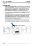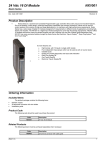
1
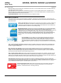
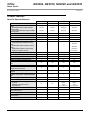
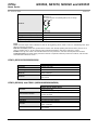
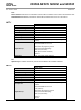
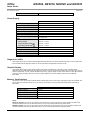
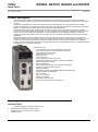
CPUs NX3004, NX3010, NX3020 and NX3030 Nexto Series Doc. Code: CE114100 Revision: H Product Description Nexto Series is a powerful and complete serie of Programmable Logic Controllers (PLCs) with exclusive and innovative features, targeted for covering control systems requirements from medium to large applications or high performance industrial machines. The diversity of available CPU models offer the ideal solution for every application, with high performance and a flexible architecture, allowing the use in applications ranging from large process automation to fast time-critical machinery automation. Besides, it combines high connectivity with the current high-speed industrial fieldbuses. Nexto Series CPUs were designed to fulfill several customers’ demands. Due to its compact and rugged body, excellent performance and fast I/Os update time provided by a unique high-speed communication bus, Nexto Series CPUs are the best choice for the most demanding control applications. In complex applications, where reliability, availability and remote I/O operation is required, Nexto Series CPUs are also a great choice due to its different redundant topologies and bus expansion possibilities. Nexto Series CPUs provide an innovative and unique enhanced diagnostics services. They take the user to a whole new diagnostics experience. By using a switch located on top of the module and a built-in compact graphical LCD display, the user has direct access to extensive information regarding I/Os, fieldbus interfaces and many other modules on the application. Finally, Nexto Series CPUs feature several communication interfaces such as serial and Ethernet ports, a miniSD card interface and full IEC 61131-3 programming languages. Its main features are: Up to 96 Kbytes of %I points and 96 Kbytes of %Q points Large memory capacity for user application and user data Up to 64 Kbytes of retain memory High-speed 32-bit processing Floating point unit Up to 2 serial ports Up to 2 Ethernet interfaces at front panel miniSD card interface (only in NX3010, NX3020 and NX3030) Enhanced diagnostics services System messages log Event oriented data reporting (only in NX3020 and NX3030) Support clock synchronization via SNTP Web server features Redundancy mode for high availability applications (NX3030 only) Integrated power supply (NX3004) One Touch Diag IEC 61131-3 compliant Real-time clock (RTC) Compact and modern design Free of moving parts (fans, active cooling, etc.) Ordering Information Included Items The product package contains the following items: NX3004, NX3010, NX3020 or NX3030 module 6-terminal connector with fixing (only in NX3004) Installation guide Altus S. A. 1 CPUs NX3004, NX3010, NX3020 and NX3030 Nexto Series Doc. Code: CE114100 Revision: H Product Code The following codes should be used to purchase the product: Code Description NX3004 CPU, 1 Ethernet port, 1 serial channel, remote rack expansion support and power supply integrated NX3010 High-speed CPU, 1 Ethernet port, 2 serial channels, memory card interface and remote rack expansion support NX3020 High-speed CPU, 2 Ethernet ports, 2 serial channels, memory card interface and remote rack expansion support NX3030 High-speed CPU, 2 Ethernet ports, 2 serial channels, memory card interface, remote rack expansion and redundancy support Related Products The following products must be purchased separately when necessary: Code Description MT8500 MasterTool IEC XE AL-2600 RS-485 network branch and terminator AL-2301 RS-485 network cable (up to 1000 meters) AL-2306 RS-485 network cable (up to 500 meters) AL-2319 RJ45-RJ45 Cable AL-1729 RJ45-CMDB9 Cable AL-1748 CMDB9-CFDB9 Cable AL-1752 CMDB9-CMDB9 Cable AL-1753 CMDB9-CMDB25 Cable AL-1754 CMDB9-CFDB9 Cable AL-1761 CMDB9- CMDB9 Cable AL-1762 CMDB9- CMDB9 Cable AL-1763 CMDB9-Terminal Block Cable NX9202 RJ45-RJ45 2 m Cable NX9205 RJ45-RJ45 5 m Cable NX9210 RJ45-RJ45 10 m Cable Notes: MT8500: MasterTool IEC XE is available in four different versions: LITE, BASIC, PROFESSIONAL and ADVANCED. For more details, please check MasterTool IEC XE User Manual - MU299609. AL-2600: This module is used for branch and termination of RS-422/485 networks. For each network node, an AL-2600 is required. The AL-2600 that is at the ends of network must be configured with termination, except when there is a device with active internal termination, the rest must be configured without termination. AL-2301: Two shielded twisted pairs cable without connectors, used for networks based on RS-485 interface, with 1000 meters of maximum length. AL-2306: Two shielded twisted pairs cable without connectors, used for networks based on RS-485 interface, with 500 meters of maximum length. AL-2319: Two RJ45 connectors for programming the CPUs of the Nexto Series and Ethernet point-to-point with another device with Ethernet interface communication. AL-1729: RS-232C standard cable with one RJ45 connector and one DB9 male connector for communication between CPUs of the Nexto Series and other Altus products of the DUO Series, Piccolo Series and Ponto Series. AL-1748: RS-232C standard cable with one DB9 male connector and 1 DB9 female connector for communication between CPUs of the Nexto Series and Altus products of the Cimrex Series. AL-1752: RS-232C standard cable with two DB9 male connectors for communication between CPUs of the Nexto Series and Altus products of the H Series and iX Series. AL-1753: RS-232C standard cable with one DB9 male connector and one DB25 male connector for communication between CPUs of the Nexto Series and Altus products of the H Series. AL-1754: RS-232C standard cable with one DB9 male connector and one DB9 female connector for o communication between CPUs of the Nexto Series and Altus products of the Exter Series or Serial port, RS-232C standard, of a microcomputer. Altus S. A. 2 CPUs NX3004, NX3010, NX3020 and NX3030 Nexto Series Doc. Code: CE114100 Revision: H AL-1761: Cable RS-232C standard with two DB9 male connectors for communication between CPUs of the Nexto Series and other Altus products of the AL series. AL-1762: Cable RS-232C standard with two DB9 male connectors for communication between CPUs of the Nexto Series. AL-1763: Cable with one DB9 male connector and terminal block for communication between CPUs of the Nexto Series and products with RS-485/RS-422 standard terminal block. NX9202/NX9205/NX9210: Cables used to interconnect the bus expansion modules. Innovative Features Nexto Series brings to the user several innovations in utilization, supervision and system maintenance. These features were developed focusing a new experience in industrial automation. The list below shows some new features that users will find in the Nexto Series CPUs: Battery Free Operation: Nexto Series does not require any kind of battery for memory maintenance and real time clock operation. This feature is extremely important because it reduces the system maintenance needs and allows the use in remote locations where maintenance can be difficult to be performed. Besides, this feature is environmentally friendly. Multiple Block Storage: Several kinds of memories are available to the user in Nexto Series CPUs, offering the best option for any user needs. These memories are divided in volatile memories and nonvolatile memories. For volatile memories, Nexto Series CPUs offer addressable input (%I), addressable output (%O), addressable memory (%M), data memory and redundant data memory. For applications that require non-volatile functionality, Nexto Series CPUs bring retain addressable memory (%Q), retain data memory, persistent addressable memory (%Q), persistent data memory, program memory, source code memory, CPU file system (doc, PDF, data) and memory card interface. One Touch Diag: One Touch Diag is an exclusive feature that Nexto Series brings to PLCs. With this new concept, the user can check diagnostic information of any module present in the system directly on CPU’s graphic display with one single press in the diagnostic switch of the respective module. OTD is a powerful diagnostic tool that can be used offline (without supervisor or programmer), reducing maintenance and commissioning times. OFD – On Board Full Documentation: Nexto Series CPUs are capable of storing the complete project documentation in its own memory. This feature can be very convenient for backup purposes and maintenance, since the complete information is stored in a single and reliable place. ETD – Electronic Tag on Display: Another exclusive feature that Nexto Series brings to PLCs is the Electronic Tag on Display. This new functionality brings the process of checking the tag names of any I/O pin or module used in the system directly to the CPU’s graphic display. Along with this information, the user can check the description, as well. This feature is extremely useful during maintenance and troubleshooting procedures. DHW – Double Hardware Width: Nexto Series modules were designed to save space in user cabinets or machines. For this reason, Nexto Series delivers two different module widths: Double Width (two backplane rack slots are required) and Single Width (only one backplane rack slot is required). This concept allows the use of compact I/O modules with a high-density of I/O points along with complex modules, like CPUs, fieldbus masters and power supply modules. High-speed CPU: All Nexto Series CPUs were designed to provide an outstanding performance to the user, allowing the coverage of a large range of applications requirements. For example: NX3010, NX3020 and NX3030 Nexto CPUs can execute a sum, multiplication and subtraction instruction in less than 15 ns for integer type values and in less than 23 ns for real type values. Nexto CPUs are able to perform 1,000 PIDs loops in less than 5 ms. iF Product Design Award 2012: Nexto Series was the winner of iF Product Design Award 2012 in industry + skilled trades group. This award is recognized internationally as a seal of quality and excellence, considered the Oscars of the design in Europe. Altus S. A. 3 CPUs NX3004, NX3010, NX3020 and NX3030 Nexto Series Doc. Code: CE114100 Revision: H Product Features Specific General Features NX3004 NX3010 NX3020 NX3030 Addressable input variables memory (%I) 32 Kbytes 32 Kbytes 64 Kbytes 96 Kbytes Total addressable output variables memory (%Q) Retain Addressable output variables memory (%Q) Persistent Addressable output variables memory (%Q) 32 Kbytes 32 Kbytes 64 Kbytes 96 Kbytes 2 Kbytes 8 Kbytes 16 Kbytes 16 Kbytes 2 Kbytes 8 Kbytes 16 Kbytes 48 Kbytes Addressable variables memory (%M) 16 Kbytes 16 Kbytes 32 Kbytes 64 Kbytes Symbolic variables memory 2 Mbytes 3 Mbytes 3 Mbytes 3 Mbytes Retain symbolic variables memory 2 Kbytes 32 Kbytes 48 Kbytes 32 Kbytes 1.5 Kbytes 16 Kbytes 32 Kbytes Persistent symbolic variables memory 16 Kbytes Total redundant data memory 736 Kbytes Addressable input variables memory (%I) 80 Kbytes Addressable output variables memory (%Q) - - - 80 Kbytes Addressable variables memory (%M) 64 Kbytes Symbolic variables memory 512 Kbytes Program memory 3 Mbytes 4 Mbytes 6 Mbytes 8 Mbytes Source code memory (backup) 32 Mbytes 40 Mbytes 80 Mbytes 120 Mbytes User files memory 16 Mbytes 16 Mbytes 32 Mbytes 32 Mbytes Maximum number of tasks 16 16 24 32 Maximum number of expansion bus 1 8 24 24 Maximum number of I/O modules on the bus 32 128 128 128 Ethernet TCP/IP local interface 1 1 2 2 Maximum number of additional Ethernet TCP/IP interface modules 0 0 2 6 No No Yes Yes Maximum number of PROFIBUS-DP network (using master modules PROFIBUSDP) 1 1 4 4 PROFIBUS-DP network redundancy support No No Yes Yes Redundancy support (half-clusters) No No No Yes Yes DNP3 1000 1 to 1000 bytes Ethernet TCP/IP interface redundancy support Event oriented data reporting (SOE) Protocol Maximum event queues size Data base size No No Yes DNP3 1000 1 to 1000 bytes Clock synchronization (SNTP) Yes Yes Yes Yes Web pages development (available trough the HTTP protocol) Yes Yes No No Power supply integrated Yes No No No - 800 mA 1000 mA 1000 mA 4W 4W 5W 5W Current consumption from backplane rack power supply Power dissipation Altus S. A. 4 CPUs NX3004, NX3010, NX3020 and NX3030 Nexto Series Doc. Code: CE114100 Revision: H Notes: Addressable input variables memory (%I): Area where the addressable input variables are stored. Addressable variables means that the variables can be accessed directly using the desired address. For instance: %IB0, %IW100. Addressable input variables can be used for mapping digital or analog input points. As reference, 8 digital inputs can be represented per byte and one analog input point can be represented per two bytes. Total addressable output variables memory (%Q): Area where the addressable output variables are stored. Addressable variables means that the variables can be accessed directly using the desired address. For instance: %QB0, %QW100. Addressable output variables can be used for mapping digital or analog output points. As reference, 8 digital outputs can be represented per byte and one analog output point can be represented per two bytes. The addressable output variables can be configured as retain, persistent or redundant variables, but the total size is not modified due to configuration. The Nexto Series NX3030 CPU allows defining an area of redundant variables inserted inside of the addressable output variables %Q. The subset of addressable output variables memories are part of the total size of available memory. Addressable variables memory (%M): Area where the addressable marker variables are stored. Addressable variables means that the variables can be accessed directly using the desired address. For instance: %MB0, %MW100. Symbolic variables memory: Area where the symbolic variables are stored. Symbolic variables are IEC variables created in POUs and GVLs during application development, not addressed directly in memory. Symbolic variables can be defined as retain or persistent. In these cases, it will be used the memory area of retain symbolic variables memory or persistent symbolic variables memory respectively. Retain symbolic variables memory: Area where the retain symbolic variables are stored. Retain data keeps its values even after a power on/power off cycle. Persistent symbolic variables memory: Area where the persistent symbolic variables are stored. Persistent data keeps its values even after the download of a new application into the CPU. Total redundant data memory: Redundant data memory is the maximum memory area that can be used as redundant memory between two redundant CPUs. This value is not a different memory, note that the sum of all redundant variables (addressable input variable, addressable output variable, addressable variable, symbolic variable, retain symbolic variable, persistent symbolic variable) must be less than or equal to the available redundant data memory. Program memory: Program memory is the maximum size that can be used to store the user application. This area is shared with source code memory, being the total area the sum of “program memory” and “source code memory”. Source code memory (backup): This memory area is used as project backup. If the user wants to import the project, MasterTool IEC XE will get the information required in this area. Care must be taken to ensure that the project saved as a backup is up to date to avoid the loss of critical information. This area is shared with source code memory, being the total area the sum of “program memory” and “source code memory”. User files memory: This memory area offers another way for the user to store files such as doc, pdf, images, and other files. This function allows data recording as in a memory card. More information can be found at Nexto Series CPUs User Manual – MU214605. Maximum number of tasks: The maximum number of tasks defined for each CPU model and each project profile can be found at Nexto Series CPUs User Manual – MU214605. Redundancy support (half-clusters): The firmware version 1.1.0.0 or onwards supports redundancy of NX3030 CPUs. Event oriented data reporting (SOE): The date types can be found at Nexto Series CPUs User Manual – MU214605. Maximum number of I/O modules on the bus: The maximum number of I/O modules on the bus refers the sum of all modules on the local bus and on the expansion bus. Maximum number of PROFIBUS-DP networks: From MasterTool IEC XE version 1.22 and onwards, 4 PROFIBUS-DP networks are supported for NX3020 and NX3030 CPUs. Previous versions support 2 PROFIBUS-DP networks. The limit of PROFIBUS-DP masters is 4, which means that 2 redundant networks can be used at most. Altus S. A. 5 CPUs NX3004, NX3010, NX3020 and NX3030 Nexto Series Doc. Code: CE114100 Revision: H Common General Features NX3004, NX3010, NX3020, NX3030 Backplane rack occupation 2 sequential slots Instruction List (IL) Structured Text (ST) Programming languages Ladder Diagram (LD) Sequential Function Chart (SFC) Function Block Diagram (FBD) Continuous Function Chart (CFC) Cyclic (periodic) Event (software interrupt) Tasks External (hardware interrupt) Freewheeling (continuous) Status (software interrupt) Online changes Yes Hot swap support Yes Bus coupler redundancy support Yes NX3004 – COM 1: 1 x RS-485 / RS-422 Serial interfaces NX3010/NX3020/NX3030 – COM 1: 1 x RS-232C NX3010/NX3020/NX3030 – COM 2: 1 x RS-485 / RS-422 RTU (COM 1 and COM 2) master and slave MODBUS protocol TCP (NET 1 and NET 2) client and server RTU via TCP (NET 1 and NET 2) client and server Real time clock (RTC) Yes Resolution of 1 ms and maximum variance of 2 s per day Watchdog Yes Status and diagnostic indication Graphic display, LEDs, web pages and CPU’s internal memory One Touch Diag (OTD) Yes Electronic Tag on Display (ETD) Yes Isolation Logic to protective earth 1250 Vac / 1 minute Logic to Ethernet interfaces 1500 Vac / 1 minute Logic to serial port (COM 2) 1000 Vac / 1 minute Logic to serial port NX3004 (COM 1) 1000 Vac / 1 minute Ethernet interfaces to protective earth Ethernet interfaces to serial port (COM 2) 1500 Vac / 1 minute Ethernet interfaces to serial port on the NX3004 (COM 1) 1500 Vac / 1 minute Ethernet interface to Ethernet interface 1500 Vac / 1 minute Serial port (COM 2) to protective earth Serial port N3004 (COM 1) to protective earth Altus S. A. 1250 Vac / 1 minute 1250 Vac / 1 minute 1000 Vac / 1 minute Operating temperature 0 to 60 °C Storage temperature -25 to 75 °C Relative humidity 5 to 96 %, non-condensing Conformal coating Yes IP Level IP 20 6 CPUs NX3004, NX3010, NX3020 and NX3030 Nexto Series Doc. Code: CE114100 Revision: H IEC 61131-2 IEC 61131-3 CE, Electromagnetic Compatibility (EMC) and Low-Voltage Directive (LVD) Standards Module dimensions (W x H x D) 36.00 x 114.63 x 115.30 mm Package dimensions (W x H x D) 44.00 x 122.00 x 147.00 mm Weight 350 g Weight with package 400 g Notes: Tasks: Task is an object used to call POUs. A Task can be triggered by period, events or can run in freewheeling mode. Each task can call one or more POUs. Real time clock (RTC): Retain time, period that the real time clock will keep updating date and time after a power off, is 15 days for operation at 25 °C. At the maximum product operation temperature, retain time is reduced to 10 days. Isolation: The Logic term refers to the internal interfaces such as processors, memories and backplane rack interfaces. Conformal coating: Conformal coating protects the electronic components inside the product from moisture, dust and other harsh elements to electronic circuits. COM 1 (NX3010/NX3020/NX3030) NX3010, NX3020, NX3030 Connector Shielded female DB9 Physical interface RS-232C Modem signals RTS, CTS, DCD Baud rate 200, 300, 600, 1200, 1800, 2400, 4800, 9600, 19200, 38400, 57600, 115200 bps Protocols Master/Slave MODBUS RTU Open protocol COM 1 (NX3004) and COM 2 (NX3010/NX3020/NX3030) NX3004, NX3010, NX3020, NX3030 Connector Shielded female DB9 Physical interface RS-422 or RS-485 (depending on the selected cable) Communication direction RS-485: half duplex RS-422 maximum transceivers 11 (1 transmitter and 10 receivers) RS-485 maximum transceivers 32 Termination Yes (optional via cable selection) Baud rate 200, 300, 600, 1200, 1800, 2400, 4800, 9600, 19200, 38400, 57600, 115200 bps Protocols Altus S. A. RS-422: full duplex Master/Slave MODBUS RTU Open protocol 7 CPUs NX3004, NX3010, NX3020 and NX3030 Nexto Series Doc. Code: CE114100 Revision: H Notes: Physical interface: Depending on the configuration of the used cable, it’s possible to choose the kind of physical interface: RS422 or RS-485. The list of cables can be found at Related Products section. RS-422 Maximum transceivers: Is the maximum number of RS-422 interfaces that can be used on the same bus. RS-485 Maximum transceivers: Is the maximum number of RS-485 interfaces that can be used on the same bus. NET 1 NX3004, NX3010, NX3020, NX3030 Connector Shielded female RJ45 Auto crossover Yes Maximum cable length 100 m Cable type UTP or ScTP, category 5 Baud rate 10/100 Mbps Physical layer 10/100 BASE-TX Data link layer LLC (logical link control) Network layer IP (internet protocol) Transport layer TCP (Transmission Control Protocol) and UDP (User Datagram Protocol) Client/Server MODBUS TCP Client/Server MODBUS RTU via TCP HTTP (web server) MasterTool IEC XE programming protocol Application layer DNP3 (event oriented data reporting) SNTP (clock synchronism) SNMP (Ethernet network management) EtherCAT OPC DA Diagnostics LEDs - green (speed), yellow (link/activity) Note: Application layer: The DNP3 and EtherCAT protocols are not available for UCPs NX3004 and NX3010. NET 2 NX3020, NX3030 Connector Shielded female RJ45 Auto crossover Yes Maximum cable length 100 m Cable type UTP or ScTP, category 5 Baud rate 10/100 Mbps Physical layer 10/100 BASE-TX Data link layer LLC (logical link control) Network layer IP (Internet Protocol) Transport layer TCP (Transmission Control Protocol) and UDP (User Datagram Protocol) Client/Server MODBUS TCP Client/Server MODBUS RTU via TCP HTTP (web server) MasterTool IEC XE programming protocol Application layer DNP3 (event oriented data reporting) SNTP (clock synchronism) SNMP (Ethernet network management) EtherCAT OPC DA Altus S. A. 8 CPUs NX3004, NX3010, NX3020 and NX3030 Nexto Series Doc. Code: CE114100 Diagnostic Revision: H LEDs - green (speed), yellow (link/activity) Power Supply NX3004 Nominal input voltage 24 Vdc Maximum output power 15 W Maximum output current 3A Input voltage 19.2 to 30 Vdc Maximum input current (in-rush) 30 A Maximum input current 1.4 A Typical efficiency 92 % @ 24 Vdc Maximum input voltage interrupt time 10 ms @ 24 Vdc Isolation Input to output 1000 Vac / 1 minute Input to protective earth 1500 Vac / 1 minute Input do functional earth 1000 Vac / 1 minute Wire size 0.5 mm² Polarity inversion protection Yes Internal auto recovery fuse Yes Output short-circuit protection Yes Overcurrent protection Yes Diagnostics LEDs Nexto Series CPUs have one LED to indicate diagnostics (DG LED) and one LED to indicate watchdog occurrence (WD LED). More information about diagnostics LEDs can be found at Status and Diagnostic Indicators section. Graphic Display Nexto Series CPUs have a graphic display used to show status and diagnostics of the entire system, including specific diagnostics of each additional module. The display also offers an easy-to-use menu that brings to the user a fast way to read or set some parameters, such as: internal temperature (read only); graphic display contrast and IP address for each NET interface (read only). More information about how to use the graphic display can be found at Nexto Series CPUs User Manual MU214605. Memory Card Interface The memory cards can be used for different kinds of data storage, such as user’s logs, web pages, project documentation and source files. More information about how to use memory card Interface can be found at Nexto Series CPUs User Manual MU214605. NX3010, NX3020, NX3030 Maximum capacity 8 Gbytes Minimum capacity 2 Gbytes Type miniSD File system FAT32 Safe card removal Yes, by pressing MS switch Notes: Maximum capacity: The memory card capacity must be less than or equal to this limit for correct operation on Nexto CPU, otherwise the Nexto CPU may not detect the memory card or even present problems during data transfer. Minimum capacity: The memory card capacity must be greater than or equal to this limit for correct operation on Nexto CPU, otherwise the Nexto CPU may not detect the memory card or even present problems during data transfer. Altus S. A. 9 CPUs NX3004, NX3010, NX3020 and NX3030 Nexto Series Doc. Code: CE114100 Revision: H File system: It is recommended to format the memory card using the Nexto CPU, otherwise it may result in performance loss in the memory card interface. The copy of application to/from memory card is available only in firmware version 1.1.0.26 onwards and MasterTool IEC XE version 1.22 onwards. CPU Redundancy Nexto Series offers CPU redundancy. The redundant CPUs can be located in different racks (known as half-clusters). In the redundant architecture, the system will have one CPU running (active CPU) and another one acting as the standby CPU, standby CPU is capable of automatic switchover in case of a primary controller failure. This means that critical processes are not affected by control system hardware failures. The result is increased productivity and minimized downtime. The communication between the CPUs is done at the end of each scan cycle through two high-speed redundancy links. The examples below demonstrate two redundant modes provided by Nexto Series. More information about how to configure and use CPU’s redundant features can be found at Nexto Series CPUs User Manual - MU214605. Half-Cluster Redundancy This redundancy option uses two racks with one CPU and one redundancy interface module in each rack. In this case, each rack is called “half-cluster”. Each half-cluster also can have one or more fieldbus master modules that are responsible for communicating with all remote I/Os. When an error at the active half-cluster occurs, the standby half-cluster takes over and its fieldbus master module becomes the bus master of the fieldbus network. This application is easy to set-up, with no special programming or parameterization needed by the user. In this redundant mode, the CPU and the redundancy link module must be placed side by side. The figure below brings an example of rack with a half-cluster redundant topology: 5 Diagram Notes: 1- At the core of a two half-cluster redundant system, there is a pair of redundant CPUs. 2- The links between two half-clusters have two channels. So, failures at individual channels will not affect system performance. 3- Configuration of both systems shall be identical (half-clusters). 4- This example has network modules with protocols based on Ethernet. There are two network modules for each purpose: a control network and a supervision network for SCADA. 5- The redundancy panel PX2612 is optional to half-cluster redundancy. It must be used when the redundancy with panel PX2612 option is selected during the MasterTool IEC XE wizard setup. Altus S. A. 10 CPUs NX3004, NX3010, NX3020 and NX3030 Nexto Series Doc. Code: CE114100 Revision: H Compatibility with Other Products There are some incompatibilities between Nexto Series CPUs and MasterTool IEC XE. Consult the following table to know which MasterTool IEC XE version should be used. CPU’s software version NX3010, NX3020 and NX3030 Compatible version of MasterTool IEC XE 1.2.0.9 or lower 1.00 to 1.28 1.2.1.0 to 1.2.4.0 1.29 to 1.40 1.3.0.20 1.40 to 1.41 1.4.0.33 2.00 or higher Note: Compatibility between versions: There are some limitations to functionality, some are only available from a certain version. See the section of the User Manual MasterTool IEC XE - MU299609 on the functionality to check the availability of certain characteristic in a specific version of programmer. Physical Dimensions NX3004 Dimensions in mm. Altus S. A. 11 CPUs NX3004, NX3010, NX3020 and NX3030 Nexto Series Doc. Code: CE114100 Revision: H NX3010, NX3020 and NX3030 Dimensions in mm. Installation All information about electrical installation, mechanical assembly and module insertion can be found at Nexto Series User Manual - MU214600. Configuration Nexto Series CPUs were developed to be used with Nexto Series products. All Nexto Series products are configured through MasterTool IEC XE. Information about the right procedures to add/remove modules to/from the system can be found at Nexto Series User Manual – MU214600. Information about CPU configuration can be found on the Nexto Series CPUs User Manual MU214605. Programming Nexto Series CPUs use the IEC 61131-3 standard languages, which are IL, ST, LD, SFC and FBD. IL and ST are textual languages and they are similar to Assembly and C languages respectively, while LD, SFC and FBD languages are graphical. LD uses the representation of relays and blocks and it is similar to relay diagrams. SFC uses the representation of a sequence diagram, allowing an easy way to view a sequence of events. FBD uses an arrangement of function blocks, allowing a clear view of functions performed on each action. Nexto Series CPUs also offer a sixth language, CFC. The programming is performed on the MasterTool IEC XE interface. The IDE enables the use of six languages in the same project, thus providing the best features that each language can offer to the user, resulting in efficient application developments, allowing easy documentation and future maintenance. For more information about programming, see the MasterTool IEC XE User Manual - MU299609, MasterTool IEC XE Programming Manual - MP399609, the IEC 61131-3 standard or the Nexto Series CPUs User Manual - MU214605. Altus S. A. 12 CPUs NX3004, NX3010, NX3020 and NX3030 Nexto Series Doc. Code: CE114100 Revision: H Maintenance Altus recommends that all modules’ connections be checked and that all dust or any kind of dirt located at the module’s enclosure be removed at least every 6 months. Nexto Series CPUs offer five important features to assist the user during maintenance: Electronic Tag on Display, One Touch Diag and status and diagnostics indicators, web page with complete status and diagnostics list and status and diagnostics mapped to internal memory. Electronic Tag on Display and One Touch Diag Electronic Tag on Display and One Touch Diag are important features that provides for the user the option to check the tag, description and diagnostics related to a given module directly on the CPU display. Electronic Tag on Display and One Touch Diag are easy-to-use features. To check the tag and diagnostics of a given module, it’s required only one short press (shorter than 1 s) on its diagnostic switch. After pressing once, CPU will start to scroll tag information and diagnostic information of the module. To access the respective description for the module just long press (longer than 1 s) the diagnostic switch of the respective module. More information about Electronic Tag on Display can be found at Nexto Series User Manual – MU214600 and at Nexto Series CPUs User Manual – MU214605. Status and Diagnostic Indicators All Nexto Series CPUs have a graphic display that brings useful status and diagnostics to the user, such as application states (run and stop), miniSD card status, serial interfaces activity (RX and TX) and others. In addition, Nexto Series CPUs also provide two LEDs that are used to indicate status and diagnostics. The tables below show the meaning of each state of DG LED and WD LED: DG (Diagnostic) Green color Red color Description Off Off Not used Causes No power supply. Hardware problem. Priority - On Off All applications running (Run Mode) - 3 (Lower) Off On All Application stopped (Stop Mode) - 3 (Lower) Blinking 2x Off Bus modules with diagnostic At least one module, including CPU, has some active diagnostic. 1 Blinking 3x Off Forced data Some memory area is forced by the user via MasterTool IEC XE. 2 Off Blinking 4x Bus configuration/hardware error The bus is not correctly configured or the bus is damaged. 0 (Higher) WD (Watchdog) Red color Description Causes Priority Off No watchdog indication Normal operation. 3 (Lower) Blinking 1x Application watchdog User application watchdog. 2 On Hardware watchdog Module malfunction. 1 (Higher) Notes: Software Watchdog: To clear the watchdog indication, the module must be disconnected from the power supply or the application must be reset. This watchdog happens when the duration of the user application execution is larger than the configured watchdog time. Hardware Watchdog: To clear any watchdog indication, such as WD LED or in the variable Reset.bWatchdogReset, the module must be disconnected from the power supply. Altus S. A. 13 CPUs NX3004, NX3010, NX3020 and NX3030 Nexto Series Doc. Code: CE114100 Revision: H Web Page with Complete Status and Diagnostic List Another way to access diagnostic information on Nexto Series is via web pages. Nexto Series CPUs have an embedded web page server that provides all status and diagnostic information that can be accessible using a simple browser on a computer, tablet or smartphone. Diagnostics via Variables The list of all module specific status and diagnostics can be found on the Nexto Series CPUs User Manual - MU214605. Manuals For correct application and utilization, Nexto Series CPUs User Manual - MU214605 must be consulted. For further technical details, configuration, installation and programming of Nexto Series the table below should be consulted. This table is only a guide of some relevant documents that can be useful during the use, maintenance, and programming of NX3004, NX3010, NX3020 and NX3030. The complete and updated table containing all documents of Nexto Series can be found at Nexto Series User Manual – MU214600. Altus S. A. Document code Description Language CE114000 CT114000 CS114000 Nexto Series – Technical Characteristics Série Nexto – Caracteristicas Técnicas Serie Nexto – Especificaciones y Configuraciones English Portuguese Spanish MU214600 MU214000 MU214300 Nexto Series User Manual Manual de Utilização Série Nexto Manual Del Usuario Serie Nexto English Portuguese Spanish MU214605 MU214100 MU214305 Nexto Series CPUs User Manual Manual de Utilização UCPs Série Nexto Manual del Usuario UCPs Serie Nexto English Portuguese Spanish MU299609 MU299048 MU299800 MasterTool IEC XE User Manual Manual de Utilização MasterTool IEC XE Manual del Usuario MasterTool IEC XE English Portuguese Spanish MP399609 MP399048 MP399800 MasterTool IEC XE Programming Manual Manual de Programação MasterTool IEC XE Manual de Programación MasterTool IEC XE English Portuguese Spanish 14