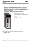
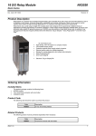
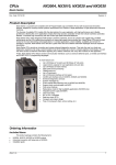
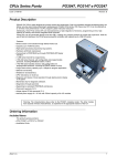
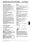
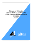
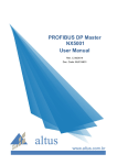
1
PROFIBUS-DP Heads NX5110, NX5210 Nexto Series Doc Code : CE114908 Product Description The Nexto Series is a powerful and complete series of Programmable Controllers (CP) with unique and innovative features. Due to its flexibility, intelligent design, advanced diagnostic capabilities and modular architecture, Nexto series can be used to control systems in medium and large applications. Due to its compact size, high density of points for modules and superior processing capability, the Nexto can also be applied in smaller automation systems with high performance requirements, such as manufacturing and industrial applications. The Nexto Series presents a wide variety of modules for communication with networks with features to suit different types of application. The NX5110 and NX5210 modules are devices of type head-slave for PROFIBUS-DP networks, allowing the user to use all modules I/O Series Nexto. Its main features are: PROFIBUS-DP Protocol for communication of I/O data High communication speed (baud rate up to 12 Mbits/s) Compatible with any PROFIBUS-DP master equipment, following the standard EN 50170 PROFIBUS-DP network addressing in the front Ability to use up to 22 I/O modules in a single rack Redundancy support (using two heads NX5210) Support hot swap (only NX5210) Support hot swap I/O modules Auto-parameterization and configuration of the I/O modules via PROFIBUS-DP master (class 1) Automatic baud rate detection Expansion I/O modules without the need to disable the network (hot expansion) Ethernet interface for firmware update Local advanced diagnostic service Diagnoses and States of local operation via LEDs, and display in the Panel One Touch Diag Free of moving parts (fans, coolers, etc.) Ordering Information Included Items The product package contains the following items: NX5110 or NX5210 module 6 Terminals Connector Installation Guide Product Code The following codes should be used to purchase the product: Code Altus S. A. Description NX5110 PROFIBUS-DP Head NX5210 PROFIBUS-DP Redundant Head 1 PROFIBUS-DP Heads NX5110, NX5210 Nexto Series Doc Code : CE114908 Related Products The following codes should be used to purchase the product: Code Description NX9000 8-Slot Backplane Rack NX9001 12-Slot Backplane Rack NX9002 16-Slot Backplane Rack NX9003 24-Slot Backplane Rack NX9404 6 Terminal Connector Fixation NX3004 CPU with 1 Ethernet port, 1 serial channel, support for expansion bus and integrated power supply NX3010 High speed CPU, 1 Ethernet port, 2 serial channels, memory card interface and support for bus expansion NX3020 High speed CPU, 2 Ethernet ports, 2 serial channels, memory card interface and support for bus expansion NX3030 High speed CPU, 2 Ethernet ports, 2 serial channels, memory card interface, support the expansion bus and support for redundancy AL-2601 PROFIBUS-DP Derivador Connector AL-2602 PROFIBUS-DP Termination Connector AL-2605 Terminator With Supply Diagnostic AL-2303 PROFIBUS Network Cable A Type AL-2431 Optical Repeater FOCOS/PROFIBUS AL-2432 Optical Repeater FOCOS/PROFIBUS with Two Optical Ports AL-2433 PROFISwitch – Coupler for Redundant Profibus Network NX5001 PROFIBUS-DP Master Interface PO4053 PROFIBUS-DP Master Interface AL3406 PROFIBUS-DP Master Interface MT8500 MasterTool IEC XE Notes: AL-2601: the derivador connector for PROFIBUS-DP network is a connector type DB9 with standardized pinout according to EN 50170 and without termination. It is suitable for connection to PROFIBUS-DP devices mounted on intermediate positions in the PROFIBUS-DP network, i.e. physically not mounted at the ends of the network. This connector has input and output connection of the cable network, enabling disconnection be done without disrupting the continuity of the physical network AL-2602: PROFIBUS-DP terminator connector is a connector type DB9 with standardized pinout according to EN 50170 and termination. It is suitable for connection to PROFIBUS-DP devices mounted on the ends of the physical network (beginning and end) AL-2605: the terminator with diagnosis of font is used in the extremes of redundant networks, where is needed to make the exchange of devices without losing the endings AL-2303: cable for data communication on PROFIBUS-DP network AL-2431 e AL-2432: optical repeaters for interconnection between any PROFIBUS-DP equipment through optical fiber. The module AL-2432 has redundancy of optical transmission by adding increased availability to the system NX5001: PROFIBUS-DP Master – Nexto Series PO4053: PROFIBUS-DP Master – Ponto Series AL3406: PROFIBUS-DP Master – AL Series MT8500: MasterTool IEC XE is available in four different versions: LITE, BASIC, PROFESSIONAL and ADVANCED. For more information, please consult the user Manual of the MasterTool IEC XE-MU299609 Altus S. A. 2 PROFIBUS-DP Heads NX5110, NX5210 Nexto Series Doc Code : CE114908 Innovative Features The Nexto Series brings users various innovations in use, supervision and maintenance of the system. These features were developed focusing on a new concept in industrial automation. The list below shows some of the features that the user will find NX5110 and NX5210 modules: One Touch Diag: One Touch Diag is an exclusive feature that Nexto Series brings to PLCs. With this new concept, user can check diagnostic information of any module present in the system directly on CPU’s graphic display with one single press in the diagnostic switch of the respective module. OTD is a powerful diagnostic tool that can be used offline (without supervisor or programmer), reducing maintenance and commissioning times. DHW – Double Hardware Width: Nexto Series modules were designed to save space in user cabinets or machines. For this reason, Nexto Series delivers two different module widths: Double Width (two backplane rack slots are required) and Single Width (only one backplane rack slot is required). This concept allows the use of compact I/O modules with a highdensity of I/O points along with complex modules, such as CPUs, fieldbus masters and power supply modules. IF Product Design Award 2012: Nexto Series was the winner of iF Product Design Award 2012 in industry + skilled trades group. This award is recognized internationally as a seal of quality and excellence, considered the Oscars of the design in Europe. Product Features Specific General Features Module Type Communication Protocol NX5110 NX5210 PROFIBUS-DP Fieldbus Head PROFIBUS-DP Fieldbus Redundant Head PROFIBUS-DP, standard EN 50170 Sync/Freeze Support Yes Backplane Rack Occupation Maximum Number of Modules 2 Sequential Positions 22 20 Input Capacity 240 input bytes 238 data bytes + 2 bytes regarding the head status Output Capacity 240 data bytes 238 data bytes + 2 bytes of User Commands Baud rate Automatic Baud rate detection from 9,6 to 12.000 Kbit/s Ethernet Port Baud Rate 10/100 Mbps Status and Diagnostics Indication Display, web page and LEDs Network Redundancy Support No Hot Swap Support No Yes Yes I/O Hot Swap Support Yes One Touch Diag (OTD) Yes Electronic Tag on Display (ETD) Yes Attended Standards Altus S. A. - PROFIBUS GUIDE-LINE ORDER no. 2.212PROFIBUS SPECIFICATION SLAVE REDUNDANCY version 1.0 3 PROFIBUS-DP Heads NX5110, NX5210 Nexto Series Doc Code : CE114908 - PROFIBUS European Norm EN 50170 - IEC 61131-2:2003, chapters 8 and 11 - CE directives for electromagnetic compatibility (EMC) and low voltage (Low-Voltage Directive-LVD). See general features of the series. GSD File Isolation PROFIBUS Interface to Logic PROFIBUS Interface to Earth Protection Logic to Earth Protection Input Voltage ALT_0EDD.GSD ALT_0EDE.GSD 1000 Vac / 1 minute 1000 Vac / 1 minute 1250 Vac / 1 minute 19,2 a 30 Vdc Max Input Current (in-rush) 30 A Max Input Current 1.4 A Max Current Provided to the Bus 3A Dissipation 5W IP Level IP 20 Operating Temperature Storage Temperature Operation and Storage Relative Humidity Conformal Coating Standards 0 a 60 °C -25 a 75 °C 5 a 96 %, non-condensing Yes IEC 61131-2 Module dimensions (W x H x D) 36,00 x 114,63 x 115,30 mm Package dimensions (W x H x D) 44,00 x 122,00 x 147,00 mm Weight 200 g Weight with Package 250 g Notes: Maximum Number of Modules: The maximum number of modules is related to greater backplane rack available in Series Nexto, with 24 positions, two positions are occupied by the NX5110 module, allowing the use of a maximum of 22 modules in this frame. There are still other limits that are to be taken into consideration, such as the consumption of each I/O module and also the number of bytes of input and output that each module has. In this way, this limit may be reduced in the light of these other requirements Input Capacity: Each PROFIBUS-DP remote's ability to convey the master module the limit of 240 bytes of input, thus it is necessary to consult the user Manual of the Nexto PROFIBUS-DP Head-MU214608 the number of bytes of each module entry consumes. For example, the HSC NX1001 module (module NX1001 counter mode enabled) has 16 bytes of input. Output Capacity: Each PROFIBUS-DP remote has the ability to receive the master module the limit of 240 bytes of output, thus it is necessary to consult the user Manual of the Nexto PROFIBUS-DP Head -MU214608 the number of bytes of each module output consumes. For example, the HSC NX1001 module (module NX1001 counter modes enabled) has 11 bytes of output. Baud rate: The baud rate is detected in the following communication speeds: 9.6 kbits/s, 19.2 Kbit/s, 93.75 Kbit/s, 187.5 Kbit/s, 500 Kbit/s, 1500, 3000 Kbit/s Kbit/s Kbit/s 6000 and 12000 Kbit/s. Network redundancy support: his implementation is described in the System Settings section. Isolation: In order to identify the different circuits and component sets that have isolation on the product, the term logic is the name given the internal interfaces as memories, and interfaces with the rack. Max Current Provided to the Bus: The modules NX5110 and NX5210 have an integrated power supply that can provide to the bus 3 A of current to power the I/O modules. Conformal Coating: The coating of electronic circuitry protects the internal parts of the product against humidity, dust and other harsh elements to electronic circuits. Altus S. A. 4 PROFIBUS-DP Heads NX5110, NX5210 Nexto Series Doc Code : CE114908 ATTENTION: The modules NX5110 and NX5210 do not have network terminators, requiring the use of external termination modules. Power Supply NX5110, NX5210 Nominal Input Voltage 24 Vdc Maximum Output Power 15 W Maximum Output Current 3A Input Voltage 19,2 a 30 Vdc Maximum Input Current 30 A Typical Efficiency 92 % @ 24 Vdc Maximum input voltage interruption 10 ms Isolation Input to Output 1000 Vac / 1 minute Input to Earth Protection 1500 Vac / 1 minute Input to Functional Earth 1500 Vac / 1 minute Wire Gauge 0,5 mm² Reverse polarity protection Yes Internal Resettable fuse Yes Short-circuit protection on the output Yes Over Current Protection Yes Diagnostics LEDs PROFIBUS-DP heads NX5110 and NX5210 of Nexto Series have two LEDs, and an LED to indicate diagnoses (LED DG), another LED to indicate the occurrence of watchdog (WD LED). More information about diagnostic LEDs can be found in Status and diagnostic Indicators section. Graphical Display PROFIBUS-DP heads NX5110 and NX5210 of Nexto Series have a graphical display used to show the status and diagnosis of the entire system, including the additional module-specific Diagnostics. More information about how to use the graphical display can be found in the user Manual of the PROFIBUS-DP Head Nexto-MU214608. I/O Capacity NX5110 A remote PROFIBUS-DP, with the NX5110 module, has its limited capacity by the following values: total number of modules in the same backplane rack: 22 maximum number of bytes to be transmitted over the network: 240 input bytes and 240 output bytes NX5210 A remote PROFIBUS-DP, with the NX5210 module, has its limited capacity by the following values: total number of modules in the same backplane rack: 20 maximum number of bytes to be transmitted over the network: 238 input bytes + 2 redundancy control bytes and 238 output bytes + 2 redundancy control bytes I/O Modules The maximum number of points depends on the type of points used. For example, the threshold for digital is 640 points (20 modules). But for analog the limit points are 96 points (12 modules). The maximum number of a mixed configuration is limited by the maximum number of total bytes, depending on the model of the PROFIBUS-DP head used. The density, in bytes, of the I/O modules can be seen below: Altus S. A. 5 PROFIBUS-DP Heads NX5110, NX5210 Nexto Series Doc Code : CE114908 16 points digital modules: 2 bytes Digital module NX1001 in HSC mode: 16 input bytes and 11 output bytes Digital Module NX1005 in HSC mode: 15 input bytes and 12 output bytes 8 points Analog Modules: 16 bytes For further details see the User Manual of Nexto PROFIBUS-DP Head (MU214608) Integrated Power Supply Capacity NX5110 and NX5220 heads have integrated power supply with a maximum current capacity of 3 amps. This feature allows feed I/O modules without the need for additional modules on bus. However, you should consult the consumption of each I/O module in their respective technical specifications (CEs) to the proper system configuration. In the redundant head NX5210, the fact of existing source redundancy does not increase the ability of bus modules. Altus S. A. 6 PROFIBUS-DP Heads NX5110, NX5210 Nexto Series Doc Code : CE114908 System Settings “A” Setup: Single PROFIBUS-DP Network: The PROFIBUS-DP network configuration allows simple connection between a master and slave devices through a single network. The following figure illustrates this connection by using Nexto Series PROFIBUS-DP Master NX5001, however, this same link can be applied with other PROFIBUS-DP master. Altus S. A. 7 PROFIBUS-DP Heads NX5110, NX5210 Nexto Series Doc Code : CE114908 "B” Setup: Redundant PROFIBUS-DP Network: The redundant PROFIBUS-DP network configuration allows to maintain the redundant system operating even occurring a failure in a redundant slave's head, interruption in data transmission or line failure in one of the Master Interfaces. This type of configuration consists of a CPU connected to two PROFIBUS-DP Master Interfaces (NX5001). These interfaces make up networks A and B, each with their heads NX5210. In the example below the bus consists of a CPU NX3030 and two Nexto PROFIBUS-DP NX5001 Masters. Altus S. A. 8 PROFIBUS-DP Heads NX5110, NX5210 Nexto Series Doc Code : CE114908 "C” Setup: Redundant PROFIBUS-DP Network: Allows to maintain the operation of the system even in a failure in of a redundant slave's head, a disruption of data transmission lines, in one of the Interfaces or in one of the masters. This type of configuration consists of two Master's PLCs, each connected to two Master PROFIBUS-DP Interfaces. In the example presented each CPU is composed of a NX3030 and two Nexto PROFIBUS-DP NX5001 Masters. Altus S. A. 9 PROFIBUS-DP Heads NX5110, NX5210 Nexto Series Doc Code : CE114908 Software Features The Nexto Series brings to the user the MasterTool IEC XE, a powerful tool that provides a complete interface for programming of all modules of Nexto Series. This means that there is no need for other software to perform the configuration of the PROFIBUS-DP Slave. All configurations are done in the same software used for programming the Nexto Series CPUs. Another important point is that all the parameterization of PROFIBUS-DP Slave is sent to the NX5001 module through the Nexto Series CPU, not needing special cables to the module's configuration. Compatibility with Other Products NX5110 The following table provides information concerning the compatibility between the NX5110 module with the programming tool IEC MasterTool XE and other Nexto Series Modules. Software Version Software Version NX5001 1.2.0.0 or above AG MT8500 2.01 AQ NX5210 The following table provides information concerning the compatibility between the NX5210 module with the programming tool IEC MasterTool XE and other Nexto Series Modules. Software Version Software Version NX5001 1.2.0.0 or above AG MT8500 2.01 AQ Redundancy Capacity NX5210 head has the ability to be linked to other NX5210, share the same I/O modules, forming a redundant System which provides greater reliability to the fieldbus network. The redundant system implemented is the Altus redundancy System, based on the European standard of PROFIBUS-DP Redundancy. Altus Redundancy System Implementation The redundancy system consists basically of two fieldbus network heads NX5210 connected via backplane rack of Nexto Series I/O modules. These heads are each connected in a Master PROFIBUS-DP interface. One of these heads, called Active is responsible for reading and writing in input and output modules. The other head, called Standby, has the function of monitoring. When the Active Head, presents some problem, the Standby head takes over the control of Nexto Series backplane rack, without any damage to the application being executed. The redundancy system has the following features (according to PROFIBUS-DP Redundancy Standard): Altus S. A. NX5210 modules can be connected individually on PROFIBUS-DP networks. In this case, the modules must have the same network address The redundancy system can be implemented by masters who do not possess the characteristics of redundancy. For this it is necessary that the application on CPU to implement redundancy algorithm described in the Nexto Head PROFIBUS-DP User Manual The redundancy system can be implemented with a master that suits the way of implementation of the NX5210 module (NX5001 PROFIBUS-DP Master for example) Redundancy informations are controlled by a virtual module and accessed by master in the same way as an ordinary I/O module The Standby Head is identified in the display An expansion can be made of nodes/modules without disabling the PROFIBUS-DP network (Hot-expansibility) through the redundancy system Owns a security state that sustains the parameterizable time outputs if the redundancy system has no communication with the Master Allows hot swap of any of the NX5210 heads without affecting the application. This operation is possible provided that the two heads are in Active or Standby status, respectively Through master's commands it is possible to request the return of Active/standby state (switchover) to redundant system 10 PROFIBUS-DP Heads NX5110, NX5210 Nexto Series Doc Code : CE114908 Physical Dimensions Dimensions in mm. Altus S. A. 11 PROFIBUS-DP Heads NX5110, NX5210 Nexto Series Doc Code : CE114908 Installation Electrical Assembly The installation in rack (rack backplane) can be seen in the figure below. Diagram Notes: 1, 2- The address of the PROFIBUS-DP Slave is set by key x 1 and x 10 so that the unit is set in the key x 1 and the dozen is set in the key x 10. As an example, the rack with address 15 must have 5 in x 1 and 1 in x 10 3- Standard Ethernet interface 10/100Base-TX to access the Diagnostics and Firmware update through Web page 4- Use the cable AL-2303 for PROFIBUS-DP fieldbus network and one of the following connectors: AL-2601 is a connector for PROFIBUS-DP fieldbus network without internal termination. It can be used to connect any PROFIBUS-DP equipment in a position in which the termination is not required. AL-2602 is a connector for PROFIBUS-DP fieldbus network with internal termination. It should be used on PROFIBUS-DP equipment located at the ends of the fieldbus network. Altus also offers a second option for requirements where reliability and availability are key requirements. For these cases a connector AL-2605 should be used at each end of the field network and all modules PROFIBUS-DP without internal termination connectors should be used with AL-2601. More information about the AL-2605 module can be found in document CE104705 The use of two network PROFIBUS-DP terminations is obligatory. Each termination should be positioned at each end of the network fieldbus. 5- The grounding from the external power source is connected to the terminal . Use 0,5 mm² cables 6- The power supply is connected to terminal 0 v. Use 0.5 mm ² cables 7- The power supply is connected to terminal 24 v. Use 0.5 mm ² cables 8- The power supply feeds the internal circuit directly 9- Local data bus 10- The module feeds the other modules of the Nexto Series through rack connection 11- The grounding of the module is done via the Nexto Series rack Altus S. A. 12 PROFIBUS-DP Heads NX5110, NX5210 Nexto Series Doc Code : CE114908 Mechanical Assembly The mechanical Assembly for this module is described in the user Manual Series Nexto-MU214600. There is no special point about the installation of this module. Parametrization The parameterization of the head and the connected modules is made by the PROFIBUS-DP master. The parameters of the head are transmitted via the PROFIBUS-DP network, without the need for additional configuration. The parameters of the head are described in its Manual. The parameterization of the modules is described in the CEs. GSD File All head's configurable options and the modules are defined in a file named PROFIBUS-DP GSD standard. This file follows the programmer MasterTool IEC XE. To use the head with other master manufacturers the file can be obtained at www.altus.com.br or with the support of Altus. Maintenance Altus recommends that all modules’ connections be checked and that all dust or any kind of dirt located at the module’s enclosure be removed at least every 6 months. The NX5110 and NX5210 modules offer four important features to assist the user during maintenance: One Touch Diag, Diagnostics and Status Indicators and Diagnostics mapped in internal memory. One Touch Diag One Touch Diag is an important feature that allows the user the option to verify the diagnoses related to a given module directly in the graphical display of the head. One Touch Diag is an easy-to-use functionality. To verify the diagnosis of a given module just a short press (less than 1 second) on the diagnostic button. After pressing the Head will show the module Diagnostics. More information on One Touch Diag can be found in the user Manual Series Nexto-MU214600. Status and diagnostic Indicators The modules NX5110 and NX5210 have graphical display containing status and information of interest to the user, such as: operating mode of the interface with network redundancy enabled, IP address of the Ethernet interface, Sync mode indication and/or Freeze. Additionally, it also provides Diagnostics related to interface and PROFIBUS-DP network LED DG. A second LED is used to indicate the occurrence of watchdog (WD LED). DG (Diagnostic) Green Red Description Causes Priority On Off Cyclical data are exchanged with master Communication with PROFIBUS-DP master was established 5 (Lowe) Blinking 2x Off Bus modules with diagnosis Some bus module, including the head has Active diagnosis 4 Blinking 4x Off Without configuration PROFIBUS-DP master has not yet sent the parameterization and configuration 3 Off Blinking 1x Configuration or Hardware error on bus Configuration / Parametrization Error Check diagnosis structure 2 Off On No activity in PROFIBUS-DP network - PROFIBUS-DP network cable faulty - Network cable not connected - PROFIBUS-DP termination error 1 Off Off Head’s hardware error - Fatal hardware Problem - Error in memory of PROFIBUS-DP coprocessor 0 (Higher) Altus S. A. 13 PROFIBUS-DP Heads NX5110, NX5210 Nexto Series Doc Code : CE114908 WD (WatchDog) Green Red Description Causes Priority Off Off No Watchdog indication Normal Operation 3 (Lower) Off Blinking 1x Software Watchdog Watchdog generated by software 2 Off On Hardware Watchdog Damaged Module 1 (Higher) Notes: Software Watchdog: To remove the indication of watchdog, it’s necessary to unplug and reconnect the module. This watchdog occurs when the runtime of the internal software is longer than one second. If this error manifests itself with frequency, contact should be carried out with the technical support of Altus. Hardware Watchdog: To clear any indication of watchdog, as the WD LED or tDetailed.Reset.bWatchdogReset operand, it is necessary to disconnect and reconnect the module. Graphical Display The NX5110 and NX5210 Nexto Series modules have a graphical display used to show the status and diagnostic system, including the additional module-specific Diagnostics. More information about how to use the graphical display can be found in the User Manual of Nexto PROFIBUS-DP Head MU214608. Diagnostics via Variables All diagnoses of the modules NX5110 and NX5210 can be accessed through variables that can be manipulated by the user or application even forwarded to a supervisory using a communication channel. There are two different ways to access the user application Diagnostics: using the AT in symbolic variables or variables of direct representation. Altus recommends the use of symbolic variables. More information on how to access the Diagnostics through variables can be found in your User Manual for the PROFIBUS-DP Head Nexto MU214608. Altus S. A. 14 PROFIBUS-DP Heads NX5110, NX5210 Nexto Series Doc Code : CE114908 Manuals For the correct application and use see the User Manual of Nexto PROFIBUS-DP Head MU214608. For further technical details, configuration, installation and programming of the Nexto Series the table below should be consulted. The table below is just a guide of some relevant documents that may be useful during use, maintenance and programming of Nexto Series PROFIBUS-DP heads. The complete and updated table containing all the documents in the Nexto Series can be found in the Nexto Series User Manual MU214600. Code Description Idiom CE114000 CT114000 CS114000 Nexto Series – Technical Characteristics Série Nexto – Características Técnicas Serie Nexto – Especificaciones y Configuraciones English Portuguese Spanish MU214600 MU214000 MU214300 Nexto Series User Manual Manual de Utilização Série Nexto Manual Del Usuario Nexto English Portuguese Spanish MU214608 MU214108 MU214308 Nexto PROFIBUS-DP Head Utilization Manual Manual de Util. Cabeça PROFIBUS-DP Nexto Manual de Util. Cabeça PROFIBUS-DP Nexto English Portuguese Spanish MU214601 MU214001 MU214301 NX5001 PROFIBUS-DP Master User Manual Manual de Utilização Mestre PROFIBUS-DP NX5001 Manual del Usuario Maestro PROFIBUS-DP NX5001 English Portuguese Spanish MU214605 MU214100 MU214305 Nexto Series CPUs User Manual Manual de Utilização UCPs Série Nexto Manual del Usuario UCPs Serie Nexto English Portuguese Spanish MU299609 MU299048 MU299800 MasterTool IEC XE User Manual Manual de Utilização MasterTool IEC XE Manual del Usuario MasterTool IEC XE English Portuguese Spanish MU299026 Manual de Utilização da Rede PROFIBUS Portuguese MU204631 Manual de Utilização do Repetidor Ótico / FOCUS PROFIBUS Portuguese Adherence to PROFIBUS-DP Redundancy Standard The Altus Redundancy System is based on PROFIBUS-DP Slave Redundancy Standard (reference below). The Altus Redundancy system respects the most significant items of the standard cited below: 2 PROFIBUS-DP connections 2 interfaces communicating PROFIBUS-DP independents 1 redundancy channel for communication. A single redundant system implementation for all types of network topology Fast system recovery from failure occurrence The points of the standard that are not met are the following: The addresses of the slaves are determined using rotating switches. There is no differentiation between Primary and Standby slave addresses No acyclic communication between the Master and its slaves, with the exception of diagnostic communication For more information about the PROFIBUS-DP Redundancy Standard, see Guideline Order No. 2.212 - Specification Slave Redundancy, Version 1.0, January 2000. Altus S. A. 15