Download Weihong® Engraving Machine Motion Control System

Transcript
WEIHONG CNC System
for Engraving Machines
NcStudio-V8
(For PM63A/53B/53C Control Card)
User’s Manual
Where there is motion control
there is WEIHONG
上海维宏电子科技股份有限公司
Weihong Electronic Technology Co., Ltd.
Preface
Thank you for choosing our products.
This manual will acquaint you with such detailed information of our products as system
components, settings, functions, and operations, etc.
Please read it carefully before using our products and other relative machine equipments to
make a better use of them.
Because of continuous updating, the products you bought may differ from the written in this
manual, and we apologize for this situation.
Company address, phone number and our website are listed here for your convenience. Any
questions, please feel free to contact us. We will always be here and welcome you.
Company Name:
Weihong Electronic Technology Co., Ltd.
Headquarters Address:
No. 29, 2338 Duhui Rd., Minhang, Shanghai
Zip Code:
201108
Tel:
+86-21-33587550
Fax:
+86-21-33587519
Website:
http://en.weihong.com.cn
E-mail:
[email protected]
Specialized, Concentrated, Focused
[email protected]
i
上海维宏电子科技股份有限公司
Weihong Electronic Technology Co., Ltd.
Cautions

Storage and Transportation
Attention

The products should be transported properly in terms of the weight;

Excess of specified quantity of stacking products is prohibited;

Climbing, standing or placing heavy loads on the products is prohibited;

Dragging or carrying the products via cables or devices connected to them is prohibited;

Keep the products free from moisture during storage and transportation.

After Opening the Package
Attention

Please make sure whether the products are what you have ordered;

Check if the products are damaged in transit;

Check if the components and accessories are damaged or missing in terms of the detailed list;

Please contact us promptly if product discrepancy, accessory missing or transit damage
occurs.
ii
Specialized, Concentrated, Focused
上海维宏电子科技股份有限公司
Weihong Electronic Technology Co., Ltd.

Installation Notices
Attention

Only when this equipment installed in a qualified electricity cabinet can it be used. The
construction of the cabinet must reach IP54 grade of protection;

Paste sealing strips on the joint of the cabinet to seal all the cracks;

Cable entry should be sealed while easy-to-open on the spot;

A fan or heat exchanger should be adopted for the heat dissipation and air convection of the
cabinet;

If a fan is adopted, air strainer is a must in air inlet or air outlet;

Dust or cutting fluids may have access to the CNC device via the tiny cracks and tuyere.
Therefore it is necessary to pay attention to the surroundings and air flow direction of the air
vent to make sure that the outflow gas is towards pollution source.

100 mm space should be preserved between the back of the CNC device and the cabinet wall
for plugging the cable connected with the device and the ventilation & heat dissipation in the
cabinet.

Space between this device and other equipments should also be preserved according to the
requirements.

The product should be installed firmly and without vibration. During installing, casting,
knocking, striking, or loading on the product is forbidden.

To reduce electromagnetic interference, power-supply components used should be above AC
or DC 50V and the space between the cable and CNC device should be preserved above
100mm.

It will be better if the CNC device is installed on the position facilitating debugging and
maintenance.
Specialized, Concentrated, Focused
iii
上海维宏电子科技股份有限公司
Weihong Electronic Technology Co., Ltd.

Wiring Notices
Attention

Only qualified people are allowed to participate in the wiring and checking.

The CNC device should be grounded reliably and grounding resistance should be less than 4
ohm. Neutral line is absolutely not allowed to replace earth wire. Otherwise, the device may be
likely to work improperly due to the interference.

Wiring should be firm and steady, or misoperation may occur.

Voltage values and positive & negative polarity of any connection plug should be in
accordance with the manual, or such breakdowns as short circuit and device permanent
damage may occur.

To guard against electric shock or CNC device damage, fingers should keep dry before
plugging or touching a switch.

The connecting wire should not be damaged and squeezed, or the leakage or short circuit may
occur.


It is prohibited to plug or open the chassis of CNC device when power on.
Running & Debugging Notices
Attention

Parameters setting should be checked before running, since wrong setting may lead to
accidental movements.

Modification to parameters should be within the allowable range, or such breakdowns as
unsteady running and machine damage may occur.

Precautions in Use
Attention

Before power-on, please make sure that the switch is on blackout to avoid occasional start-up.

Please check the electromagnetic compatibility during electrical design in order to avoid or
reduce electromagnetic interference to the CNC device. A low pass filter should be employed
to reduce electromagnetic interference if there are other electrical devices nearby.

It is not allowed to frequently power on and power off. It is recommended 1 minute interval at
least after power failure or blackout before power on.
iv
Specialized, Concentrated, Focused
上海维宏电子科技股份有限公司
Weihong Electronic Technology Co., Ltd.
Contents
1.
Summary ................................................................................................................................ 1
1.1.
2.
System Characteristics .................................................................................................... 1
System Installation and Connection ................................................................................... 4
2.1.
Basic Configurations of NcStudio..................................................................................... 4
2.2.
Installation of NcStudio..................................................................................................... 4
2.2.1. Installation of NcStudio Motion Control Card ............................................................. 4
2.2.2. Installation of NcStudio Software ................................................................................ 5
3.
2.3.
Uninstall of NcStudio ........................................................................................................ 9
2.4.
Connection of NcStudio Motion Control Card and Driving System ............................... 10
Basic Concepts of NcStudio .............................................................................................. 11
3.1.
Operation Mode and State ............................................................................................. 11
3.1.1. Operation Mode ........................................................................................................ 11
3.1.2. Operation State ......................................................................................................... 11
3.2.
Coordinate System ......................................................................................................... 12
3.2.1. Machine Coordinate System (MCS) ......................................................................... 13
3.2.2. Workpiece Coordinate System (WCS) ..................................................................... 13
4.
Operation Interface of NcStudio ........................................................................................ 14
4.1.
Title Bar .......................................................................................................................... 14
4.2.
Menu Bar ........................................................................................................................ 15
4.3.
Tool Bar .......................................................................................................................... 16
4.4.
CNC Info Bar .................................................................................................................. 17
4.5.
Status Bar ....................................................................................................................... 17
4.6.
CNC State Window ........................................................................................................ 17
4.6.1.
4.6.2.
4.6.3.
4.6.4.
4.6.5.
4.6.6.
Current Position ........................................................................................................ 17
Feed Rate ................................................................................................................. 18
Spindle Speed ........................................................................................................... 20
Current Interpolation Order Set and Cycle Machining ............................................. 20
Too Info ..................................................................................................................... 21
Time Info ................................................................................................................... 21
4.7.
Auto Operation Window ................................................................................................. 21
4.8.
Manual Operation Window ............................................................................................. 22
4.9.
Calibration Operation Window ....................................................................................... 24
Specialized, Concentrated, Focused
v
上海维宏电子科技股份有限公司
Weihong Electronic Technology Co., Ltd.
4.9.1. Calibrate the Workpiece Surface .............................................................................. 25
4.9.2. Special Presetting ..................................................................................................... 26
4.9.3. Fixed Presetting ........................................................................................................ 29
5.
4.10.
Compensation Operation Window ............................................................................. 31
4.11.
Trace Window ............................................................................................................. 32
4.12.
Log Window ................................................................................................................ 38
4.13.
Manager Window........................................................................................................ 40
4.14.
Editor Window ............................................................................................................ 43
4.15.
I/O State Window ........................................................................................................ 44
NcStudio Menu System ...................................................................................................... 45
5.1.
"File" Menu ..................................................................................................................... 45
5.2.
"Edit" Menu..................................................................................................................... 47
5.3.
"View" Menu ................................................................................................................... 49
5.3.1. “View” Menu When Manger, Editor or I/O State Window Activated ......................... 49
5.3.2. “View” Menu When Trace Window Activated ........................................................... 51
5.3.3. “View” Menu When Log Window Activated .............................................................. 51
6.
7.
5.4.
"Operation" Menu ........................................................................................................... 51
5.5.
“Machine” Menu ............................................................................................................. 63
5.6.
"Window" Menu .............................................................................................................. 64
5.7.
"Help" Menu ................................................................................................................... 64
Parameter Setup .................................................................................................................. 67
6.1.
Parameter Modification Permission ............................................................................... 67
6.2.
Parameter Modification Method ..................................................................................... 67
6.3.
Operator‟s Parameters ................................................................................................... 68
Operation Steps ................................................................................................................... 74
7.1.
Starting-up ...................................................................................................................... 74
7.2.
Machine Reset (Optional) .............................................................................................. 74
7.3.
Load Machining File ....................................................................................................... 74
7.4.
Manual Operation........................................................................................................... 74
7.5.
Set Workpiece Origin ..................................................................................................... 75
7.6.
Check Ports in I/O State Window ................................................................................... 75
7.7.
Set Speed Parameters ................................................................................................... 75
7.7.1. LinearAcceleration (N4053) ...................................................................................... 75
7.7.2. ConnectionAcceleration (N4054) ............................................................................. 76
vi
Specialized, Concentrated, Focused
上海维宏电子科技股份有限公司
Weihong Electronic Technology Co., Ltd.
7.7.3. ReferenceCircleMaxSpeed (N4058)......................................................................... 76
7.7.4. MinSpeedInACircularMotion (N4059) ....................................................................... 76
7.8.
8.
9.
Execute Auto Machining................................................................................................. 77
Precautions in Operation.................................................................................................... 78
8.1.
Precautions for Multi-Task Executing............................................................................. 78
8.2.
Precautions for Homing.................................................................................................. 78
Shortcut Key List ................................................................................................................. 79
10. Software License Agreement ............................................................................................. 81
Specialized, Concentrated, Focused
vii
上海维宏电子科技股份有限公司
Weihong Electronic Technology Co., Ltd.
viii
Specialized, Concentrated, Focused
上海维宏电子科技股份有限公司
Weihong Electronic Technology Co., Ltd.
1. Summary
NcStudio, an engraving CNC system, is independently developed by Weihong Electronic
Technology Co., Ltd., with copyright reserved. This system can directly support G code and PLT
code format files generated by various CAD/CAM software, such as UG, MASTERCAM, CASMATE,
Art CAM, AUTOCAD and COREDRAW.
PC-based NcStudio makes full use of 32-bit computing and multi-task handling. In addition, the
interface is reliable and user-friendly.
Apart from functions of automatic mode, manual mode and backing to the reference point, this
CNC system also features the following functions: simulation, dynamic track, auto Z axis, breakpoint
resume (advanced start), rotary axis machining, and so on.
This system can be applied to various three-axis engravers and engraving & milling machines,
and used in complex mold machining, advertising, decorating and cutting industries, etc.
1.1. System Characteristics
This system has the following functions:
1) Three basic motion axes are available and binary input & output points and analog outputs can
be further expanded. The above configuration varies with different choices of machine tool
builders.
2) It supports CNC rotary table (varying with different versions).
3) Auto processing supports G code of ISO standard, HP PLT format, DXF format, JDPaint ENG
format and popular CAD/CAM software at home and abroad, like UG, Pro/E, MasterCAM,
Cimatron, CASMate and ArtCAM, etc.
4) It supports manual operation, like jog mode, stepping (increment) mode and handwheel mode.
Under these modes, the user can not only manipulate the machine with the help of machine tool
input equipment like hand-held device, but also use computer input equipment such as
keyboard and mouse to realize manual operation.
5) It supports array processing: the user can repeatedly carry out processing procedure according
to columns and arrays defined.
6) It supports rotation & image processing. This function can perform rotation & image machining
centered on the workpiece origin.
Specialized, Concentrated, Focused
1
上海维宏电子科技股份有限公司
Weihong Electronic Technology Co., Ltd.
7) It supports stepping function: the user can set the precise feed value and adjust the step length
value.
8) It supports user data input function: the user can input G code online and execute it right away.
9) It supports advanced processing instructions. Simply by inputting several parameters, bottom
milling and frame milling can be realized.
10) It supports single step mode: the user can set a processing task to be executed as single step
mode, which provides a good support for error diagnosing and failure recovery.
11) Advanced auto functions such as breakpoint resume and advanced start are supported.
12) Feed axes can back to mechanical origin (reference point) precisely.
13) It supports auto tool presetting function, including fixed presetting, floating presetting and auto
centering, etc.
14) It supports workpiece field save/restore function. By taking into consideration the problem of
sudden power failure customers are likely to meet, the system has been designed to prevent
any system file damage caused by sudden power-off. Functions like breakpoint resume,
backing to mechanical origin precisely, etc, also guarantee machining field reliable restoration
after the system is restarted.
15) It supports feedrate override online adjustment. The user can adjust feedrate override freely
during machining. The minimum value is 0, equivalent to a pause in processing and the
maximum value is 120%.
16) It supports high-smooth speed connection function. In an ordinary NC system, the connecting
speed between two G codes usually is a fixed value, such as 0 or a very small value. However,
by adopting machining speed adaptive forecasting algorithm, our system can decide the
connecting speed between the current code and the next code by taking the connecting speed,
its direction, and the maximum acceleration speed into consideration and by employing forward
predicting function. This not only improves machining efficiency (from 30% to 300%), but also
enhances the machining performance by eliminating speed chatter marks left on the surface of
the workpiece.
17) It supports three-dimensional simulation display function. With simple operation, the user can
observe the three-dimensional machining result from various orientations to understand it more
accurately and more intuitionally.
2
Specialized, Concentrated, Focused
上海维宏电子科技股份有限公司
Weihong Electronic Technology Co., Ltd.
18) It supports simulation function. This function supports rapid simulation machining which can be
finished in an extremely short period of time. The user can check if there is any error in the
machining file and whether the machining result is satisfactory and know the actual processing
time.
19) It supports powerful and agile keyboard operation. The new system strongly supports keyboard
operation and thus can fulfill the user‟s needs in operation.
20) It supports log function. The powerful log function can help the user check the detailed
processing information and system diagnosis.
21) Built-in machining file manager: the user only needs to save the machining files into the
designated directory and NcStudio will then manage these files in a built-in manager.
22) Built-in file editor: with which, the user can load a machining file into the editor for editing and
modifying.
23) It displays file machining information; through simulation or actual machining, file machining
information window can help the user count such important information as executing time and
processing range.
24) PCI bus motion control card is adopted.
25) It supports auto parameters backup function. The user can back up the parameters according to
his needs and recover them as necessary.
Specialized, Concentrated, Focused
3
上海维宏电子科技股份有限公司
Weihong Electronic Technology Co., Ltd.
2. System Installation and Connection
2.1. Basic Configurations of NcStudio

Host Computer
CPU:
basic frequency 1G or above
Memory:
above 512M
Hard disk:
above 20G
Display adapter:
1024*768 at least
Display:
above 14" VGA
CD-ROM:
4X or higher (optional)
Main board expansion slot:
more than 2 PCI slots
2.2. Installation of NcStudio
If there is already an old version of Ncstudio on the computer, please delete it, and then install
the new version. Regarding how to delete the old version, please turn to chapter 2.3.
Ncstudio system includes two parts: the software and motion control card. As a result, the setup
of the system is also divided into two stages: the software setup and the motion control card setup.
Please install the motion control card before installing the software, including the following
steps:
1)
Close the computer and install the motion control card.
2)
Restart the computer to enter the operating system, then insert the installation CD and select
auto update package, and then double click to start auto update. And then the computer will be
restarted automatically.
3)
Run NcStudio system.
The key steps will be introduced in detail as follows.
2.2.1.
Installation of NcStudio Motion Control Card
Power off the host machine, and open the chassis cover, and then insert the card into an
available and matched expansion slot.
When installing the motion control card, hold the two sides of the card lightly with your hands to
make sure that it is inserted into the slot firmly and well contacted with the computer baseboard
without shaking. Then tighten the screw of the control card and lid the cover. The installation of
motion control card then finishes.
4
Specialized, Concentrated, Focused
上海维宏电子科技股份有限公司
Weihong Electronic Technology Co., Ltd.
2.2.2.
Installation of NcStudio Software
The installation of software is divided into the following steps:
1) Power on and start the computer. The system will automatically access the operating system.
2) After the operating system is started, please close all the other running applications.
3) Insert the installation CD of NcStudio system into the CD driver.
4) Open [My Computer] and double-click the CD-driver icon. After the CD is opened, find and
double click the auto update package file (the icon:
). At this time, the following
installation picture will be displayed:
Fig. 2-1 Language selection dialog

Select [ENGLISH] to continue, as shown below.
Fig. 2-2 Upgrade prompt dialog

Click [YES] to continue. See Fig. 2-3.
Specialized, Concentrated, Focused
5
上海维宏电子科技股份有限公司
Weihong Electronic Technology Co., Ltd.
Fig. 2-3 Save parameters before installation

Click [OK] to continue the next step. See Fig. 2-4.
Fig. 2-4 Software installation progress
Fig. 2-5 Whether to turn off computer immediately

Click [OK] to shut down the computer.
5) After the computer is started, the following dialog will be ejected for new hardware drive update.
6
Specialized, Concentrated, Focused
上海维宏电子科技股份有限公司
Weihong Electronic Technology Co., Ltd.
Fig. 2-6 Hardware installation interface-page one

Select [No, not this time], and click [Next.] A prompt will appear to guide how to install software
for Weihong CNC adapter card.
Fig. 2-7 Hardware installation interface-page two

Select [Install from a list or specific location (Advanced)], and then click [Next]. See Fig. 2-8.
Specialized, Concentrated, Focused
7
上海维宏电子科技股份有限公司
Weihong Electronic Technology Co., Ltd.
Fig. 2-8 Choose the driver manually

Select [Have Disk...] in the following dialog.
Fig. 2-9 Select the driver manually
Select “Browse” in the pop-up dialog “Install From Disk”, and then select the target file

“NcadptPci(PCIMC-6A).inf” under “C:\Program Files\Naiky\PCIMC-6A”. See Fig. 2-10.
8
Specialized, Concentrated, Focused
上海维宏电子科技股份有限公司
Weihong Electronic Technology Co., Ltd.
Fig. 2-10 Select the target file of driver

Click “OK” to go back, and then click “Next” to eject the driver installation progress interface.
When the installation is complete, a dialog as shown below will pop up.
Fig. 2-11 Driver update completed

Click [Finish]. The whole system is installed successfully. Double clicking the icon
on
the desktop will open the CNC system.
Notice:
The installation pictures offered above may vary with different versions, just for reference only.
2.3. Uninstall of NcStudio
NcStudio is green software which has the following advantages: the installation information not
written into the registry form; easy to carry and uninstall; available of copying to a USB disk.
Specialized, Concentrated, Focused
9
上海维宏电子科技股份有限公司
Weihong Electronic Technology Co., Ltd.
Therefore, to delete NcStudio, the user only needs to delete the Naiky folder under C:\Program
Files.
When a new version of NcStudio is installed, the new software will update and overwrite the
files of the old version.
2.4. Connection of NcStudio Motion Control Card and
Driving System
The communication between NcStudio and the feed motor driving system mounted in the
electrical box of machine tool is realized by the machine motion control signals given by the motion
control card, which is inserted in the expansion slot of the computer.
The machine tool and the electrical box should be installed in place before connecting the
NcStudio motion control card with the motor driving system. Then connect the socket of motion
control card to the corresponding one of electrical box via an appropriate cable.
Attention:
Regarding how to connect the card with the electrical system, please refer to the manufacturer‟s manual of
specific model for guidance.
Cards of different models may work in different manners, and their functions may also vary.
10
Specialized, Concentrated, Focused
上海维宏电子科技股份有限公司
Weihong Electronic Technology Co., Ltd.
3. Basic Concepts of NcStudio
3.1. Operation Mode and State
3.1.1.
Operation Mode
Under any circumstance, the operation mode of machine tool is in one of the following modes. A
good understanding of them is vital for proper operation.

Auto Mode
Under auto operation mode, the machine tool generates motion according to the pre-prepared
processing program. Therefore, under auto mode, the processing program must be loaded in
advance.

Manual Mode
There are two types of manual operation mode: jog and stepping.
Under jog mode, the user can directly control the motion of the machine tool via manual
operation equipment, such as computer keyboard, handheld box, and MPG (manual pulse
generator). When the user sends out the motion signal with the help of these equipment, for
example, clicking the button
on the software interface, the machine tool will move
consecutively until the button is released.
Under stepping mode, the user also uses manual operation equipment, such as computer
keyboard, handheld box and MPG (manual pulse generator) to control the machine tool. Different
from jog mode, when the user clicks a button once (from clicking the button to releasing it), the
machine tool only moves a specific distance. As a result, the user can control the displacement of
machine tool precisely.
3.1.2.
Operation State
In this system, each operation mode can be subdivided into several operation states. The
operation mode and the operation state together decide the status of machine tool.

IDLE
Idle state is the most common one. Under this state, the machine tool does not generate motion,
but is ready for any new task.
Specialized, Concentrated, Focused
11
上海维宏电子科技股份有限公司
Weihong Electronic Technology Co., Ltd.

E-STOP
This is an abnormal state. In case of hardware breakdown or the user pressing E-STOP button,
the system will enter into this state and execute the preset protection measures, such as turning off
the spindle motor and the cooling pump. Under this state, the machine tool is locked and incapable
of moving. When the hardware problem is resolved or E-STOP button is released, the system will
automatically execute [Reset] and restore the machine tool to IDLE state.

RUNNING
When the machine tool is generating any motion, the system enters into this state.

PAUSE
When the machine tool is running, if the user implements [Operation| Pause], or the system
parses a M01 command (Wait Command), the system will enter into PAUSE state and wait for the
next instruction. The user can then implement [Operation| Start] to continue the operation or select
[Stop] or [Reset] to stop current operation and make the system enter into IDLE state.

LOCK
As an internal state, lock state is rarely seen under normal circumstances and only exists during
state-switching.
3.2. Coordinate System
Coordinate system is a terminology describing the motion of machine tool. For the sake of
unification, standard coordinate system adopts right-hand rule, as illustrated in Fig 3-1:
Fig. 3-1 Coordinate system following right-hand rule
For a milling machine, the direction of machine axes is decided by both the type of machine tool
and the layout of each component. The basic coordinate axes of milling machine are X-axis, Y-axis,
and Z-axis:
——Z-axis coincides with spindle axis, and the direction of the cutter moving away from
12
Specialized, Concentrated, Focused
上海维宏电子科技股份有限公司
Weihong Electronic Technology Co., Ltd.
workpiece is its positive direction (+Z).
——X-axis is perpendicular to Z-axis and parallel to the clamped surface of workpiece. For the
single column vertical milling machine, if the user faces the spindle and looks in the column direction,
right moving direction is the positive direction of X-axis (+X).
——X-axis, Y-axis and Z-axis together constitute the coordinate system following right-hand
rule.
3.2.1.
Machine Coordinate System (MCS)
Machine coordinate system is a set of fixed coordinate system following right-hand rule. Its
coordinate origin is always relative to a fixed point of machine tool. Therefore, at any time, a certain
point in space can be fixed exclusively by the machine coordinate system.
To completely support the machine coordinate system, the machine tool must have the
corresponding function of backing to the mechanical origin. Otherwise, the concept of machine
coordinate system only exists in the software.
3.2.2.
Workpiece Coordinate System (WCS)
In programming, the programmer select a given point on the workpiece as the origin (i.e. the
program origin) to establish a new coordinate system, called workpiece coordinate system, which
also adheres to right-hand rule. The origin of WCS (i.e. the workpiece origin) is fixed with respect to
a certain point of the workpiece, while probably floating with respect to machine origin (mechanical
origin). The choice of workpiece origin should facilitate simple programming, easy dimension
conversion and small caused machining error to the greatest extent.
Specialized, Concentrated, Focused
13
上海维宏电子科技股份有限公司
Weihong Electronic Technology Co., Ltd.
4. Operation Interface of NcStudio
First, install NcStudio according to the above installation instruction and then double-click the
shortcut icon of NcStudio on the desktop to start this system. Its main operation interface is as
shown in Fig. 4-1.
The interface of NcStudio consists of the title bar, the menu bar, the toolbar, the status bar and
several function windows.
Title bar
Toolbar
CNC info bar
CNC status bar
Menu bar
Folding auto/manual window
Folding multi-function window
Fig. 4-1 Operation interface of NcStudio
The function windows are divided into three zones, which can be shifted by pressing ESC key,
they are:
The first zone: NC state window.
The second zone: trace window, log window, manager window, editor window and I/O state
window.
The third zone: auto window, manual window, calibration window and compensation window.
4.1. Title Bar
On the top of the NcStudio is the title bar showing the software name and the name of the
loaded machining file. The color of the title bar indicates whether the corresponding window is
activated.
14
Specialized, Concentrated, Focused
上海维宏电子科技股份有限公司
Weihong Electronic Technology Co., Ltd.
Fig. 4-2 Title bar
Note:
An active window means the window that can accept keyboard input at present. At any moment, there is only
one active window and all the other windows are inactive.
Please note the difference in the color of the title bar between active window and inactive window. The color of
the title bar of an active window is blue, while that of an inactive window is grey.
The icon on the left side of the title bar is system menu box and it can be used to open the
window control menu. Clicking this icon or pressing shortcut key “Alt + spacebar” will eject a system
menu, as shown in Fig. 4-3.
This menu can control the position and the size of the window, such as restore, move, close,
maximize and minimize, etc. On the right side of the title bar, there are three control buttons. They
are restoring button, maximizing button and minimizing button respectively. These buttons are used
to quickly set the size of the window.
Besides, each subwindow has the corresponding title bar and an active subwindow can also be
distinguished from an inactive subwindow by the color of title bar. See the following chapters for
details.
Fig. 4-3 System menu
4.2. Menu Bar
Below the title bar is the menu bar; which includes many normally concealed pull-down menus.
Each pull-down menu constitutes several menu items and each menu item corresponds to a
specific function, action or state. After a menu item is selected, the system will execute the relevant
function or action, or alter the system state. The menu item can be selected either by mouse or by
keyboard.

Mouse operation
Clicking a menu on the menu bar, a pull-down menu will pop up. And then click the target item.
Specialized, Concentrated, Focused
15
上海维宏电子科技股份有限公司
Weihong Electronic Technology Co., Ltd.

Keyboard operation
Simultaneously press down „Alt‟ key and the hot letter key. For example, there is a line under „F‟
in the “File” menu, so the combination key is “ALT + F”. After that, a relative pull-down submenu will
pop up.

Shortcut key operation
In a pull-down submenu, some items have relative shortcut keys on their right side. For example,
[Operation] → [Start], F9 on its right is the shortcut key. That is to say, the user can directly select the
target item by directly pressing the shortcut key, which can avoid the trouble to enter into multilayer
menus.
Some menu option has three dots behind. For example, [File] → [Open and Load…], which
indicates that a dialog will automatically pop up after it is selected. If the item of the submenu shows in
grey, it indicates the item is unavailable under current state.
In addition, right clicking on any position of window, a corresponding shortcut menu will pop up
for option.
4.3. Tool Bar
Below the menu bar is the tool bar, which is composed of some operation buttons
corresponding to specific menu orders or options. Clicking one of these buttons will realize the
specified function.
Fig. 4-4 Tool bar
These buttons greatly simplify operation process. They transform the operation process from a
sequence of complicated orders to something visual.

Direct positioning function
Under IDLE state, after the user enters the workpiece coordinates into "Direct positioning edit
box” and presses [Enter], the system will order the machine to move the tool to the assigned position
rapidly.
: Input the workpiece coordinates;
: Input the machine coordinates when there is an asterisk.
All the other buttons on the toolbar correspond to a specific item on the menu bar. Hovering
over a button, a function prompt will appear. Refer to the sections below for details.
16
Specialized, Concentrated, Focused
上海维宏电子科技股份有限公司
Weihong Electronic Technology Co., Ltd.
4.4. CNC Info Bar
Below the toolbar is CNC info bar showing the current CNC state and some other info, as
shown in
Fig. 4-5.
Operation mode
Operation State
Other info
Fig. 4-5 NC information bar
4.5. Status Bar
At the bottom of the interface is status bar, as illustrated in Fig. 4-6.
Text prompt
Date & Time
Keyboard lock
Fig. 4-6 Status bar

Text prompt
It shows the prompt info of current operation or of the selected order.

Date & Time
It shows the current date and time.

Keyboard lock
It shows the current state of the keyboard, including Caps Lock, NUM LOCK or ScrLK.
4.6. CNC State Window
Below the CNC Info Bar is the CNC State window, which can be divided into 5 parts according
to functions. They are ①Current Position Area, ②Feed Rate Area, ③Spindle Speed Area, ④
Current Interpolation Order Set Area and ⑤Tool Info Area.
⑤
①
②
③
④
Fig. 4-7 CNC state window
Specialized, Concentrated, Focused
17
上海维宏电子科技股份有限公司
Weihong Electronic Technology Co., Ltd.
4.6.1.
Current Position
To describe various positions, NcStudio supports displaying machine coordinate system and
workpiece coordinate system simultaneously. The user can set the relative offset between the two
coordinate systems appropriately.
A mark
indicating “machine coordinates effective” will appear before each axis after “back to
reference point” is executed, as illustrated below.
Fig. 4-8 Current position area
It is easy to set and adjust the workpiece origin. To set the current point as the workpiece origin,
the user only needs to move the cursor on the workpiece coordinate of the target axis and then click
this [workpiece coordinate]. A dialog box will pop up, as illustrated below:
Fig. 4-9 Setting workpiece origin
Clicking “Yes”, the coordinate of that axis will become 0. To change the current position of all the
three axes into 0, just click each workpiece coordinate.
Prompt:
Please check public offset value and tool offset value if the current workpiece coordinate value is not zero after
setting.
Remained: the absolute difference between the commanded position and the instantaneous
position under current command.
4.6.2.
Feed Rate
This area displays information like the setting speed, the actual speed and the feedrate override.
The user can also change the feed rate and feedrate override here.
18
Specialized, Concentrated, Focused
上海维宏电子科技股份有限公司
Weihong Electronic Technology Co., Ltd.

Sliding Block of Feedrate Override
By dragging the sliding block, the user can regulate the current movement speed within a scope
of 0~120%. The direction keys on the keyboard can increase or decrease it by 1% while PageDown
and PageUp by 10%. Feedrate override is shown in percentage.

Setting
Under auto mode, when the user clicks the figure after “Setting”, a dialog box will pop up for
setting machining speed and G00 speed.
Fig. 4-10 Setting auto speed dialog box
Under manual mode, clicking the figure after “Setting”, a dialog box as below will pop up for
setting jog speed and rapid jog speed.
Fig. 4-11 Setting manual speed dialog box
Prompt:
The method to switch between jog speed and rapid jog speed under manual mode: when number key “0” and a
direction key of 4(X-), 6 (X+), 2 (Y-), 8 (Y+), 1 (Z-) and 9 (Z+) are pressed simultaneously, it is rapid jog speed;
when only one of the direction keys is pressed, it is jog speed.
Note that the setting operation made here works the same as the setting made in [Operator‟s
Specialized, Concentrated, Focused
19
上海维宏电子科技股份有限公司
Weihong Electronic Technology Co., Ltd.
parameters] in the parameter window.

Actual
It is the instantaneous value of feed rate which alters with the change of setting value, the
current acceleration or deceleration condition and the feedrate override.

Current Tool
It shows the number of the currently used tool.
4.6.3.
Spindle Speed
This area displays information like the setting speed, actual speed and spindle override, etc.
The user can also change the setting value and spindle override here.

Spindle Override Sliding Block
By dragging the sliding block, the user can regulate the current spindle speed within a scope of
0~100%. The direction keys on the keyboard can increase or decrease it by 1% while PageDown
and PageUp by 10%. Spindle override is shown in percentage.
Actual value= Setting value * Current spindle override

Spindle Button
This button controls spindle ON or OFF.

Spindle Speed Setting
Clicking the button after “Setting”, a dialog box will pop up, as shown in Fig. 4-12, for setting
spindle speed.
Fig. 4-12 Setting spindle speed dialog box

G00 Fixed
Selecting this menu item, the running speed will be 100% of the setting value of G00 speed,
unaffected by the change of feedrate override.
20
Specialized, Concentrated, Focused
上海维宏电子科技股份有限公司
Weihong Electronic Technology Co., Ltd.
4.6.4.
Current Interpolation Order Set and Cycle Machining
Current interpolation order set area displays the state of currently executed command, for
example, G54, modal/ non-modal, G01, G17, G18, G19…
Part Count: the number of workpieces processed, which can be cleared by clicking on the
button.
Repeat-Process Count: displaying the times of finished cycle machining and the preset times of
cycle machining. Clicking on this button can set the times of cycle machining.
Repeat-Process Interval Time: displaying the interval time of cycle machining. Clicking on this
button can set the interval time.
4.6.5.
Too Info
This area displays the current tool No. and info. Clicking “Set Tool Param” will output the
parameter window for directly consulting and setting tool parameters, as shown below. 255 tools are
supported at most.
Fig. 4-13 Tool parameters
4.6.6.
Time Info
On the right side of the title bar of NC State Window, it is the pre-estimated machining time at
100% of feedrate override under simulation state that is displayed, while it is the actual machining
time in actual machining that is displayed.
4.7. Auto Operation Window
Specialized, Concentrated, Focused
21
上海维宏电子科技股份有限公司
Weihong Electronic Technology Co., Ltd.
The auto operation window displays the currently loaded machining file. At present, NcStudio
supports the following file formats: G code of ISO standard, HP plotter (HP PLT) format, DXF format,
JDPaint ENG format and NCE format exclusively owned by our company. The user can view and
edit the current machining file in this window.
Right clicking on this window, a shortcut menu will pop up, as shown in Fig. 4-14.
Fig. 4-14 Auto operation window
All of those menu items can also be found in standard menus, among which, “Show File Line
Number” and “Trace Current Line” can be found in “View” menu, while the other 3 items can be
found in “File” menu. Refer to chapter 5.1 and 5.3 for explanation.
The user can switch among the 4 modal windows: Manual, Auto, Calibration and
Compensation.

Methods to Switch to Auto Window:

Menu method: choose "Window | Show Auto Window".

Shortcut key method: press “Ctrl+1" key to activate Auto window.

Mouse method: click the window title “Auto” directly.
Prompt:
In this window, the user can only view the loaded file instead of editing or modifying it. To edit this file, the user
needs to execute [File | Edit Loaded File] or click the right mouse button in this area and then choose [Edit
Loaded File] before editing the file in [Editor] window.
4.8. Manual Operation Window
Manual window provides the user with an interactive machine tool operation environment, as
shown in Fig. 4-15.
22
Specialized, Concentrated, Focused
上海维宏电子科技股份有限公司
Weihong Electronic Technology Co., Ltd.
Fig. 4-15 Manual operation window

Direction Buttons:

and

and
correspond to positive and negative direction of Y axis respectively;

and
correspond to positive and negative direction of Z axis respectively;

correspond to positive and negative direction of X axis respectively;
Selection of Feed Mode
There are two feed modes: jog mode and stepping mode, as illustrated below.

Jog Mode
Check
to choose jog mode.
Holding down a direction Num key on the keypad, the machine will move consecutively until this
key is released.
Check
to control the machine tool via the handwheel; turning the handwheel will make
the machine move consecutively until the user stops turning it.
Caution:
When Manual window is active, NUM LOCK will not be taken into consideration.

Stepping Mode
Checking any item in Fig. 4-16, the system will access stepping mode.
Specialized, Concentrated, Focused
23
上海维宏电子科技股份有限公司
Weihong Electronic Technology Co., Ltd.
Fig. 4-16 Stepping mode
Under stepping mode, the machining track is shown in G01 color in the [Trace] window.
The user can implement stepping operation via the mouse, keyboard, or operation panel. Each
time triggering a direction key, the corresponding axis will move a fixed step length.

Customed Length
Clicking [Customed Length], a dialog box will pop up, as illustrated below:
Fig. 4-17 User-defined step length
Enter the proper step length and click “OK”.
Caution:
Avoid setting a too large step length in case of equipment damage caused by maloperation.
As it takes the system a certain period of time to execute each jog order, avoid excessively repeated clicking.
Otherwise, the system will give out an error prompt: system is busy now and this operation is invalid.
4.9. Calibration Operation Window
In this window, the user can conduct presetting operation, as shown in Fig. 4-18.
24
Specialized, Concentrated, Focused
上海维宏电子科技股份有限公司
Weihong Electronic Technology Co., Ltd.
Fig. 4-18 Calibration operation window
4.9.1.
Calibrate the Workpiece Surface
Specially designed for Weihong system, this function can help the user to confirm the height of
workpiece surface conveniently. It is used to fix the Z axis workpiece origin automatically, equaling
mobile presetting when the thickness of tool presetter is 0. To measure workpiece surface, the
machine tool worktable must be insulated.
The method of mobile presetting is to place the tool presetter on the workpiece surface and
then operate Z axis to make the tool nose touch the tool presetter. At this time, the presetting signal
is gotten and calibration stops, the system learning the position of tool nose. Thus, the Z axis
coordinate of workpiece origin is gotten after subtracting the thickness of tool presetter from tool
nose position.
Specialized, Concentrated, Focused
25
上海维宏电子科技股份有限公司
Weihong Electronic Technology Co., Ltd.
Top
1
To tool presetter surface
Record Z workpiece
coordinate of current point
2
Up 5mm
Surface
ol er
To sett
e
Pr
Workpiece surface
Fig. 4-19 Sketch map of mobile presetting
4.9.2.
Special Presetting
Special presetting includes auto presetting of workpiece origin and workpiece boundary. As
presetting signal is used, they are called special presetting, exclusively used in Weihong system.
Special presetting is used to calibrate X and Y center of workpiece in order to facilitate
machining and generating a machining file, under the precondition that the Z axis workpiece
coordinate is confirmed and the worktable of machine tool is insulated.

X Offset: during center presetting, the preestimated distance from workpiece center to X
boundary. In outer center presetting, this distance must be a little larger than the actual value,
while smaller in inner center presetting.

Y Offset: during center presetting, the preestimated distance from workpiece center to Y
boundary. In outer center presetting, this distance must be a little larger than the actual value,
while smaller in inner center presetting.

Down: tool plunging/lifting distance in tool presetting. In inner center presetting, this distance
must be a little smaller than the distance from tool nose to workpiece surface, while larger in
outer center presetting.

Tool Diameter: the actual diamter of tool.

Center Presetting
Center presetting is used to confirm the center point of workpiece blank. It includes X inner /
outer center presetting, Y inner / outer center presetting, and XY inner / outer center presetting.
26
Specialized, Concentrated, Focused
上海维宏电子科技股份有限公司
Weihong Electronic Technology Co., Ltd.
Take the process of [X Inner Center] as an example: place a conducting workpiece (copper, iron,
aluminum) on the insulated workbench, and connect it to the port CUT on the terminal board, while
the cutter to COM port. Before automatic centering, put the cutter on the predicated center point
position, and then click [X Inner Center] to make the cutter fall to [Down] distance, and translate
towards the workpiece a short distance until reaching the conducting workpiece. At this time, the
circuit is conducted and the signal is sent to the system so as to automatically record the current
axial coordinate X1. Then the cutter will raise [Down] distance, move two [X Offset], move down
[Down] Distance, and translate towards the workpiece a short distance until reaching the conducting
workpiece. As a result, the circuit is conducted and the signal is sent to the system so as to
automatically record the current axial coordinate X2. The system will then calculate the X coordinate
of workpiece center point and move the cutter to this center point. The sketch map is as shown
below.
T
Center
2X
9
X
5
1
6
4
2
Up
Down
8
C
C
3
7
Fig. 4-20 Presetting process of [X Inner Center]
T
Center
2X
X
9
1
5
6
2
Down
4
Up
8
C
C
7
3
Fig. 4-21 Presetting process of [X Outer Center]
Specialized, Concentrated, Focused
27
上海维宏电子科技股份有限公司
Weihong Electronic Technology Co., Ltd.
T
Center
2Y
9
Y
5
1
6
4
2
Up
Down
8
C
C
3
7
Fig. 4-22 Presetting process of [Y Inner Center]
T
Center
2Y
Y
9
1
5
6
2
Down
4
Up
8
C
C
7
3
Fig. 4-23 Presetting process of [Y Outer Center]
Before centering, the user must place the tool nose over the pre-estimated center point, as well as set the value
of “X\Y Offset”, “Down” and “Tool Diameter”.
In inner center presetting, the “Down” distance should be smaller than the distance between tool nose and
workpiece surface, while larger in outer center presetting.

Boundary Presetting
Boundary presetting includes calibrating +X boundary, -X boundary, +Y boundary and -Y
boundary, mainly used for setting the boundary point as workpiece origin.
3 Go to boundary point
T
1
Motion along positive direction
until signal appears
Tool up
C
2
Fig. 4-24 Presetting process of +X boundary
The presetting process of -X boundary, +Y boundary and -Y boundary are the same as that of
+X boundary.
28
Specialized, Concentrated, Focused
上海维宏电子科技股份有限公司
Weihong Electronic Technology Co., Ltd.
4.9.3.
Fixed Presetting
Fig. 4-25 Fixed presetting
Fixed presetting refers to the presetting operation on a certain fixed position of machine tool
due to tool damage or other causes, frequently used in multi-tool mode. The length of tool and the
clamping position may vary, thus tool offset should be reconfirmed by fixed presetting and the sketch
map of fixed presetting is as shown in Fig. 4-26.
①Automatically locate to
the target position rapidly
Fix this position according
to “FixedCalibratorBlockPosition”
Position before presetting
②Repeated presettings up and down
Tool Presetter
Workbench
Fig. 4-26 Process of fixed presetting
The process of fixed presetting records the machine coordinate of tool nose when touching the
surface of tool presetter. Subtract the thickness of tool presetter from this machine coordinate will
get the value of tool offset.
Tool offset= Machine coordinate – Thickness of tool presetter
Machine Coordinate Z=0
Tool Offset
Tool Presetter
Workbench
Fig. 4-27 Sketch map of tool offset
When presetting, firstly move Z axis to the workpiece surface, then confirm the workpiece origin
Specialized, Concentrated, Focused
29
上海维宏电子科技股份有限公司
Weihong Electronic Technology Co., Ltd.
through manual clear or mobile presetting, and then click
to make the system
automatically record the current Z workpiece coordinate. When tool change or tool break is met,
clicking
, the system will automatically restore the Z workpiece origin before
tool change or tool break.
Caution:
The above presetting will become invalid automatically after the NcStudio is closed. The user has to execute
fixed presetting again when NcStudio is restarted.
Operate according to the prompts made below.
First presetting:
Top
Go to the top
of Z-axis
Go to the top
of Z-axis
Back to upper side of 6
workpiece origin
3
Go to tool presetter
2 Go to machine coordinate
of tool presetter
Workpiece Origin
1
Record Z workpiece coordinate
of current point
5
4
Go up 1mm
Fig. 4-28 First time tool presetting
Presetting after tool change:
Top
Workpiece Origin
1
Resume Z workpiece
coordinate of current point
3
Go to the top
of Z-axis
2 Go to machine coordinate
of tool presetter
6
Go to tool presetter
Go to the top
of Z-axis
Back to upper side of
workpiece origin
5
4
Go up 1mm
Fig. 4-29 Presetting after tool change
30
Specialized, Concentrated, Focused
上海维宏电子科技股份有限公司
Weihong Electronic Technology Co., Ltd.
4.10. Compensation Operation Window
The system offers two kinds of workpiece compensation, which are single compensation and
row-column compensation. When one of them is selected, the corresponding button will turn to grey.
In Fig. 4-30, single compensation is selected. Single compensation is to compensate each
workpiece separately, i.e. the compensation for each file can be different, while row-column
compensation is to compensate machine files in a row or in a column. For example, X01Y01 in
row-column compensation mode can compensate the first row and column of all files, and so on.
Fig. 4-30 Compensation window
To enable workpiece compensation, select “Comp enabled” as “Yes”. Otherwise, workpiece
compensation does not work.
Set File: used to load the single workpiece file to be processed. Before clicking this button, load
the file into the system and then click this button to load it into this function, or the system will give a
prompt that the source file does not exist, as shown below.
Fig. 4-31 Source file error prompt
Specialized, Concentrated, Focused
31
上海维宏电子科技股份有限公司
Weihong Electronic Technology Co., Ltd.
Firstly, enter the value of X\Y size, row\column number and row\column space, then select
direction and order under “Task Way” tab, then enter the relative compensation value of each
workpiece, and then click “Build” to generate a multi-workpiece file. After selecting the save path for
the new generated file, the file will be loaded into the system automatically.
Note: after the file is loaded into this compensation function, the source file in the system will be unloaded,
because the final machining file is the newly generated compensation file.
After parameter setting, remember to click “Save Param”. Otherwise, the setting of parameters will be lost after
loading a new file.
Some codes are not supported in scale and array functions, like G28, G29, G65, G92, M30 and M2. Neither are
the subroutines in the tool path. If there are above-mentioned codes, the system will prompt the user to delete
them manually or automatically.
4.11. Trace Window
When machining or simulation is undergoing, the trace window will follow the machining track of
tool in real time. In this window, the user then can view the tool path intuitionally in real time so as to
ensure the proper implementation of machining file.
Trace window adopts 3D view mode and can be personalized via the option [Customize Trace
View…] under [View] menu. Refer to the following contents for detail.
Under 3D tracking mode, the various functions this system provides enable the user to zoom
in/out and view the object from different orientations and at proper scaling.
Fig. 4-32 Trace window
Right clicking on the window, a shortcut menu will pop up, as shown in Fig. 4-33. All of these
32
Specialized, Concentrated, Focused
上海维宏电子科技股份有限公司
Weihong Electronic Technology Co., Ltd.
options can also be found under [View] menu.
Fig. 4-33 Shortcut menu of trace window

Clear
After a long period of machining, the simulation graph will become very complicated and the
temporary file recording the machining track will also become excessively big. As it is
time-consuming to redraw, move or revolve the simulative graph, the user needs to clear the
machining track regularly.
To clear machining track, several options are available: menu, toolbar, shortcut key or
keyboard.

Menu or Toolbar
Choose menu "Edit | Clear View", or choose

on the toolbar.
Shortcut Key
At any moment, pressing “CTRL+ DEL” will clear the machining track.

Mouse
Move the mouse into Trace window, right click to eject a shortcut menu, and then choose
“Clear”.

Keyboard
When the Trace window is active, press “Delete” key.
Specialized, Concentrated, Focused
33
上海维宏电子科技股份有限公司
Weihong Electronic Technology Co., Ltd.

Move

Mouse
Move the mouse into Trace window. Clicking the right mouse button, a shortcut menu will pop
up. Select “Move”, the icon changing into
. Hold down the left mouse, the icon changing into
.
At this time, drag the mouse, the machining track also moved.

Keyboard
When the Trace window is active, the machining track can be moved by pressing the four
direction keys on the keyboard.

Zoom in/out
The user can zoom in/out the machining track via mouse, keyboard or menu.

Menu
Choose “View | [Zoom in] or [Zoom out]”.

Mouse Method
Move the mouse into the Trace window and click the right mouse button. Select “Zoom in” or
“Zoom out” in the pop-up menu to switch between
and
.
Prompt:
When zooming the machining track with the mouse, the user can zoom in/out a part of machining track which is
dragged by the mouse.
When the track is magnified to the maximum size, the system will automatically switch to “Zoom out” mode.
When the track reduced to the minimum size, the system will automatically switch to “Zoom in” mode.

Keyboard Method
When the Trace window is active, the user can zoom in/out the track by pressing “+” or “-”on
the keyboard.

Center
It is used to show the center of current machining scope in the central area of Trace window.

Menu Method
Select "View|Center View".
34
Specialized, Concentrated, Focused
上海维宏电子科技股份有限公司
Weihong Electronic Technology Co., Ltd.

Mouse Method
Move the mouse into Trace window and click the right mouse button. Then select "Center" in
the pop-up shortcut menu.

Keyboard Method
Press “Home” key on the keyboard when the Trace window is active.

Fit to Window
This function can make the entire machining track displayed on the Trace window so that the
user can view the whole machining track without scrolling.

Menu Method
Select "View | Fit to Window" on the menu bar.

Mouse Method
Move the mouse into the Trace window and click the right mouse button. Select "Fit to Window"
in the pop-up shortcut menu.

Keyboard Method
Press “﹡” on the keyboard when the Trace window is active.

Show Current Point
The current machining position will be displayed in the center of the Trace window.

Menu Method
Choose "View| Show Current Point".

Mouse Method
Move the mouse into the Trace window and click the right mouse button. Select "Show Current
Point".

Keyboard Method
Press "End” on the keyboard when the Trace window is active.

Set Zoom Ratio
To show the machining file track in the Trace window at an appropriate scale. This function
(Ratio/Set Zoom Ratio) can be found under “View” menu or right-click menu when Trace window is
Specialized, Concentrated, Focused
35
上海维宏电子科技股份有限公司
Weihong Electronic Technology Co., Ltd.
active.
After selected, a dialog as shown in Fig. 4-34 will pop up. The user can drag the block or use
the direction keys to adjust the display scale.
Fig. 4-34 Zoom ratio

Customize Trace View
This function (Customize/ Customize Trace View) can be found under “View” or right-click menu
when Trace window is active.
A “Customize” dialog box as below will pop up when this function is selected. This dialog box is
used for personalizing the Trace window and self-defining the trace mode and color.
Fig. 4-35 Customize dialog
Clicking on a color button, a color selection box will pop up, as illustrated below.
36
Specialized, Concentrated, Focused
上海维宏电子科技股份有限公司
Weihong Electronic Technology Co., Ltd.
Standard colors
Current color with
dotted frame
Transparent color
Currently selected
Other color
Other colors
Fig. 4-36 Color selection box

Trace Color
In the Trace window, the user can set different colors for different codes via “Customize Trace
View”.
1)
G00 color: this color indicates the track color of G00.
2)
G01 color: this color indicates the track color of G01.
3)
G02 color: this color indicates the track color of G02.
4)
G03 color: this color indicates the track color of G03.
The track color under stepping mode and jog mode is the same as that of G01.

Background Color
It is the background color of Trace window. The user can choose two different colors to realize
color gradient.

Coordinate Color
This color is used to highlight the worktable borders and the coordinate system.
Prompt:
If the trace color of a certain code is set as transparent, the track of that code will be hidden. If the background
color is set as transparent, the window can‟t be refreshed properly. Therefore, the user needs to be cautious
when selecting “transparent”.

View Function
The system provides 9 types of commonly-used views and the user can do swift switching by
pressing the Num keys on the small keyboard.
1) Southwest equiaxial lateral view
Specialized, Concentrated, Focused
1
37
上海维宏电子科技股份有限公司
Weihong Electronic Technology Co., Ltd.
2) Bottom view
2
3) Southeast equiaxial lateral view
3
4) Left view
4
5) Front view
5
6) Right view
6
7) Northwest equiaxial lateral view
7
8) Top view
8
9) Northeast equiaxial lateral view
9

Rotation Function
The rotation of machining track can only be realized by the keyboard. The method is to press
“ALT” and a direction key simultaneously.
4.12. Log Window
The system log window records all the key operations and events. The user can not only
browse all the log information recorded since system start-up this time, but also review the historical
log information.
Fig. 4-37 System log window
The log information includes:
1)
System on/off;
2)
Auto machining on/off;
3)
Workpiece coordinates modification;
4)
Alarms;
5)
Other system information.
Right clicking on the Log window, a shortcut menu will pop up, as illustrated below.
38
Specialized, Concentrated, Focused
上海维宏电子科技股份有限公司
Weihong Electronic Technology Co., Ltd.
Fig. 4-38 Shortcut menu of system Log window

Clear Logs
It will clear the current log information in the Log window.

Menu method
Choose "Edit| Clear Log“.

Mouse method
Move the mouse into the Log window and right click. Then choose “Clear Logs” in the pop-up
shortcut menu.
Caution:
Considering that a too large log file will affect system performance and responding time, the system log should
be cleared regularly.
Any one of the following items selected, a mark “√” will appear before it. Clicking it again, the
mark “√” will disappear, indicating that this item is not selected.

Show This Session
Right click on “Log” window and then choose “Show This Session” from the pop-up shortcut
menu, or choose “Show This Session‟s Logs” under “View”.
This function can only show the log information of operation this time. If this item is not selected,
the user can view the log information of both operation this time and history operation.

Show Information Items
Right click on “Log” window and then choose “Show Information Items” from the pop-up
shortcut menu, or choose “Show Information Items” under “View”.
Each information log is marked with the icon
.
This function can show the log info like system on/off. If not selected, the log info will be
concealed.

Show Warning Items
Right click on “Log” window and then choose “Show Warning Items” from the pop-up shortcut
Specialized, Concentrated, Focused
39
上海维宏电子科技股份有限公司
Weihong Electronic Technology Co., Ltd.
menu, or choose “Show Warning Items” under “View”.
Each warning log is marked with the icon
.
This function can show warning log. If not selected, the warning info will be concealed.

Show Error Items
Right click on “Log” window and then choose “Show Error Items” from the pop-up shortcut
menu, or choose “Show Error Items” under “View”.
Each error log is marked with the icon
.
This function can show error log. If not selected, the error info will be concealed.
Prompt:
The system log information is marked with the icon
.
4.13. Manager Window
Manager window is where the machining files are managed. NcStudio can manage the
machining files saved in the designated directory via a built-in manager. In this window, the user can
conduct functions like new, edit, delete, rename and load, etc.
File list box shows the machining files under current folder.
The user can not only enter the designated path into “Current file folder path” or select another
path by clicking
. “File list” displays all machining files under current path.
“File extension” box is used to display the extensions of files under current path. The user can
delete or add one. The extension of file is also displayed in the “File list” box.
Double clicking one of the files in the “File list” box will load it automatically. The user can also
click
at the lower part to load the selected file. In addition, “File| Open and Load” can
also be used.
40
Specialized, Concentrated, Focused
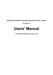
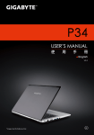
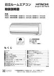
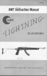
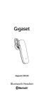
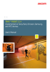
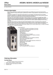
上海维宏电子科技股份有限公司
Weihong Electronic Technology Co., Ltd.
Current
file
folder path
Currently
selected file
File list
File extension
Fig. 4-39 Manager window
Right clicking in the Manager window, a shortcut menu will pop up, as illustrated below:
Fig. 4-40 Shortcut menu in Manager window

New
There are three ways to create a new machining file instantaneously:
One: select “File| New” (shortcut key: Ctrl+N);
Two: right click in the Manager window and select [New] from the pop-up shortcut menu;
Three: click
on the lower part of Manager window.
Then the system will automatically generate a new machining file “Untitle1.nc” and the user can
decide the save location of the new file.
Fig. 4-41 Save location
Click
to choose the save location.
In addition, the user can also edit, delete, rename or load the newly created file. Refer to the
contents below for detail.
In addition, the user can also open a processing file by choosing “file (F)| open and load (O)…”
from the menu.
Specialized, Concentrated, Focused
41
上海维宏电子科技股份有限公司
Weihong Electronic Technology Co., Ltd.

Edit
There are three ways to edit the selected machining file;
One: select “Edit| Edit the Selected File”;
Two: right click in the Manager window and then select “Edit” from the pop-up shortcut menu;
Three: click
on the lower part of Manager window.
And then the system will switch to the Editor window automatically. The user then can do editing
in this window. For details, refer to Editor Window.

Delete
There are three ways to delete the selected machining file:
One: select “Edit| Delete the Selected File”;
Two: right click in the Manager window and select “Delete” from the pop-up shortcut menu;
Three: click
on the lower part of Manager window.
A pop-up dialog box will ask the user whether to delete the selected machining file and whether
this file is being edited or processed.
Fig. 4-42 Delete a machining file
Click [Yes] to delete it.
Prompt:
The selected file in the file list box is highlighted (in blue).

Rename
There are three ways to rename the selected machining file:
One: select “Edit| Rename the Selected File”;
Two: right click in the Manager window and then select “Rename” from the pop-up shortcut
menu;
Three: click
on the lower part of Manager window.
Then the file name will be in edit state, as illustrated in Fig. 4-43:
42
Specialized, Concentrated, Focused
上海维宏电子科技股份有限公司
Weihong Electronic Technology Co., Ltd.
Fig. 4-43 Rename dialog box
After entering the file name, click “Enter” key or click on a blank area.

Load
There are five ways to load the selected machining file:
One: select “File| Open and Load”;
Two: right click on the Manager window and then select “Load” from the pop-up shortcut menu;
Three: click
Four: click
on the lower part of Manager window;
on the toolbar;
Five: right click in the Auto window and then select “Open and Load” from the pop-up shortcut
menu.
4.14. Editor Window
On the top of this window are the file name being edited and its path, as shown in Fig. 4-44.
Fig. 4-44 Editor window
It can edit a machining file with a size bigger than 1000M byte (1 G) and thus can fulfill editing
requirements of any complex machining file.
Right clicking in the Editor window will eject a shortcut menu for option.
Notice: it is not recommended to edit a file with saved workpiece origin.
Specialized, Concentrated, Focused
43
上海维宏电子科技股份有限公司
Weihong Electronic Technology Co., Ltd.
4.15. I/O State Window
The I/O State window displays the current state of system I/O ports and is very helpful for
system monitoring and breakdown diagnosis.
Caution:
The contents displayed in this window may vary with configuration, control card and requirements of the user.
The information provided here is for reference only.
The icons in the front of the ports indicate:
: Green filled dot means that there is signal input in this port;
: Red filled dot means that there is no signal input in this port;
: Green hollow dot means that there is signal output in this port;
: Red hollow dot means that there is no signal output in this port.
Fig. 4-45 I/O State window
44
Specialized, Concentrated, Focused
上海维宏电子科技股份有限公司
Weihong Electronic Technology Co., Ltd.
5. NcStudio Menu System
5.1. "File" Menu
This menu includes many options, like “Open and Load”, “Unload”, “New”, as following.

Open and Load
Shortcut key: Ctrl + O. The menu is used for opening a processing file on the hard disk. Clicking
the menu item, the system will eject "Open and Load" dialog box, as shown below.
Fig. 5-1 Open and load dialog box
Clicking the drop-down button in
can call the
processing files under other routes. After selecting the file, click “Open”, the name of the file
displayed on the title bar.

Unload
It is used to unload the current machining file.

New
It is used to create a new machining file.
After selecting this option, “Editor” window is switched to for file editing. After edit, right click and
select “Save” from the pop-up shortcut menu.

Open and Edit
It is used to open an existing machining file and switch to the Editor window to edit it.

Edit Loaded File
It is used to edit the currently loaded machining file.
Specialized, Concentrated, Focused
45
上海维宏电子科技股份有限公司
Weihong Electronic Technology Co., Ltd.

Save
It is used to save the machining file after editing.

Save as
It is used to resave the current machining file in the Editor window.
Fig. 5-2 “Save As” dialog

Save and Load
It is used to save and load the current machining file in the Editor window as the currently
loaded machining file.

Close
It is used to close the machining file being edited.

Config
Fig. 5-3 Configuration options
Notice: the configuration is set by the machine tool builder, and the user is not entitled to change it. Otherwise,
the machine tool cannot work properly.

Recent Loaded File
This menu item includes a new submenu, displaying the recently loaded machining files. The
user can re-load them quickly with this function.
46
Specialized, Concentrated, Focused
上海维宏电子科技股份有限公司
Weihong Electronic Technology Co., Ltd.

Recent Edited File
This menu item includes a new submenu, displaying the recently edited machining files. The
user can re-edit them quickly with this function.

Exit
It is used to close the NcStudio system, invalid in machining state.
5.2. "Edit" Menu
The items in “Edit” menu change with the currently active window in the second window area
(including Trace window, Log window, Manager window, Editor window and I/O State window).

Array Machining
This function allows executing array machining on one machining file. Clicking this item, a
dialog box will pop up, as illustrated below:
Fig. 5-4 Array machining dialog
Click
and select the machining file for array.
After setting the correct columns, rows, row space (as R in the above figure) and column space
(as C in the above figure), click [Generate G-File]. And then the newly generated machining file will
be loaded to NcStudio automatically.
G codes like G65 and G92 are not supported in array function, neither are subroutines. If they appear in the
machining file, the system will prompt to delete them automatically or manually.
To set different row spaces and column spaces, click [Advance], a dialog box ejected, as below.
Specialized, Concentrated, Focused
47
上海维宏电子科技股份有限公司
Weihong Electronic Technology Co., Ltd.
Fig. 5-5 Array machining
“Fresh” is used to update the “Row space list” and “Col. space list” in “Advance” mode after
entering the values of “Rows” and “Columns”. Then the user can manually set different row/column
spaces in these two lists.

Mirror Rotate Machining Setting
This function can conduct mirror and rotation on a machining file. Choosing this menu item, a
dialog box will pop up, as shown in Fig. 5-6.
48
Specialized, Concentrated, Focused
上海维宏电子科技股份有限公司
Weihong Electronic Technology Co., Ltd.
Fig. 5-6 Mirror & rotation machining
After selecting one of the above options and clicking [OK], the newly-generated machining file
will be loaded into NcStudio automatically.
5.3. "View" Menu
The items in “View” menu change with the currently active window in the second window area
(including Trace window, Log window, Manager window, Editor window and I/O State window).
5.3.1.
“View” Menu When Manger, Editor or I/O State Window
Activated
Fig. 5-7 “View” menu 1

Show File Line Number
This function displays/conceals the row number of instructions in the Auto window, only
available when the Auto window is activated.
Specialized, Concentrated, Focused
49
上海维宏电子科技股份有限公司
Weihong Electronic Technology Co., Ltd.

Trace Current Line
The function traces the row number of current instruction in the Auto window during processing.

File Information
Clicking [File Information], a dialog box will pop up, as illustrated below.
Fig. 5-8 Statistics of machining file
The dialog box displays the statistic information of machining file during auto processing, such
as total, machining range, etc. Combining with simulation function, the user can learn various
information of machining file quickly and rapidly.

Total Time
Displays the total time of machining and cutting time.

Motion Range
The max. and min. workpiece coordinates of machine tool movement in machining.

50
Machining Range
Specialized, Concentrated, Focused
上海维宏电子科技股份有限公司
Weihong Electronic Technology Co., Ltd.
The max. and min. workpiece coordinates of machine tool in actual cutting.
5.3.2.
“View” Menu When Trace Window Activated
Fig. 5-9 “View” menu 2
Refer to chapter 4.11. Trace window for details of the above submenus.
5.3.3.
“View” Menu When Log Window Activated
Fig. 5-10 “View” menu 3
Refer to chapter 4.12 Log Window for details of the above submenus.
5.4. "Operation" Menu
“Operation” menu includes many items, such as “Single Block”, “Handwheel Gear”, “Set
Offsets”, etc, which will be introduced separately in the following.
Specialized, Concentrated, Focused
51
上海维宏电子科技股份有限公司
Weihong Electronic Technology Co., Ltd.

Single Block
Under Single Block mode, the system will enter into Pause state when the motion speed
becomes 0. To resume machining, the user needs to click
(Start). The system will enter into
Pause state again when the speed becomes 0 again. That is to say, Pause state will be entered into
after the completion of a block, to resume machining, the user needs to click “Start”.
The user can choose this function before or during processing since it is helpful for error
diagnosing and failure recovery.

Handwheel Gear
When “Handwheel Gear” is selected under Auto mode, clicking
, the system will implement
the machining file with the turning of handwheel. When the handwheel is stopped turning, machining
will also stop. The machining speed changes with the turning speed of handwheel.
The user can choose this function before machining and this will help him judge whether the
machining file is correct.

Set Offsets
Right clicking in any part of NC State Widow can also call this function. Its dialog is as shown in
Fig. 5-11.
Fig. 5-11 Set offset
52
Specialized, Concentrated, Focused
上海维宏电子科技股份有限公司
Weihong Electronic Technology Co., Ltd.

Public Offset
Also called external offset. It is used to record the temporary adjustment value of workpiece
origin. As it can only be adjusted manually and will not be changed during the execution of any auto
function, the value will not be changed during fixed presetting and mobile presetting. For example, if
the value is not 0 before presetting, the workpiece coordinate will not be 0 either when presetting
completes. The following buttons can be used to modify the value of Z public offset.
Fig. 5-12 Buttons to modify Z public offset
Clicking one of the above buttons, the Z workpiece origin will move up or down a specified
distance to form a new workpiece coordinate system; clicking the button repeatedly, the Z workpiece
origin will move a distance accumulated.

Workpiece Offset
The offset of workpiece origin with respect to machine origin. See Fig. 5-13.
Fig. 5-13 Workpiece offset
It displays the machine coordinates of workpiece origin. Manually entering values can be used
to set the machine coordinates of workpiece origin, though not recommended.

Workpiece Coordinate
Displaying the workpiece coordinates of current cut point. See below.
Fig. 5-14 Workpiece coordinate
The following buttons can be used to clear X/Y workpiece coordinate, as shown below.
Specialized, Concentrated, Focused
53
上海维宏电子科技股份有限公司
Weihong Electronic Technology Co., Ltd.
Fig. 5-15 Workpiece coordinate clear
Workpiece coordinate= Machine coordinate- Public offset- Workpiece offset- Tool position offset

Workpiece Surface
The below two buttons are used for auto measure or manually setting current coordinate as Z
workpiece origin in floating presetting. See Fig. 5-16.
Fig. 5-16 Workpiece surface

Record and Center Division
Fig. 5-17 Record and center division
The above buttons are used to get the intermediate point of two points. The method is: first,
move the tool to the first target point and then click [Record X], the system recording the X machine
coordinate of this point. Secondly, move the tool to the second target point and then click [Center
Division X], the system automatically working out the X machine coordinate of the intermediate point.
The method to get Y coordinate of intermediate point is similar.

Move to Workpiece Origin
After this function is executed, if the tool nose is below the safe height, the Z axis will move up
to the safe height first and then the X axis and Y axis will move to the workpiece origin together; if
the tool nose is above the safe height, the X axis and Y axis will move to the workpiece origin
together first and then the Z axis will move down to the safe height.
54
Specialized, Concentrated, Focused
上海维宏电子科技股份有限公司
Weihong Electronic Technology Co., Ltd.
The user can also execute this function by clicking

on the toolbar.
Save the Current Workpiece Origin
This function saves the current workpiece origin as well as the name of the file and the machine
coordinates of current point into NcStudio, so that the saved workpiece origin can be easily found
later. 10 groups of data can be saved at most. See Fig. 5-18.
Fig. 5-18 Save the current workpiece origin

Load the Saved Workpiece Origin
It is used to load the coordinate value of the saved workpiece origin.

Start
Clicking [Start], the system will enter into auto processing mode. If the system is under
simulation state, it will execute machining file under simulation mode.
This function can also be executed by clicking

on the toolbar.
Pause
During auto processing, selecting [Pause], the system will suspend processing and raise the
cutter to enter into “Auto| Pause” state. To resume processing, choose [Start].
When simulating, choosing [Pause], the system will suspend simulation and enter into “Auto|
Pause” state. To resume simulation, choose [Start]
The function can also be executed by clicking

on the toolbar.
Stop
During auto processing, choosing [Stop], the machine tool will cease processing and raise the
cutter to enter into “Auto| Idle” state. This is the normal way to stop when processing.
When simulating, choosing [Stop], the system will suspend simulation and enter into “Auto| Idle”
state. To start or resume simulation, choose [Start], [Advanced Start] or [Breakpoint Resume], etc.
Specialized, Concentrated, Focused
55
上海维宏电子科技股份有限公司
Weihong Electronic Technology Co., Ltd.
The function can also be executed by clicking

on the toolbar.
Enter Simulation Mode then Start Simulating
By selecting this menu item, the machine tool will conduct high-speed simulation from the
beginning of the machining file, providing a high-speed but vivid simulative processing environment.
Under simulation mode, the system doesn‟t command the machine tool to do the corresponding
mechanical movement, but shows the tool path in the Trace window at a high speed. Through
simulation, apart from other appended information, the user can be informed of the machine tool‟s
movement path in advance and thus avoid equipment damage caused by programming errors.
Once simulation starts, this menu item will change into” Stop Simulating then Leave Simulation
Mode”. Clicking it, the system will stop simulating and exit from the simulation mode immediately.
This function can also be executed by clicking

on the toolbar.
Advanced Start
Clicking this menu item, an “Execute (Advanced Options)” dialog box will pop up, as illustrated
in Fig. 5-19.
Fig. 5-19 Advanced start
This function allows selecting any blocks for machining. The user can choose the processing
56
Specialized, Concentrated, Focused
上海维宏电子科技股份有限公司
Weihong Electronic Technology Co., Ltd.
range in the dialog box according to the type of machining file.
Note: if the file loaded is a G code file, only “Specify the range according to the row number” is available, the
other two options are unavailable.
If the file loaded is an ENG file, the three options are all available.

Select Tool
It is a function specified for an ENG file. In addition, to enable this function, the parameter
“N4093 MachiningEngFileByToolNumber” should be set as “true” first.

Resume
Clicking this menu item, the system will automatically resume processing from the row number
stopped last time.
In case of sudden power failure, E-stop, etc, this function (breakpoint resume) can be executed
to make the machine tool quickly move to the breakpoint and resume processing, which will save
considerable machining time.
This function can also be executed by clicking

on the toolbar.
Advanced MDI
Clicking this menu item, an “Advanced Functions” dialog box will pop up, as shown in Fig. 5-20,
including 5 function windows, which are [Rectangle Mill], [Round Mill], [Rectangle Frame Mill],
[Round Frame Mill] and [MDI]. Bottom milling and frame milling can be completed in the first four
windows simply by entering the values of relevant parameters (“Inner” and “Outer” are used to
specify whether milling the inner part of the frame or outer part).
Specialized, Concentrated, Focused
57
上海维宏电子科技股份有限公司
Weihong Electronic Technology Co., Ltd.
Fig. 5-20 Rectangle bottom milling window
See Fig. 5-21. After entering standard instructions (like G codes, T codes and M Codes, etc)
into the edit box of “MDI” window, click “Execute”, the system executing the entered instructions
instantly. In addition, instructions entered previously are recorded in the window for inquiring. If
multiple instructions are entered at one time, “;” is used to separate them from each other. When the
instructions are not entered properly, NcStudio will give out a prompt.
If the box before “Show this dialog-box while running” at the bottom is checked, this dialog can
still be seen when executing the instructions, for the convenience of rapidly setting relevant
parameters of booting milling and frame milling or entering standard instructions.
Fig. 5-21 MDI window
58
Specialized, Concentrated, Focused
上海维宏电子科技股份有限公司
Weihong Electronic Technology Co., Ltd.

Jiggle
This function is for fine tuning without stopping machining, only available during auto processing
or in the PAUSE state. See Fig. 5-22.
The result of jiggle will only have an effect on the current machining task. It will become invalid
when [Start] or [Resume] is executed after [Stop].
Fig. 5-22 Jiggle dialog box

Mobile Calibrator
Choosing this menu item will eject a dialog box, as shown below.
Fig. 5-23 Tool presetting
Choosing “Yes” will execute tool presetting. Refer to chapter 4.9.1 Calibrate the Workpiece
Surface for detail.
Choosing “No” will cancel tool presetting.

Fixed Calibrator
Choosing this menu item will eject a dialog box, as illustrated below.
Specialized, Concentrated, Focused
59
上海维宏电子科技股份有限公司
Weihong Electronic Technology Co., Ltd.
Fig. 5-24 Fixed presetting
Refer to chapter 4.9.3 Fixed Presetting for details. “The recent value” in the above picture is
entered automatically by NcStudio.

Back to Mechanical Origin
Also called go home, back to machine origin and back to reference point. Selecting this menu
will eject a dialog box, as shown in Fig. 5-25.
Fig. 5-25 Back to mechanical origin

60
[All Axes]: all the axes will go home successively (Z axis first and then X and Y axes.).
Specialized, Concentrated, Focused
上海维宏电子科技股份有限公司
Weihong Electronic Technology Co., Ltd.

[Setting Directly]: directly setting current machine coordinates as correct ones. Before executing
this function, the user must confirm that the current X, Y, Z coordinates are right machine
coordinates. If the machine tool was turned off or underwent an E-stop before, it is not
recommended to execute this function.

[X Axis], [Y Axis] and [Z Axis]: homing the corresponding axis alone.
Fig. 5-26 NC state window
After all the axes have returned to machine origin, a mark “ ” will appear before each axis in the
NC state window.

Back to Fixed Point
The machine tool will move to the fixed point (machine coordinates) automatically when this
menu item is selected. The machine coordinates of fixed point should be set in a position facilitating
fast tool change and workpiece replacement.
The machine coordinates of fixed point are determined by parameters [N4210], [N4211] and
[N4212].

Disable Mechanical Limits
See Fig. 5-27. In case of hard limit alarm, execute this function. The system will disable limit
function and remove the alarm. At this time, move the machine tool away from the limit switch to a
normal position via the manual buttons in the Manual window.
Fig. 5-27 Disable mechanical limits
Caution: pay attention to the direction when moving the machine tool away from the limit switch to a normal
position, or the machine tool may be damaged!
Specialized, Concentrated, Focused
61
上海维宏电子科技股份有限公司
Weihong Electronic Technology Co., Ltd.

Alarm Reset
When an alarm pops up, executing this function will restore the system to the “Idle” state.

Scan Function
Clicking this menu item, a dialog will pop up, as shown in Fig. 5-28.
Fig. 5-28 Scan hole position
This function is mainly for punching. Manually move to the target position (XY), then click “Note”
to record the workpiece coordinates, then to the next target position, then record…When finished,
click “”Save As” to generate a machining file. Since the generated file cannot be loaded into the
system automatically, the user needs to load it into NcStudio before machining.

[Position of REFFER Plane]: a plane from rapid traverse rate to punching speed.

Parameter Restore
NcStudio can backup parameters automatically. Choosing this option, a dialog box will pop up,
as illustrated below.
62
Specialized, Concentrated, Focused
上海维宏电子科技股份有限公司
Weihong Electronic Technology Co., Ltd.
Fig. 5-29 Parameters auto backup
The system provides six kinds of parameter backups: “last parameter setting”, “parameter
setting yesterday”, “parameter setting 2 days ago”, “parameter setting 5 days ago”, “parameter
setting 10 days ago” and “parameter setting of OEM setting”. The user can select one of them
according to actual situations.
After one of them is selected, NcStudio will exit automatically. At this time, the user needs to
re-open it manually.

Set Parameters
It is used to open the parameter window to set parameters. Refer to Chapter 6.3 for details.
5.5. “Machine” Menu
“Machine” menu includes menu items like “Turn on Spindle”, “Turn on Coolant”, “Turn on Light”
and “Modify Tool No.”, etc, as following.

Turn on Spindle
It is used to control spindle ON/ OFF.

Turn on Coolant
It is used to control coolant pump ON/ OFF.

Turn on Light
It is used to control lamp ON/ OFF.
Specialized, Concentrated, Focused
63
上海维宏电子科技股份有限公司
Weihong Electronic Technology Co., Ltd.

Modify Tool No.
This item is used to uniform the current tool No. displayed with the tool No. to be used so that
the system can place the current tool to the correct position in the tool magazine or call the right tool
from the correct position in the tool magazine, mainly used in tool change.
Fig. 5-30 Modify tool number

Feedrate
The feedrate can be 0%, 10%, 20%, 50%, 90%, 100%, and 120%, function similar to “Feedrate”
slider block in the “NC State” window. For details, refer to Sliding Block of Feedrate Override in
chapter 4.6.2.

Efficiency/Quality Adjustment
Clicking the option, a dialog box will pop up, as illustrated below:
Fig. 5-31 Efficiency – Quality adjustment
Quality and efficiency relates to each other negatively. Giving priority to quality will lead to high
processing quality while to speed will result in high processing efficiency.
5.6. "Window" Menu
“Window” menu is consisted of multiple options, such as “Show Auto Window”, “Show Manu
Window”, “Show Calibration Window” and “Show Trace Window”, and so on, mainly used to rapidly
turn to a window.
5.7. "Help" Menu
“Help” menu includes the following menu items.
64
Specialized, Concentrated, Focused
上海维宏电子科技股份有限公司
Weihong Electronic Technology Co., Ltd.

Tip of the Day
Selecting this option, a dialog box will pop up, as illustrated below, telling information and
operation of NcStudio.
Fig. 5-32 Daily tip

Keyboard Map
Choosing this item, a dialog box will pop up, displaying shortcut key information of NcStudio.
Fig. 5-33 Shortcut key list window

About NcStudio
Choosing this menu item, a dialog box will pop up, telling information about NcStudio version
No., control card model number and system registration, etc.
Specialized, Concentrated, Focused
65
上海维宏电子科技股份有限公司
Weihong Electronic Technology Co., Ltd.
Version No.
2. Click here to open
Register dialog
Control Card
Card ID, changes with
registered times
1. Control Card No, send it to
his manufacturer to get a
registration code
Remaining usage time
Fig. 5-34 “About NcStudio”
In the above dialog, the user can view such info as version, control card, manufacturer, etc.
Register function is used for limiting the system usage time. When the usage time is used out,
the user can write down the Control Card No. and send it to his manufacturer to get a registration
code. Then click on the button [Register…] to eject registration code input box, as shown in Fig. 5-35.
And then input the received code into the following dialog, and click “OK” to finish register.
Input the received code from the
manufacturer here.
Fig. 5-35 Input register
Note: Card ID changes with registered times, reflected in the last three numbers of Control Card No.. When
registered times is 0, the last three numbers are 000; when 1, the last three numbers 001.
66
Specialized, Concentrated, Focused
上海维宏电子科技股份有限公司
Weihong Electronic Technology Co., Ltd.
6. Parameter Setup
Equipped with abundant machining parameters, NcStudio is competent for various machining
tasks. This chapter will introduce operator‟s parameters only. For manufacture‟s parameters, refer to
Manufacturer’s Manual for detail.
Parameters in NcStudio can also be divided into the following categories: opera parameters,
axes parameters, spindle/H.W. parameters, I/O address parameters, compensation parameters, ref.
parameters, cutter parameters, other parameters and all parameters.
6.1. Parameter Modification Permission
The parameters viewed vary with privilege. To access manufacture‟s parameters, password
“ncstudio” is needed.
Fig. 6-1 Parameter permission
If there is a need to change the password, click “Change Password” to eject the “Change
Password” dialog, as shown below. After entering the old password and new password correctly,
click “OK” to validate the new password.
Fig. 6-2 Change password dialog
6.2. Parameter Modification Method
To modify a parameter, double-click on the row where the parameter lies and then enter the
data into the pop-up dialog box.
For “True/False” type of parameters, inputting “1” indicates “True” while “0” “False”. The user
can also directly input “True” or “False”.
Prompt: no parameters can be modified in machining.
Specialized, Concentrated, Focused
67
上海维宏电子科技股份有限公司
Weihong Electronic Technology Co., Ltd.
6.3. Operator’s Parameters
No.
Name
Setting Range
Default
When Enabled
Opera parameters
NormalJogFeedrate
N4025
N4260
Immediately
The moving speed of machine tool in manual mode when the feedrate override is 100%.
The manual moving speed varies with the feedrate override.
RapidJogFeedrate
N4026
1800
0~100000(mm/min)
2400
0~100000(mm/min)
Immediately
The speed of machine tool when one of the manual buttons and acceleration button
(number key 0) are pressed simultaneously at 100% feedrate override.
MaxJogFeedrateBefore
BKREF
0~100000(mm/min)
1200
Immediately
3000
Immediately
1500
Immediately
0
Immediately
The max. speed in jog mode before homing.
N4031
N4032
N4034
RapidTravelFeedrate
0~100000(mm/min)
The default positioning speed (instead of machining speed).
DefaultFeedrate
0~100000(mm/min)
The default machining speed (instead of positioning speed).
UseDefaultFeedrate
0: Not use
1: Use
If it is set as “1”, the speed specified in the machining file will become invalid.
N4035
UseDefaultSpindleRev
0: Not use
1: Use
0
Immediately
If it is set as “1”, the spindle speed specified in the machining file will become invalid.
PauseDownSpeed
N4027
N4028
N4049
0~100000(mm/min)
600
Immediately
Plunge rate of Z axis (backing to the cutting point before pause) in continuous machining
after pause.
PauseUpSpeed
0~100000(mm/min)
600
Immediately
100
Immediately
10
Immediately
Tool lifting speed of Z axis at pause.
ToolRasingHWorkCoor
OnPause
0~9999(mm)
The pause position of Z axis in machining.
N4050
ToolRasingHeightOnPa
use
0~500(mm)
The lifting height of Z axis at pause with respect to cutting point.
FixedCalibratorBlockPo
sition (X/Y/Z)
N4200
~
N4202
68
-99999~99999(mm)
X: 0 Y: 0
Z: -1
Immediately
X/Y: machine coordinates of X and Y when the tool nose reaching the range of tool
presetting (the nearer to central point, the better).
Z: machine coordinate of Z axis when the tool nose arriving at a certain height above the
surface of tool presetter (running at G00 speed above this height while at presetting speed
below this height).
Specialized, Concentrated, Focused
上海维宏电子科技股份有限公司
Weihong Electronic Technology Co., Ltd.
No.
N4006
N4007
Name
G73_G83SafeHeight
Setting Range
-99999~99999(mm)
Default
0
When Enabled
Immediately
Specifying the retract distance after each feed in the G73_G83 cycle drilling command.
DirectionWhileFixedDrill
Stop
0: +X; 1: -X; 2: +Y; 3: -Y
0
Immediately
1
Immediately
Only valid in X-Y plane (G17).
IJKIncrementModeValid
N4063
0: the coordinates of circle center are with respect to workpiece origin.
1: the coordinates of circle center are with respect to the start point of machining arc.
NeedConfirmClearWC
N1002
N4029
N4030
N4045
JiggleFeedrate
N4210
Immediately
0: Keep still; 1: Back to fixed
point; 2: Back to workpiece
origin
0
Immediately
0~100000(mm/min)
60
Immediately
0.01~0.5(mm)
0.01
Immediately
0
Immediately
The speed in jiggle.
JiggleStepLength
The moving distance of machine tool in each jiggle.
0~3
0: No special treatment; parameter “N4045” is invalid.
1: N4045 enabled when only Z axis moves downward; feeding speed is decided by
parameter N4045 when set as 1.
2: N4045 enabled when Z-axis downward movement included; when the Z axis moves
downward (no matter whether X axis and Y axis moves or not), feeding speed is decided
by N4045.
3: Slowly regulate feed speed.
Z_DownFeedrate
0~100000(mm/min)
480
Immediately
10
Immediately
Enabled when parameter N4044 set as “1” or “2”.
SafeHeight
N4051
1
0: Keep still; after machining ends normally, the spindle remains in the stop position.
1: Back to fixed point; after machining ends normally, the machine tool will go to the
position set by parameters “N4210”, “N4211” and “N4212” (machine coordinates)
automatically.
2: Back to workpiece origin; after machining ends normally, the machine tool will return to
the current workpiece origin automatically.
ZDownFeedrateOption
N4044
0: Invalid
1: Valid
Whether to give a prompt when clearing current workpiece coordinates, i.e. setting current
point as workpiece origin, in order to avoid misoperation.
ActionAfterProgrammin
g
N4005
0: Invalid
1: Valid
0.001~1000(mm)
Calculated with respect to workpiece origin; the system regards it is safe to move
horizontally at this height; mainly used in “back to workpiece origin” and “breakpoint
resume”.
FixedPointPosition
Specialized, Concentrated, Focused
-99999~99999(mm)
0
Immediately
69
上海维宏电子科技股份有限公司
Weihong Electronic Technology Co., Ltd.
No.
~
N4212
Name
Setting Range
Default
When Enabled
(X/Y/Z)
The machine coordinates of fixed point; used together with parameter N4005.
PLTFileTranslatingParameters
N4070
SafeHeightAtG00Feedr
ate
1
0~99999(mm/min)
After re-loading
The tool lifting height of Z axis in rapid traverse when machining a PLT file.
N4071
N4072
N4073
PLTUnit
0.001~99999(mm/plu)
10
After re-loading
PLTToolsDistanceWhile
ProcessArea
0.001~99999(mm)
0.025
After re-loading
The ToolsDistance (tool space) should be smaller than tool diameter when machining a
PLT file.
TwoDimensionalFileDep
th
-99999~0(mm)
-1
After re-loading
1
After re-loading
The machining depth of 2D PLT file.
DxfFileTranslatingParameters
N4080
SafeHeightAtG00Feedr
ate
0~99999(mm/min)
The tool lifting height of Z axis in rapid traverse when machining a DXF file.
N4081
TwoDimensionalFileDep
th
-1
After re-loading
0~1
0
After re-loading
-99999~0(mm)
-1
After re-loading
1
After re-loading
-99999~0(mm)
The machining depth of 2D DXF file.
N4082
N4083
TheSourceOfMachineD
epth
0: From parameter
1: From DXF file
DepthDelta
The machining depth of 2D file each time in layer machining.
UseFirstPointAsOriginIn
DXFFiles
N4084
N4085
0: Invalid
1: Valid
0: set the origin in the DXF file as workpiece origin
1: set a user-defined point in the DXF file as workpiece origin. For instance, when drawing
a picture in CAD, draw a point (better near or inside the picture). The system will treat this
point as workpiece origin and not process it. If there are several points in the DXF file, the
first drawn point will be set as workpiece origin.
EnableMachineDividuall
y
0: Invalid
1: Valid
0
After re-loading
If set as “1”, the system will not process the next shape until finishing current one.
N4086
MethodForDrillingDXFFi
les
0~1
0
After re-loading
Hole machining mode in machining a DXF file. 0: Once done; 1: Reciprocating chip
70
Specialized, Concentrated, Focused
上海维宏电子科技股份有限公司
Weihong Electronic Technology Co., Ltd.
No.
Name
Setting Range
Default
When Enabled
removal
N4087
EachDepthForPolyDrill
0~99999(mm)
0.5
After re-loading
1
After re-loading
Each drilling depth in reciprocating chip removal mode.
ENGFileTranslatingParameter
N4090
SafeHeightAtG00Feedr
ate
0~99999(mm/min)
The tool lifting height of Z axis in rapid traverse when machining an ENG file.
N4091
N4093
N4094
PauseAndPromptWhile
ChangeTools
0~1
1
After re-loading
Whether to pause and prompt tool change when it is time for tool change when machining
an ENG file. 0: Pause but not prompt; 1: Pause and prompt
MachiningEngFileByToo
lNumber
0
After re-loading
When set as “1”, machining will be executed in terms of the specified tool number, and only
the machining file corresponding to this tool will be processed.
PauseTimeAfterEachCy
cle
0~99999(ms)
0
After re-loading
0
After re-loading
The dwell time after each cycle in ENG file machining.
N4095
N4096
N4097
N4129
DeepHoleMachiningWa
y
0~1
Deep hole machining mode. 0: Reciprocating chip removal; 1: High-speed reciprocating
chip removal
RETRACT_VALUE
0~99999(mm)
1
After re-loading
Retract distance after each feed in high-speed reciprocating chip removal mode.
MachiningEngFileModif
yToolNumber
0: Invalid
1: Valid
0
After re-loading
MachiningGFileByToolN
umber
0: Invalid
1: Valid
0
After re-loading
Whether to execute machining according to the specified tool number.
Z_Axis_Stop_Options
N8020
N8021
0~2
0
Immediately
The position of Z axis at pause. 0: To raise a given distance; 1: To specified workpiece
coordinate; 2: To specified machine coordinate
Z_Axis_Stop_Pos_in_M
CS
-350~0
0
Immediately
The machine coordinate of Z axis at pause, available when parameter N8020 is set as “2”.
N8022
SwitchAxisSafePrompt
0: Invalid
1: Valid
1
Immediately
0: Invalid
1: Valid
0
Immediately
Axes parameters
N1150
~
CheckWorkCoordinateR
ange (X/Y/Z)
Specialized, Concentrated, Focused
71
上海维宏电子科技股份有限公司
Weihong Electronic Technology Co., Ltd.
No.
Name
Setting Range
Default
When Enabled
N1152
If set as “1”, the system will check whether machining is within the workpiece coordinate
range (upper limit and lower limit).
N1160
~
N1162
WorkCoordinateLowerLi
mit (X/Y/Z)
N1170
~
N1172
WorkCoordinateUpperLi
mit (X/Y/Z)
-99999~99999(mm)
-10000
Immediately
10000
Immediately
1
Immediately
1
Immediately
0
Immediately
0
Immediately
The lower limit of workpiece coordinate in each axis.
-99999~99999(mm)
The upper limit of workpiece coordinate in each axis.
Spindle/H.W. parameters
N0004
StopSpindleWhenFinish
0: Invalid
1: Valid
Whether the spindle stops rotating when machining stops.
N0005
StopSpindleWhilePause
Stop
0: Invalid
1: Valid
Whether spindle stops rotating when machining pauses.
Compensation parameters
N3004
CutterCompensationVali
d
0: Invalid
1: Valid
Whether to enable tool compensation.
CUTTER_COMPENSA
TION_DIRECTION
0~2
Specifying the direction of tool compensation. 0: No tool compensation; 1: Left tool
compensation; 2: Right tool compensation
Right Compensation along
Tool Moving Direction
Tool Rotary Direction
Tool Moving Direction
N3004
Tool Moving Direction
Offset
Tool Rotary Direction
Offset
Left Tool Compensation
Left Compensation along
Tool Moving Direction
Right Tool Compensation
Ref. parameters
N2001
MoveToMechanicalPoin
tBeforeMachining
0: Invalid
1: Valid
1
Immediately
When set as “1”, homing will be prompted and must be executed before each machining.
when “0”, the system will not give a prompt and can execute machining directly.
Cutter parameters
N14900
72
MobileCalibratorBlockT
hickness
0~10000(mm)
20
Immediately
Specialized, Concentrated, Focused
上海维宏电子科技股份有限公司
Weihong Electronic Technology Co., Ltd.
No.
Name
Setting Range
Default
When Enabled
The max. tool length.
N14901
N15021
N15022
N15023
N15024
N15030
~
N15032
ToleranceOfToolBroken
0.5
Immediately
(mm)
0
Immediately
(mm)
0
Immediately
(mm)
0
Immediately
(mm)
0
Immediately
0
Immediately
0
After restart
0~100(mm)
The allowable tolerance when checking broken tools.
Diameter
Tool diameter.
Length
Tool length.
DiameterFray
Wear loss of tool diameter.
LengthFray
Wear loss of tool length.
CutterPositionOffset
(X/Y/Z)
The offset between current tool and the first tool.
Other parameters
N7003
AutoBackToZero
0: Invalid
1: Valid
Whether to go home automatically after starting the system each time.
N7017
N7312
MachTaskEndInformTyp
e
0~2
0
Immediately
0: Red light off; 1: Red light on for 3s; 2: Red light on until there is mouse or keyboard
input , then yellow light on
DelayTimeForCloseAirV
alve
0~100000(ms)
1000
Immediately
The delay time for tool change.
Specialized, Concentrated, Focused
73
上海维宏电子科技股份有限公司
Weihong Electronic Technology Co., Ltd.
7. Operation Steps
After installing the control card and software according to chapter 2.2.1 and 2.2.2, the system is
ready for use and can be opened. Then load a machining file and start debugging & commissioning.
7.1. Starting-up
Before starting the computer, make sure that the machine tool has been well connected to the
computer properly. Then power on the machine tool and computer. Then open NcStudio.
7.2. Machine Reset (Optional)
This operation is provided for machine tools with the function of backing to machine origin.
For machine tools supporting “back to machine origin” function, choosing “back to mechanical
origin” menu item will command the machine tool to return to the mechanical origin automatically
and adjust the coordinate system.
As NcStudio will save the current coordinates if it exits normally, so under certain circumstances,
such as after normal system shutdown, there is no need to “back to mechanical origin” before
resuming machining after re-opening the system.
Additionally, this operation can also be skipped if the user is sure about the accuracy of current
coordinates.
7.3. Load Machining File
Generally speaking, a machining file has to be loaded before machining begins. Otherwise,
some functions related with auto-processing will be unavailable.
Select [Open & Load] from [File] to eject a dialog box, and then choose the file to be processed.
After clicking [Open], the machining file will be loaded into the system automatically. At this time,
the user can press “CTRL+1” to switch to “Auto” window, where the user can view the current
machining file.
7.4. Manual Operation
After switching to [Manual] window, the number keys on the keyboard can be used to operate
the machine tool manually to check whether the direction of each axis is right.
The correlation is as follows:
74
6
Positive direction of X axis
4
Negative direction of X axis
Specialized, Concentrated, Focused
上海维宏电子科技股份有限公司
Weihong Electronic Technology Co., Ltd.
8
Positive direction of Y axis
2
Negative direction of Y axis
9
Positive direction of Z axis
1
Negative direction of Z axis
Pressing any one of the above keys and the number key 0 simultaneously will command the
machine tool to move at rapid jog speed.
7.5. Set Workpiece Origin
The workpiece origin is defined as the coordinate origin of X, Y and Z in the machining file.
Before machining starts, the workpiece origin should be fixed first. The steps are:
Manually move X axis and Y axis to the intended workpiece origin position, and then clear the
coordinates of current position by clicking the “W.Coor.” buttons (X, Y) in the “NC State” window. The
system will then conduct machining with the current position as the workpiece origin.
Through the above steps the workpiece origin of X axis and Y axis are fixed. To set the
workpiece origin of Z axis, more precise operation is needed. Combined with machine tool hardware,
the system supports Z axis presetting (calibration) function.
After all these operations, the workpiece origin is confirmed.
7.6. Check Ports in I/O State Window
I/O state window displays ports that indicate the communication status between hardware and
software, used for system monitoring and fault diagnosis. For details, refer to chapter 4.15.
The method to modify the polarity of port: select the port (ports) to be modified polarity, then
press “Ctrl+Alt+Shift” and right click simultaneously, a dialog as follow pop-up, then select “Toggle
Polarity”. Modification to port polarity becomes valid after software restart.
Fig. 7-1 Select toggle polarity
7.7. Set Speed Parameters
7.7.1.
LinearAcceleration (N4053)
It is used to describe the acceleration / deceleration ability of a single axis, with unit mm/s2. The
Specialized, Concentrated, Focused
75
上海维宏电子科技股份有限公司
Weihong Electronic Technology Co., Ltd.
value is determined by the physical characteristic of machine tool, such as quality of movement part,
torque, resistance, cutting load of feed-motor, and so on. The larger the value is, the less time spent
in the process of acceleration / deceleration will be, and the higher the efficiency will be. Generally,
for servo motor systems, the value is between 400 and 1200. Set the value smaller at the beginning;
make the machine tool perform various typical movements for a period of time, and carefully
observe it; if there is no abnormal situation, increase the value gradually; otherwise, decrease the
value and reserve 50% ~ 100% insurance allowance.
7.7.2.
ConnectionAcceleration (N4054)
It is used to describe the acceleration/deceleration ability in synchronized motion of
multi-feed-axis, with unit mm/s2. The value limits the maximum speed of machine tool in circular
movement. The larger this value is, the higher the maximum allowable speed on circular movement
of machine tool will be. Generally, for servo motor systems, the value is between 1000 and 5000; for
heavy machine tools, the value should be smaller. Set the value smaller at the beginning; make the
machine tool perform various typical movements for a period of time, and carefully observe it; if
there is no abnormal situation, increase the value gradually; otherwise, decrease the value and
reserve 50% ~ 100% insurance allowance.
7.7.3.
ReferenceCircleMaxSpeed (N4058)
Maximum speed of reference circle (ReferenceCircleMaxSpeed) corresponds to arc speed limit
function. When a machine tool processes an arc, it will vibrate due to centripetal force. To reduce
this kind of vibration, the software limits machining speed during machining an arc in terms of
centripetal acceleration. Take default setting as an example, the maximum line velocity of the
reference circle (Diameter:10mm) is 1800mm/min.
The formula to calculate centripetal acceleration is as following:
a
v2
r
Among the formula, r  (10 / 2)mm ; v  1800 mm / min ;
Thus centripetal acceleration a can be calculated; when other arcs are processed, this
centripetal acceleration is the maximum allowable centripetal acceleration. Arc speed will be limited,
if it is too large causing centripetal acceleration larger than a calculated in this formula.
7.7.4.
MinSpeedInACircularMotion (N4059)
Minimum speed of reference circle (MinSpeedInACircularMotion) also corresponds to arc
76
Specialized, Concentrated, Focused
上海维宏电子科技股份有限公司
Weihong Electronic Technology Co., Ltd.
speed limit function. a calculated in the last chapter is not the only criterion for arc speed limit
function.
a
v2
r
According to the above formula, in processing an arc with small radius, the line speed will be
limited quite low caused by arc speed limit, which will be a waste of time. Therefore, the software
provides this parameter, which is the minimum speed for circular motion. However small the arc
radius is, the machining speed will not be smaller than the value of this parameter.
Usually, given the drive ability of servo motor, frication of machine assembly, and endurance
capacity of mechanical components, the maximum speed of the three axes in actual using can be
limited by modifying the manufacturer parameter “AxisMaxFeedrate” (N4250~N4252).
7.8. Execute Auto Machining
Auto machining means that the machine tool processes the loaded machining file automatically.

Start Auto Machining
Select [Operation| Start] or click
on the toolbar or press the shortcut key F9. The machine
tool will execute machining automatically from the first line of machining file.

Stop
During auto machining, selecting [Operation| Stop] or
on the toolbar or pressing the
shortcut key F11 will stop machining immediately. The system will then enter into “IDLE” state. This
is how to make the system stop in an accurate and orderly way and also the recommend one.
Note:
When high-speed smooth connection is adopted, the system will stop when the connection speed becomes 0.

Pause
During auto processing, to suspend processing, select [Operation| Pause] or click
on the
toolbar or press the shortcut key F10. The system will then suspend processing immediately. To
continue processing, choose [Operation| Start] or click

on the tool bar or press F9.
Advanced Start
Selecting [Advanced Start], a dialog box will pop up. Then select start and end row No.. Refer to
“Advanced Start” in chapter 5.4 “Operation” Menu for detail.
Specialized, Concentrated, Focused
77
上海维宏电子科技股份有限公司
Weihong Electronic Technology Co., Ltd.
8. Precautions in Operation
8.1. Precautions for Multi-Task Executing

It is recommended that the user should consider the computer memory and not open too many
windows at the same time.

For some application procedures, such as games, VCD player, etc, they might not run stably
and smoothly. They are likely to take excessive system resources like memory and CPU
time-slice during running and at last cause computer crash. Therefore, during processing, in
order to avoid processing interruption caused by system crash, it is recommended not to open
these procedures.
8.2. Precautions for Homing
Homing (backing to mechanical point/ reference point/ machine origin) process varies with the
requirements of different systems. For systems with a high requirement for precision, the process of
machine reset will take a long time. Pay attention to system state. Do not exit from the “Back To
Mechanical Origin” dialog until the system enters into “Idle” state. Otherwise, the “back to
mechanical origin” process will be artificially terminated instead of being normally finished.
If the “back to mechanical origin process” is terminated manually, the consequences will be:

As the limit (mechanical origin) signal is still on, port alarm may occur;

Inexact positioning may occur: the calibration function of “back to mechanical origin” is
damaged manually and as a result, the machine coordinates become inaccurate;

Soft limit function becomes ineffective: as the “back to mechanical origin” process has not been
finished, the system will regard the soft limit function as ineffective until “back to mechanical
origin” process is finished.
78
Specialized, Concentrated, Focused
上海维宏电子科技股份有限公司
Weihong Electronic Technology Co., Ltd.
9. Shortcut Key List
Shortcut Key
Function
Shortcut Key
Function
Global shortcut keys
ESC
Shift among windows
TAB
Shift among controls
Ctrl+2 /ScrollLock
Show manual window
Ctrl+1
Show auto window
Ctrl+F1
Switch to Z1
Ctrl+F2
Switch to Z2
Ctrl+F7
Floating presetting
Ctrl+F9
Advanced start
Ctrl+Home
Ctrl+TAB
Ctrl+Shift+F9
Go home
Ctrl+Enter
Switch among
windows
Execute
instructions
folding
machining
Ctrl+Del
Full screen
Clear trace window
Ctrl+A
Select all
Ctrl+C
Copy
Ctrl+E
Open and edit
Ctrl+F
Search
Ctrl+H
Replace
Ctrl+I
Show machining info
Ctrl+N
New
Ctrl+O
Open and load
Ctrl+P
Edit
Ctrl+S
Save
Ctrl+U
Unload
Ctrl+V
Paste
Ctrl+X
Cut
Ctrl+Z
Undo
ALT+1/F4
ALT+2
Show log window
ALT+3
Show manager window
ALT+4
Show editor window
ALT+5
Show I/O state window
Show trace window
F3
Find next
F5
Direct positioning
F6
Set
workpiece
coordinates of current
point
F7
Back to workpiece origin
F8
Enter (exit) simulation
F9
Start
Pause
F11
Stop
F10/Pause Break
F12
Shift+F7
Return to tool change
position
Shift+F6
Set as workpiece origin
Fixed presetting
Shift+F9
Breakpoint resume
Shortcut keys in manual window
ScrollLock
Activate manual window
4
X- (Jog and increment
mode)
6
X+ (Jog and increment
mode)
2
Y- (Jog and increment
mode)
8
Y+ (Jog and increment
mode)
1
Z- (Jog and increment
mode)
9
Z+ (Jog and increment
mode)
Shortcut keys in trace window
Specialized, Concentrated, Focused
79
上海维宏电子科技股份有限公司
Weihong Electronic Technology Co., Ltd.
Shortcut Key
Function
Function
Show current machining
point
Home
Center
End
+
Zoom in
-
Zoom out
*
Fit to window size
5
Front view
8
Top view
2
Bottom view
4
Left view
6
Right view
1
Southwest view
7
Northwest view
3
Southeast view
9
Northeast view
Alt+→ or Alt+←
Rotate around Z axis
Alt+PgUp/Alt+PgDn
Rotate around Y axis
80
Shortcut Key
Alt+↑ or Alt+↓
Rotate around X axis
Specialized, Concentrated, Focused
上海维宏电子科技股份有限公司
Weihong Electronic Technology Co., Ltd.
10. Software License Agreement
License:
Shanghai Weihong Electronic Technology Co., Ltd. (hereinafter referred to as Weihong
Company) grants you the right to use this software, for which you must guarantee that you will not
use, copy, revise, rent, or transfer this system or any part of this system for any other purposes
beyond clauses made in this agreement.
You must guarantee:
1.
You use this system only on one set of equipment;
2.
You make read-only copy of this system only for backup or file management purpose and
the copy is to be used on this equipment only;
3.
You can not transfer this system and license agreement to a third party unless the third
party accepts the articles and conditions listed in this agreement;
4.
When transfer happens, you should pass all the copies of the original documents and the
supplementary documents to the third party or destroy all the copies un-transferred.
You can use this system in a multi-user environment or network system only at one of
the following premises:
It is stipulated in explicit terms that you are allowed to use this system in a multi-user
environment or network system.
You have purchased license for each node and terminal using the system.
You must guarantee not to:
1.
Re-transfer this permission of this system;
2.
Conduct reverse engineering, disassembling or disintegration on this system;
3.
Copy or deliver all or part of this system to a third party unless there is explicit stipulation
made in this agreement allowing you to do so.
When you transfer this system or copies of all or part of this system to a third party, your right to
use this system terminates automatically.
Copyright and Proprietary Rights:
With copyright reserved, this system and document are protected by the copyright law of China
and provisions of international agreement. You are not allowed to remove the copyright statement
made in this system and should guarantee to copy the copyright statement in all the duplicates you
made for this system (the entire system or part of the system). You agree to stop any form of illegal
copying of this system and document.
After-sales Guarantee:
Weihong Company guarantees that within 90 days after the selling of this system, there is no
Specialized, Concentrated, Focused
81
上海维宏电子科技股份有限公司
Weihong Electronic Technology Co., Ltd.
material or craft defect in the software carrier in normal use. When a defect has been confirmed, our
only responsibility is to exchange the software carrier. This is also the only compensation we can
make to you. This after-sales guarantee compensation is invalid for any carrier defect caused by
accidents, abuse or maloperation. The exchanged software carrier enjoys the remaining guarantee
time of the original software carrier or a 30-day guarantee time. Among them, the longer one will be
adopted.
Except for the after-sales guarantee made above, this system does not enjoy any other forms of
after-sale guarantee.
Responsibility limited:
The above guarantee, whether made explicitly or by implication, constitutes the entire contents
of the guarantee, including guarantee for the commerciality and applicability of special application
aim. Whether you follow other clauses in this agreement or not, Weihong Company, as well as its
agents and sales staff, will not be responsible for any profits loss, availability loss, business break-off
or any forms of indirect, special, accidental or inevitable damage or claim made by any third party
generated from the using of this system, even Weihong company has been informed of the possible
occurrence of such events in advance.
Permission termination:
Weihong Company can terminate the permission at any time once you violate any term or
condition made in this agreement. When the permission terminates, you are required to destroy all
the copies of this system and documents or return them to Weihong Company.
Applicable Law:
Intellectual Property Rights Protection Regulations, Copyright Law, Patent Law and so on.
Now, we affirm that you have already read through this agreement and understood it thoroughly
and agreed to obey all of the provisions and conditions of this agreement strictly.
Shanghai Weihong Electronic Technology Co., Ltd.
82
Specialized, Concentrated, Focused