1
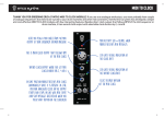
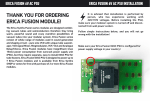
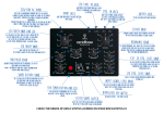
ERICA SYNTHS MIDI TO CLOCK BUILD MANUAL
THANK YOU FOR ORDERING
ERICA SYNTHS MIDI TO CLOCK
MODULE KIT!
If you are true analogue enthusiast, you most probably have couple of
analogue sequencers that need to be synced to your drum machines and
other midi controllers, therefore Erica synths has developed a simple,
easy to build and cost-effective MIDI TO CLOCK module with few interesting features. Besides direct clock output that follows BPM of the midi
sequencer or drum machine, it has second clock output with selectable
clock division by 2, 4 and 8. It has low part count and doesn’t need calibration, PCB comes with pre-soldered and pre-programmed microcontroller. Power supply circuit is diode protected, so you will not kill the
module in case you switch polarity of PSU cable.
TECHNICAL CHARACTERISTICS:
Panel width
Module depth
Power consumption
Output signal
6HP
20mm
10mA@+12V, 0mA@-12V
0-5V, 50% pulse
User manual by Girts Ozolins@Erica Synths. Design by Edgars Rasins.
Copying, distribution or any commercial use in any way is prohibited and
needs the written permission by Erica Synths. Specifications are subject to
change without notice. In case of any questions, feel free to contact us
through www.ericasynths.lv or via e-mail [email protected]. Check out
other Erica Synths DIY projects and assembled modules on
www.ericasynths.lv
Midi activity LED – blinks, when module
receives midi messages
Here you plug a midi cable from the midi output
of your sequencer or drum machine
LED gives visual indication of the clock rate
This is main clock output that follows BPM of
the midi clock
LED gives visual indication of the divided clock
rate
Divided clock output where you get midi clock
divided for 2, 4 or 8
In CONT position module receives midi clock
continuously until it is present. In CTRL
position analogue clock on the output starts
and stops in line with midi start and stop
messages received or when you push start
button on the sequencer
Select desired division of the midi clock
ERICA SYNTHS MIDI-CLOCK MODULE SCHEMATICS
(
#
$
#
(
%&'
)#
4/8377
(
/0123!45
#
&
((3(67
#
$
#
#
#
((
#
((
(
&
((#-
2/92:;;<69
#
(
'+!,
%*(!'
%*(!
((#-
!)(
((&!)
(!)
(!)
(
(
!)(
#!
!!
#
!
#
&
(('((.
! ((!*
! (!(*
! (!*
*(*
(*
!)(* '##-*
'#-*
(*%&& *
'&#*(*
!
#!
!(
* '
!* '
!!
'
#!
"
BILL OF MATERIALS
BEAD
PRESOLDERED
ON THE PCB
PRESOLDERED
ON THE PCB
CONSTRUCTION
Follow instructions below, and you cannot go wrong with
construction! From the first sight you may miss the pre-soldered microcontroller, but it’s really there and it’s really
micro.
Solder all resistors, diodes, transistors, IC socket, ferrite bead
and PSU jack.
CONSTRUCTION
Use screws supplied to fix the midi jack to the front panel.
Turn the PCB around. Insert jacks and switches in relevant
places on the PCB (do not solder them yet) and put the panel
on. If you are happy with their positioning, solder those to
the PCB. Insert LEDs in relevant places on the PCB (do not
solder them yet) and put the panel on. Lead LEDs through
the relevant holes on the front panel, and when you are
happy with their positioning, solder LED legs.
CONSTRUCTION
Put the panel on and use jack and switch nuts to fix it.
Solder midi jack wires to the relevant places on the PCB
Insert the optoisolator IC.
CONGRATULATIONS, YOU HAVE COMPLETED
ERICA SYNTHS MIDI TO CLOCK MODULE!