1
CHLORIDE Trinergy
UPS Systems from 200 to 1200 kVA
3 System description
3.4 Power Modules
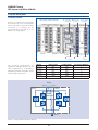
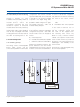
Each of the Trinergy power modules
has eight separate drawers which allow
for improved serviceability of the
individual power modules. The power
module contains:
•
•
•
•
•
Full IGBT rectifier,
IGBT Booster/battery charger
IGBT inverter
Power interface/Static Bypass
Power control
Each power module will be fitted with
the following switches:
•
•
•
•
Input
Output
Battery
Neutral
These switches will make it possible to
completely isolate a single power
module for maintenance or service
operation. As a result, there will be no
interruption to the power of the critical
load when it is necessary to take a
power module out of service for
maintenance or repair. Isolation will
be complete and all serviceable
components such as fuses, internal
power functional modules etc will be
isolated.
Remaining power modules will
continue to power the load making it
possible to perform maintenance
operation on the system while
maintaining the highest level of power
protection and avoiding the need to
switch the whole system to manual
maintenance bypass.
3.5 Microprocessor control and
diagnostics
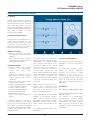
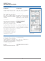
Operation and control of the UPS will
be provided through the use of microprocessor-controlled logic. Indications,
measurements and alarms, together
with battery autonomy, will be shown
on a graphic LCD touch screen display.
The procedures for start up, shutdown
and manual transfer of the load to and
from bypass will be explained in clear
step-by-step sequences on the LCD
display.
Several algorithms included in the
vector control firmware are covered by
patents owned by Chloride (95 P3875,
95 P3879 and 96 P3198).
3.6 Control and diagnostics
The precise control of Trinergy allows
it to quickly and seamlessly activate
one of the three different functioning
modes of the UPS in order to
accomplish
the
efficiency
and
effectiveness of each of the standard
configurations. At the same time,
Trinergy continues to maintain the
performance and power protection of a
Class 1 (IEC 62040-3) UPS for the load
and perfect input power conditioning
for the upstream distribution.
Control of the electronic power
modules will be optimised in order to
provide:
• Optimum three-phase supply and
conditioning of the load
• Controlled battery charging
• Minimum effects upon the supply
network
Trinergy houses an advanced digital
control platform that combines the
advantages of a double DSP which
executes all the vector control
algorithms and the Microcontroller
which gives maximum communication
flexibility whilst interfacing all internal
and external signals. Thanks to this
platform
Trinergy
will
achieve
the most powerful control in the
UPS industry.
3.6.1 Vector control & Trinergy
algorithm
To ensure the quick and flexible
processing of measuring data, special
arithmetic
algorithms
will
be
implemented in DSP, rapidly generating
controlled variables as a result. This will
thus render possible the real-time
control of the inverter electronics,
resulting in obvious advantages in the
performance
of
the
power
components. These advantages will be:
• Improvement of short circuit
behaviour, as individual phases can
be controlled faster
• Synchronism or phase angle
precision between UPS output and
bypass supply even in the case of a
distorted mains voltage
• High flexibility in parallel operation:
parallel Trinergy systems may be
housed in separate rooms.
05
3.6.2 Preventive monitoring
In order to maximise the reliability of
the system, the control unit will
monitor a wide number of operating
parameters for the rectifier, inverter
and battery. All vital operating
parameters, such as temperatures,
frequency and voltage stability at the
system input and output, load
parameters and internal system values
will be constantly monitored and
controlled for irregularities. The system
will react automatically before a critical
situation arises either for the UPS or
the load, in order to ensure the supply
of the load even in these difficult
conditions.
3.6.3 Telediagnosis and telemonitoring
In all the above modes of operation,
the UPS may be monitored and
controlled from a remote location such
as a service centre, in order to maintain
system reliability at nominal levels.
Even during complete shutdown of the
UPS, information relating to the
operating parameters will not be lost
thanks to non volatile FRAM which will
store the information for up to 45
years.
MKA4CAT0UKTRIN/Rev 1-09/2009/UK